Table of Contents
Advertisement
Quick Links
Advertisement
Table of Contents

Related Manuals for Rhosonics SDM


Summary of Contents for Rhosonics SDM
- Page 1 meter...
- Page 2 While efforts were made to verify the accuracy of the information contained in this document, faults in general are, however, never ruled out. If in doubt of the written information directly contact Rhosonics. Rhosonics will publish updates and revisions of this document as needed. The document supersedes all previous ones.
-
Page 3: Table Of Contents
SDM – Slurry Density Meter CONTENT PREFACE ........................ 6 URPOSE OF THIS MANUAL ........................... 6 ARGET AUDIENCE ........................... 7 PERATORS ..........................7 EADING GUIDE ..........................8 BBREVIATIONS ..........................9 DENTIFICATION INTRODUCTION ..........................10 NTENDED USE ........................10 INTENDED USE .............................11 IFESPAN ........................12 RODUCT SPECIFICATIONS 2.4.1... - Page 4 SDM – Slurry Density Meter 5.6.2 ....................33 ONNECTING THE PROTECTIVE EARTH 5.6.3 ......................34 ONNECTING THE POWER CABLE 5.6.4 HART ....................36 ONNECTING THE DATA CABLE 5.6.5 PT100 .........................39 ONNECTING THE OPERATION .......................43 NTRODUCTION AND USER LEVELS ......................44 DISPLAY AND BUTTONS 6.2.1 .....................44...
- Page 5 SDM – Slurry Density Meter 7.2.1 ......................65 SET CALIBRATION BASICS 7.2.2 .....................65 FACTOR CALIBRATION BASICS 7.2.3 .......................66 ORRECT DENSITY VALUES BASICS SDM SG ........................66 ALIBRATION SDM WT% ........................69 ALIBRATION MAINTENANCE ......................71 ENERAL MAINTENANCE TASKS ......................72 ETAILED MAINTENANCE TASKS 8.2.1 ...........................72 CLAMP 8.2.2...
-
Page 6: Preface
SDM – Slurry Density Meter PREFACE This user manual covers the following: the Slurry Density Meter, or 'SDM' for short. Please read this manual carefully for important information and instructions before using the Slurry Density Meter. Save this manual for future reference. -
Page 7: Operators
Trained personnel under the direct supervision of a qualified engineer. Personnel that have not yet been fully educated or instructed in the use of the SDM, may only work with the SDM when under permanent supervision of a qualified and trained engineer (or a person authorized by Rhosonics). -
Page 8: Abbreviations
SDM – Slurry Density Meter CAUTION NDICATES A POTENTIALLY HAZARDOUS SITUATION THAT IF NOT AVOIDED MAY RESULT IN MINOR TO MODERATE INJURY AND OR PRODUCT OR PROPERTY DAMAGE AND OR LOSS OF INFORMATION NOTE HIS SHOWS EXTRA INFORMATION THAT MAY HELP THE USER Other reading instructions: •... -
Page 9: Identification
SDM – Slurry Density Meter Identification The identification plate contains information about the SDM. When contacting Rhosonics, please state the information supplied on the identification plate. The identification plate is mounted on the side or on the bottom of the SDM, see Figure 1-1, pos. 1. -
Page 10: Introduction
SDM – Slurry Density Meter INTRODUCTION In this introduction, you can find general information on: • Intended and non-intended use of the slurry density meter (SDM); • Lifespan of the product; • Product specifications of the product. Intended use This product can only be used for measuring the density of slurry that flows through pipe systems. -
Page 11: Lifespan
WITHOUT CONSULTATION AND WRITTEN PERMISSION FROM HOSONICS ODIFICATIONS WITHOUT CONSULTATION CAN LEAD TO LIFE THREATENING SITUATIONS Spare parts must always meet the technical specifications as laid down in the SDM spare parts list. If in doubt, consult Rhosonics. www.rhosonics.com SDM Manual... -
Page 12: Product Specifications
SDM – Slurry Density Meter Product specifications The product specifications of the SDM can be found below. 2.4.1 Operation characteristics - Density PROPERTY WT (in %) Resolution 0.2 SGx1000 0.02 % Accuracy Up to +/- 0.5% of reading Up to +/- 0.5% of reading Reproducibility 0.2 SGx1000... -
Page 13: Sdm Housing
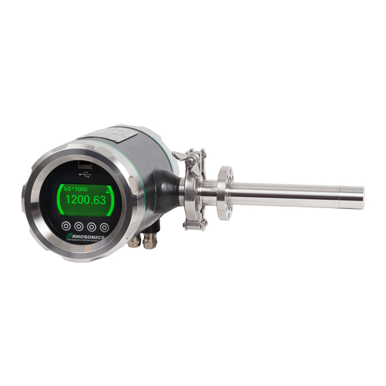
SDM – Slurry Density Meter 2.4.4 SDM housing Figure 2-1: SDM housing dimensions PROPERTY VALUE Dimensions SDM housing Ø125x212 mm (ØxL) Display, effective area 65x35 mm (WxH) IP rating with covers IP 68 IP rating without covers IP 54 Ambient Temperature -5°C to +50°C... -
Page 14: Sdm Sensor - Wetted Parts
SDM – Slurry Density Meter 2.4.5 SDM sensor – wetted parts PROPERTY COMPOSITION / NORM (Alloyed) Silicon nitride Si3N4 Duplex Steel ASTM/ASME: A240 UNS S32205/S31803 EURONORM: 1.4462 X2CrNiMoN 22.5.3 AFNOR: Z3 CrNi 22.05 AZ DIN: W.Nr 1.4462 ISO: 4462-318-03-I BS: 318S13... -
Page 15: General Description
SDM – Slurry Density Meter GENERAL DESCRIPTION The slurry density meter (SDM) is a product that is used to measure the density of slurry that flows through pipe systems. Its main components are: • a transmitter; • a sensor for measuring slurry. - Page 16 SDM – Slurry Density Meter Figure 3-2: O-rings Legend O-ring for sensor contact O-ring for sensor flange www.rhosonics.com SDM Manual (V2.1)
-
Page 17: Components Functionality
The tri clamp (Figure 3-3, pos. 7) is pre-assembled and connects the sensor (Figure 3-3, pos. 2) to the transmitter (Figure 3-3, pos. 1). The sensor (Figure 3-3, pos. 2) has a mounting flange (Figure 3-3, pos. 5) for mounting the SDM onto a pipe integration system (not shown). -
Page 18: Pipe Integration Systems
SDM – Slurry Density Meter Pipe integration systems To use the SDM, it needs to be integrated within a pipe system. Several pipe integration systems are available. To get information on the best suited pipe integration system, contact Rhosonics. NOTE... -
Page 19: Safety
If you suspect the SDM has previously been misused, arrange for an inspection by a qualified expert. Local safety rules Users of the SDM should make sure they are in compliance with all other relevant safety rules in force at the site of operation. These include: •... -
Page 20: Warning Symbols On/Near The System
Always comply with safety instructions and hazard warnings. Always ensure that safety instructions and hazard warnings are well looked after and legible. When working with the SDM, a number of warning and prohibition symbols might present themselves on pipes and/or equipment surrounding or near the SDM. -
Page 21: Temperature Ranges
HEN WORKING IN LOW TEMPERATURES PREVENT HYPOTHERMIA AND INJURIES FROM FROSTBITE BY WEARING SUITABLE CLOTHES SHOES GLOVES AND HEAD PROTECTION The SDM can operate safely with the following temperature ranges: PROPERTY TEMPERATURE RANGE IN °C TEMPERATURE RANGE IN °F Environmental temperature when in use -5 °C to +50 °C... -
Page 22: Preparations Working Area
SDM – Slurry Density Meter Preparations working area WARNING EEP THE WORKSPACE AS CLEAN AND SAFE AS POSSIBLE TO PREVENT ACCIDENTS AND DANGEROUS SITUATIONS To prevent accidents and dangerous situations, it is very important that the working area is very well looked after: •... -
Page 23: Installation
SDM – Slurry Density Meter INSTALLATION Supplies and items for installation CAUTION F ANY OF THE BASIC SUPPLIES DELIVERED BY HOSONICS ARE DAMAGED OR COMPROMISED CONTACT HOSONICS FOR REPLACEMENTS OR FURTHER INSTRUCTIONS EVER USE DAMAGED SUPPLIES NOTE F AN OLDER INSTALLATION OF A... - Page 24 SDM – Slurry Density Meter Figure 5-1: SDM packaging contents The contents of the chosen pipe integration system are mentioned in its accompanying manual. NOTE EPENDING ON THE AGREED UPON PIPE INTEGRATION SYSTEM HOSONICS MIGHT ADD COMPONENTS OF SDM- THAT PIPE INTEGRATION SYSTEM TO THE ORIGINAL...
-
Page 25: Guidelines For Vertical Pipe Mountings
A straight pipe downstream with an uninterrupted length of at least 3 times the diameter of the pipe; • SDM must be placed in a verticale pipe at an straight (90°) angle in relation to the connected horizontal pipe (Figure 5-2). Vertical pipe mounting only results in reliable measurements if the flow goes in upstream direction. -
Page 26: Guidelines For Horizontal Pipe Mountings
CAUTION LWAYS POINT THE CABLE GLANDS DOWNWARDS TO PREVENT INTRUDING LIQUIDS Make sure you mount the SDM with the display in the correct position and the cable glands pointing downwards to prevent intruding liquids. Figure 5-3: Horizontal pipe mounting example www.rhosonics.com... -
Page 27: Mounting The Pipe Integration System
SDM – Slurry Density Meter Mounting the pipe integration system CAUTION EALING METAL FLANGES REQUIRES SKILLS KNOWLEDGE AND EXPERIENCE PECIAL REQUIREMENTS MAY APPLY DEPENDING ON THE PIPE SYSTEM IN WHICH THE PIPE INTEGRATION SYSTEM IS INSTALLED YOU ARE NOT FAMILIAR WITH THE NECESSARY PROCEDURES... - Page 28 SDM – Slurry Density Meter PIPE INTEGRATION SYSTEM SUITABLE PIPE TYPE Do it yourself (DIY) adapter - Pipes with a liner Figure 5-6: DIY Adapter UWC wafer - Pipes 4” - 60” - UHPE - 316 - 304 - 904...
-
Page 29: Installation Of The Sdm
Make sure that all eight (8) threaded holes of the receiving flange are clean and undamaged. Figure 5-9: Receiving flange of pipe integration system 3. Make sure that the SDM and its installation materials are complete, clean and undamaged. www.rhosonics.com SDM Manual (V2.1) -
Page 30: Installing The Sdm
• O-ring: Viton, 29.82x2.62 mm, 1 piece. 1. Ensure that no power is applied to the transmitter when installing the SDM. 2. Place the washers onto the bolts and keep them within reach. 3. Remove the black protective cap (Figure 5-10, pos. 1) from the sensor. - Page 31 Figure 5-11: O-ring placement 5. Gently slide (as straight as possible) the SDM into the pipe integration system and align the screw holes of both flanges (Figure 5-12). Choose the position in such a way that the display is easy to be read.
- Page 32 6. Safely hold the SDM in place while mounting the screws in the next step. 7. Place the eight bolts (with their washers) through the holes of the SDM’s flange, into the threaded holes of the receiving flange (Figure 5-13).
-
Page 33: Connecting The Sdm
SDM – Slurry Density Meter Connecting the SDM Before connecting the SDM, make sure all supplies match the requirements from the tables in chapter 5.6.1. 5.6.1 Supply requirements • Power supply requirements ITEM VALUE Input voltage 18 - 30 V DC... -
Page 34: Connecting The Power Cable
SDM – Slurry Density Meter 5.6.3 Connecting the power cable DANGER LWAYS MAKE SURE THAT POWER CABLES ARE NOT CONNECTED TO A POWER SUPPLY WHILE CREATING NEW CONNECTIONS CONNECT THE POWER SUPPLY AFTER CONNECTIONS HAVE BEEN SAFELY MADE AND THE CABLE COMPARTMENTS ARE SAFELY CLOSED AND SEALED CAUTION SDM. - Page 35 3. Connect the power cable to the power connection (Figure 5-17, pos. 1) using the screw connectors. Figure 5-17: Power connection 4. Tighten the cable gland (Figure 5-18, pos. 1) to prevent moisture and dirt entering the SDM. Figure 5-18: Cable gland 5.
-
Page 36: Connecting The Hart Data Cable
SDM – Slurry Density Meter 5.6.4 Connecting the HART data cable DANGER LWAYS MAKE SURE THAT POWER CABLES ARE NOT CONNECTED TO A POWER SUPPLY WHILE CREATING NEW CONNECTIONS NLY RECONNECT THE POWER SUPPLY AFTER CONNECTIONS HAVE BEEN SAFELY MADE AND THE CABLE COMPARTMENTS ARE SAFELY CLOSED AND SEALED CAUTION SDM. - Page 37 Figure 5-21: HART connection 6. Tighten the newly placed cable gland to prevent moisture and dirt entering the SDM. 7. Connect a PT100 cable if necessary, using a spare cable gland for the cable entry (Figure 5-22, pos. 1 ).
- Page 38 SDM – Slurry Density Meter Figure 5-22: PT100 cable entry 8. Close the back lid. Figure 5-23: Back lid www.rhosonics.com SDM Manual (V2.1)
-
Page 39: Connecting The Pt100
CABLE IS OPTIONAL AND ONLY NECESSARY IN EXTREME TEMPERATURE CONDITIONS The PT100 connection is used for temperature measurements. It consists of a block-form connector that can be connected to the PT100 connector on the back plate of the SDM. Figure 5-24: PT100 connector www.rhosonics.com... - Page 40 SDM – Slurry Density Meter 1. Open the back lid. 2. Remove the blind plug (Figure 5-25, pos. 1) at the centre cable entry. 3. Install a spare cable gland into the cable entry. 4. Guide the PT100 cable through the cable gland.
- Page 41 Figure 5-27: PT100 connector 8. Tighten the 2 screws on the far left and far right of the block-form connector. 9. Tighten the cable gland (Figure 5-28, pos. 1) to prevent moisture and dirt entering the SDM. Figure 5-28: Cable gland 10.
- Page 42 SDM – Slurry Density Meter Figure 5-29: Back lid 11. Erase the log from the SDM, see chapter 6.3.11, and wait for 60 seconds. 12. The temperature measurement can be enabled and disabled: Main Menu -> Advanced functions -> PT100 connected.
-
Page 43: Operation
SDM – Slurry Density Meter OPERATION Introduction and user levels The SDM is operated via the buttons and display for day-to-day use. Local supervisors, service engineers or distributors have access to more advanced options for operation via HART and/or the USB-port. -
Page 44: Sdm Display And Buttons
SDM display and buttons 6.2.1 Accessibility and functionality The SDM display and its buttons support several access level functionalities. Setting time and date, setting the log interval and a minor system status icon displays the most relevant error in case of measurement problems. -
Page 45: Symbols, Buttons And Icons
SDM – Slurry Density Meter 6.2.2 Symbols, buttons and icons During operation, several items can be visible on the display (Figure 6-2). ITEM / ICON EXPLANATION LOCATION ON SCREEN Current access level Top right corner Unlocked (local access) Top right corner... -
Page 46: Status Sdm And Display Colors
6.2.3 Status SDM and display colors The status of the SDM is shown through different icons and backlight colors. Unless the black and white backlight mode is enabled, see chapter 6.3.5. The screen has two modes: active and time-out. The active mode is activated by pressing a button. If a button isn’t pressed for 10 minutes the screen will return to the time-out mode. - Page 47 Unlocked (local access) Status: Normal operation Output: Valid Info: Device is operating within specified range. Info: In time Out Access level will be reset to level 1. Table 6-2: SDM states and modes - Green colored www.rhosonics.com SDM Manual (V2.1)
- Page 48 Device is in maintenance Output: Valid Output: Valid / Icon and measurement values are alternating. Device is in maintenance. Info: Device is in maintenance. Info: Table 6-3: SDM states and modes – Yellow, blue and orange colored www.rhosonics.com SDM Manual (V2.1)
- Page 49 Unlocked (local access) Accessibility: Unlocked (local access) Status: Failure Status: Failure Output: Invalid Output: Invalid / Icon and measurement values are alternating. Replace device. Info: Replace device. Info: Table 6-4: SDM states and modes – Red colored www.rhosonics.com SDM Manual (V2.1)
-
Page 50: Operation Via Sdm Display And Buttons
Home page The first page seen when the SDM is starting up is the Software Page, see Figure 6-5 on page 63. When a key is pressed in time-out mode, the Home Page will be shown. The Home Page contains four values: the HART communication values. -
Page 51: Measured Values
Once the Black and white mode is enabled, the SDM will no longer display its status in a colored display. Select NAMUR color to reset the color display. -
Page 52: Display Lines
Display lines Main Menu -> Display lines. On the SDM you can choose how much information is shown while in time-out mode. The time-out mode is activated after 10 minutes if no actions are performed on the SDM. The default setting is zero (0) display lines and there are 3 options: •... -
Page 53: Access Code
SDM – Slurry Density Meter 6.3.7 Access code Main Menu -> Advanced Function. A higher Access Code is required to access the Advanced Function menu and all related functions. Access code for level 2 is 1802. Entering the Advanced Function menu, the Access Code page will appear if you are not already in level 2. -
Page 54: Diagnostics Menu
SDM – Slurry Density Meter 6.3.9 Diagnostics menu Main Menu -> Advanced Function -> Diagnostics Menu. In the Diagnostics Menu you can choose from 6 options: • Logging Menu • Erase log • System status • Set Clock • Restore Calibration •... -
Page 55: Erase Log
6.3.13. Press the button to erase the log. 6.3.12 System status Main Menu -> Advanced Function -> Diagnostics Menu -> System Status. On this page you will find information on the SDM. • Software version • Status If the status is OK, Normal Operation is shown. -
Page 56: Set Clock And Date
SDM – Slurry Density Meter 6.3.13 Set clock and date CAUTION F THE TIME OR DATE IS SET MAKE SURE TO ERASE THE LOG AFTERWARDS O ERASE THE LOG CONSULT 6.3.13. CHAPTER Main Menu -> Advanced Function -> Diagnostics Menu -> Set Clock. -
Page 57: Restore Calibration
Main Menu -> Advanced Function -> Calibration Menu. In the Calibration Menu you can choose from 3 options: • Temperature • SGx 1000 • FIELD (for SDM WT% only) For instructions on the calibration of the SDM, see chapter 7 on page 64. www.rhosonics.com SDM Manual (V2.1) -
Page 58: Liquid Menu
Main Menu -> Advanced Function -> Write Protect. Write protect mode is used when the HART communication for the SDM is used. If the HART communication is not used, this menu is not used and write protect mode should be set to Off. -
Page 59: Output M Arange
SDM – Slurry Density Meter The Check Function can be used for 2 things: • When HART is used the DCS is warned that the SDM is in maintenance. The values sent to the DCS may be invalid. • Another function is that a COM-port is configured for a service PC to be used by a Rhosonics service engineer. -
Page 60: Operation Via Usb
Power off the SDM by interrupting the power supply. Insert an USB-stick with the latest software and the file bootscript.img. Power on the SDM by restoring the power supply. Wait until the SDM has booted and the software version is shown in the screen. Disconnect the USB-stick. NOTE... -
Page 61: Saving Settings And Log Data Via Usb
Saving settings and log can be done for diagnostics evaluation and for troubleshooting. When a log-file is stored to the USB stick the settings from the SDM will be stored as well. The settings from the SDM can then be interpreted by the factory. -
Page 62: Connecting The Sdm Via The Usb To A Laptop Or Pc
EE CHAPTER ROUBLESHOOTING 6.5.3 Connecting the SDM via the USB to a laptop or PC For instructions on connecting the SDM via the USB-port to a laptop or PC, contact Rhosonics at service@rhosonics.com. 6.5.4 Load sensor settings Before uploading the sensor file, you need to make sure: •... -
Page 63: Rebooting The Sdm
To reboot the SDM: 1. Press the two outer buttons (Figure 6-4, pos. 1 and pos. 2) simultaneously for two seconds. 2. The display will show a message that the SDM will be rebooted within 30 seconds. Figure 6-4: SDM reboot... -
Page 64: Calibration
SDM – Slurry Density Meter CALIBRATION CAUTION SDM-SG SDM-SG MUST BE CALIBRATED FOLLOWING THE CALIBRATION METHOD SDM-WT% SDM-WT% MUST BE CALIBRATED FOLLOWING THE CALIBRATION METHOD IXING UP CALIBRATION METHODS WILL RESULTS IN INCORRECT READINGS NOTE EFORE YOU START CALIBRATING MAKE SURE THAT THE... -
Page 65: Calibration Basics
SDM – Slurry Density Meter Calibration basics To calibrate the SDM, take notice of the calibration basics in chapter 7.2.1, chapter 7.2.2 and chapter 7.2.3 to make sure measurement values are reliable. 7.2.1 Off-set calibration basics After installation, we need to check if the density value of clear liquid is right. In customer processes the density may deviate from the real value due to slightly different circumstances in the process pipe. -
Page 66: Correct Density Values Basics
Main Menu -> Advanced Function -> Diagnostics Menu -> Restore Calibrations. 4. Clear the log from the SDM, see chapter 6.3.11. Wait for 60 seconds. Reboot the SDM, see chapter 6.6. Or disconnect and reconnect the power supply. (Only necessary if step 3 has been performed) Main Menu ->... - Page 67 SDM – Slurry Density Meter 6. Pump water for 30 minutes to monitor the SDM and verify that you have a stable SGx1000 reading. 7. Check the temperature of the water. Adjust the temperature to the correct value if needed.
- Page 68 Figure 7-5: Calibration span factor formula SGCertified is the value of the sample. SGUncorrected is the value read on the SDM at the time of sampling (on screen or in log file). SGoffset is the number 1000 (represents water). Example: SGCertified is 1600SG-1000SG. SGUncorrected is 1205SG-1000SG makes 600:205 and gives a span factor of 2.92.
-
Page 69: Calibration Sdm Wt
Main Menu -> Advanced Function -> Diagnostics Menu -> Restore Calibrations. 4. Clear the log from the SDM, see chapter 6.3.11. Wait for 60 seconds. Reboot the SDM, see chapter 6.5.3. Or disconnect the power for a short time. (Only necessary if step 3 has been performed) Main Menu ->... - Page 70 SDM – Slurry Density Meter 9. Pump slurry for 30 minutes to monitor the SDM and verify that you have a stable SGx1000 reading. 10. Check the temperature of the slurry and calibrate this with an offset calibration. The temperature should be equal to the average process temperature when pumping slurry.
-
Page 71: Maintenance
SDM – Slurry Density Meter MAINTENANCE General maintenance tasks The SDM needs general maintenance every 3 – 6 months. Follow the general maintenance tasks below: 1. Check if the earth connection (Figure 8-1, pos. 1) is: • free from rust, dust, dirt and moisture;... -
Page 72: Detailed Maintenance Tasks
‘R ’. HOSONICS SAMPLING PROCEDURE 4. Check the SDM values. Take reference samples during a stable process / reading. Consult the manual ‘Rhosonics sampling procedure’. In case of a deviation, take the following actions: • Check the process temperature. Validate the set temperature of the SDM;... -
Page 73: Transmitter And Sensor Connections
SDM – Slurry Density Meter 8.2.2 Transmitter and sensor connections CAUTION E AWARE THAT THE TRANSMITTER AND SENSOR CONNECTIONS ARE FRAGILE CAUTION HEN DISCONNECTING THE CABLES NO TENSION WHATSOEVER IS ALLOWED ON THE CABLES TENSION ON ANY CABLE IS PRESENT... - Page 74 SDM – Slurry Density Meter 4. Loosen the nut (Figure 8-5, pos. 2) of the tri clamp (Figure 8-5, pos. 1). Figure 8-5: Tri-clamp nut loosening 5. Remove the transmitter and the tri clamp. 6. If needed, clean the: •...
- Page 75 • the contact pin will return due to the spring. Figure 8-7: Sensor contact pins 8. If the SDM remains disassembled; protect the sensor or/and transmitter: • place the yellow protection cap on the transmitter, see Figure 8-8, pos. 1;...
- Page 76 SDM – Slurry Density Meter Figure 8-9: Yellow protection cap on sensor 9. If the SDM needs to be re-assembled, make sure that the 2 O-rings are present in the transmitter and sensor, see Figure 8-10, pos. 1 and 2.
-
Page 77: Sensor
SDM – Slurry Density Meter 8.2.3 Sensor CAUTION HEN DISCONNECTING THE CABLES NO TENSION WHATSOEVER IS ALLOWED ON THE CABLES TENSION ON ANY CABLE IS PRESENT IMMEDIATELY DISCONNECT ALL CABLES TO PREVENT DAMAGE NOTE 8-11, . 2), EFORE REMOVING THE... - Page 78 SDM – Slurry Density Meter 2. Remove the 4–20 mA cable or the combined cable (Figure 8-12, pos. 1). Figure 8-12: 4–20 mA cable 3. Support the transmitter by hand. NOTE E AWARE THAT THE TRANSMITTER WEIGHTS APPROXIMATELY HE TRANSMITTER WILL DETACH FROM THE SENSOR WHEN THE TRI CLAMP IS LOOSENED 4.
- Page 79 SDM – Slurry Density Meter Figure 8-14: Sensor contacts 7. Remove the bolts and washers (Figure 8-15, pos. 1). Figure 8-15: M5 bolts and washers 8. Remove the sensor from the pipe integration system. WARNING E AWARE TO ONLY ROTATE THE SENSOR IN CLOCKWISE DIRECTION...
- Page 80 SDM – Slurry Density Meter Figure 8-16: Connection pins NOTE N DOUBT OF THE CONDITION TAKE PICTURES AND CONTACT HOSONICS 10. Place back the sensor in the exact same position (Figure 8-17, pos. 3). Figure 8-17: Sensor position markings NOTE...
- Page 81 SDM – Slurry Density Meter 11. Clean and inspect the grooves for the 2 O-rings (Figure 8-18, pos. 1 and 2). 12. If needed, apply high vacuum grease to the grooves. 13. Make sure that the 2 O-rings are present at the transmitter and sensor (Figure 8-18, pos. 1 and 2).
-
Page 82: Sensor Settings
• that the 3ASENSOR.CSV file has the same software version as the SDM transmitter: check the current software version of the SDM transmitter, see chapter 6.7. For rebooting see chapter 6.6. Check the software version of the file. Open the 3Asensor.CSV file from the supplied USB stick in excel. -
Page 83: Troubleshooting
TROUBLESHOOTING The SDM is designed to work maintenance free for a long time. Of course, as in every technical unit, an issue may occur. Here are some tips on how to find a solution. If this does not solve your problem or if your problem is not listed, contact Rhosonics. -
Page 84: Issues And Solution
SDM – Slurry Density Meter Issues and solution The most common SDM issues and their problems are listed below: Issue Possible cause Possible solution Display is black / off. No power. Check power supply, see chapter 5.6.3. Check polarization of the power cable. - Page 85 SDM shows an orange screen SDM is in check function mode. Check the function, see with wrench. chapter 6.3.20. SDM shows a shield in the top SDM is in wright protect. Put off the write protect, see left corner. chapter 6.3.19.
- Page 86 SDM Is in check function mode Turn off check function mode, logging see chapter 6.3.20. SDM shows more than 1 value in Display lines is set to 1 or 2 Adjust the display lines 6.3.6. screen saver mode (Display line default is 0 extra...
- Page 87 SDM – Slurry Density Meter Issue Possible cause Possible solution SDM is always out of range. Air in the process. Gather information and contact Rhosonics, see chapter 9.1. SDM is measuring water while Water in front of the sensor. Gather information and contact pumping slurry.
-
Page 88: Resistance Check
SDM – Slurry Density Meter 9.2.1 Resistance check To measure the resistance of the transmitter and sensor: 1. Disconnect the power supply. 2. Remove the 4 to 20 mA cable. 3. Remove the Tri-clamp. 4. Check if the connection points are clean and free of moisture. - Page 89 SDM – Slurry Density Meter 5. Measure the resistance of the transmitter connection points. The resistance is around 55 to 57 ohms. Measure between the inner and outer connection point (Figure 9-1, pos. 1 and 2). Figure 9-1: Transmitter connection 6.
- Page 90 7. Measure the resistance of the sensor. The resistance must be lower than 50 ohms. Measure between the outer connection point and the end of the sensor (Figure 9-3, pos. 1 and 2). Figure 9-3: O-rings 8. Contact Rhosonics if the resistance is not correct. www.rhosonics.com SDM Manual...
-
Page 91: Problem With Transfer
4. Select the option ‘erase the log’ from the SDM (chapter 6.3.11). 5. Reboot after 1 minute. After the memory of the SDM has been cleared, the problem is solved. All the history of the SDM is deleted. To prevent the transfer error: 1. -
Page 92: Red Screen
SDM – Slurry Density Meter 9.2.3 Red screen NOTE 6.2.3. OR MORE INFORMATION ABOUT THE RED SCREEN SEE CHAPTER A red screen indicates a problem with the transmitter or the sensor, see Figure 9-5. Figure 9-5: Red screen To solve the red screen: 1. -
Page 93: Yellow Screen
2. Check the 4-20 mA setting. 3. To set the 4-20 mA setting, see chapter 6.3.21. If the issue is not solved, contact Rhosonics. Example: 1. 4-20 mA has been set to 4 mA = 1000 and 20 mA = 2000 2. -
Page 94: Orange Screen
SDM – Slurry Density Meter 9.2.5 Orange screen NOTE 6.2.3. OR MORE INFORMATION ABOUT THE ORANGE SCREEN SEE CHAPTER An orange screen indicates the check function mode is enabled, see Figure 9-7. Figure 9-7: Orange screen To solve the orange screen: 1. -
Page 95: Frequently Asked Questions
Answer Where or how can I find the SDM software See chapter 6.7. version? Where can I find the serial number of the SDM? The serial number can be found: • on the outside of the SDM (sticker, see chapter 1.6);... - Page 96 • air or; • very high density. SDM is outside the set 4 to 20 mA, see chapter 6.3.21. What does error code 79 ‘failure in system’ in There is a problem with the transmitter or the system status menu mean? sensor, see chapter 8 or 9.2.3.
-
Page 97: Transport And Storage
Transport When transporting the SDM, the SDM must be safely packed into a strong box – preferably in its original box - that protects it from outside moisture and dust. Make sure to add material inside the box and around the SDM that protects it from damage in case the box bumps or drops. -
Page 98: Appendices
SDM – Slurry Density Meter APPENDICES 13.1 List of spare parts DESCRIPTION PART NUMBER CONSISTS OF SDM Sensor only (no transmitter SDM Sensor SDM Sensor included) - spare part SDM transmitter SDM transmitter SDM transmitter Back cover Back cover Back cover... -
Page 99: List Of Options
Blind Plug (for the installation BP-60T13-HDPE-UNIVERSAL- HDPE blind plug 16-146 mm with 1 x O-ring tool) VITON Viton® 51414 Ø20,3x2,62 and 1 x O-ring 29.82x2.62 Viton 80S Table 13-2: List of options Figure 13-1: SDM Sun shade roof www.rhosonics.com SDM Manual (V2.1) -
Page 100: Menu Tree
SDM – Slurry Density Meter 13.3 Menu tree → Measured values → Decay time → 0-99 sec → Back-light → Namur color → Black and white → Display → 0 to 2 lines → Advanced → Diagnostics → Logging menu → Log interval →... -
Page 101: Functionality Per User Interface
SDM – Slurry Density Meter 13.4 Functionality per user interface Each user interface has a different set of functions. They are categorized based on access level and accessibility of each type of user interface. This functionality is available per type of user interface:... -
Page 102: Appendix A: Sound Speed Of Water At To 100 °C
SDM – Slurry Density Meter 13.5 Appendix A: Sound speed of water at 0 to 100 °C T [°C] c [m/s] T [°C] c [m/s] T [°C] c [m/s] T [°C] c [m/s] 1402.388 1496.687 1542.551 1555.133 1407.367 1499.323 1543.619 1555.081... -
Page 103: Appendix B: Density Of Water At To 100 °C
SDM – Slurry Density Meter 13.6 Appendix B: Density of water at 0 to 100 °C T [°C] RHO [g/l] T [°C] RHO [g/l] T [°C] RHO [g/l] T [°C] RHO [g/l] 999.86341 997.04784 988.00825 974.85658 999.91390 996.78615 987.55238 974.25961 999.94857...
Need help?
Do you have a question about the SDM and is the answer not in the manual?
Questions and answers