Table of Contents
Advertisement
Quick Links
Advertisement
Table of Contents

Related Manuals for NI PXIe-7903


Summary of Contents for NI PXIe-7903
- Page 1 PXIe-7903 Getting Started 2024-04-08...
-
Page 2: Table Of Contents
Troubleshooting............. . 27 What Should I Do if the PXIe-7903 Does Not Appear in MAX?..... 27... -
Page 3: Pxie-7903 Getting Started
PXIe-7903 Getting Started Note Before you begin, install and configure your chassis and controller. This document explains how to install, configure, and troubleshoot the PXIe-7903 high-speed serial module. You can program the PXIe-7903 using NI-FlexRIO driver software For device specifications, refer to the PXIe-7903 Specifications. -
Page 4: Flexrio Documentation And Resources
PXIe-7903 Getting Started FlexRIO Documentation and Resources Use the following resources to find more information about the PXIe-7903. or in LabVIEW by clicking Help. All documentation can be found at ni.com/manuals Table 1. FlexRIO Documentation and Resources Document Contents PXIe-7903 Getting Started Guide (this Installation instructions ■... - Page 5 PXIe-7903 Getting Started Document Contents LabVIEW Examples Examples showing how to run FPGA VIs ■ on your device Examples showing how to run host VIs ■ on your device © National Instruments...
-
Page 6: Unpacking The Kit
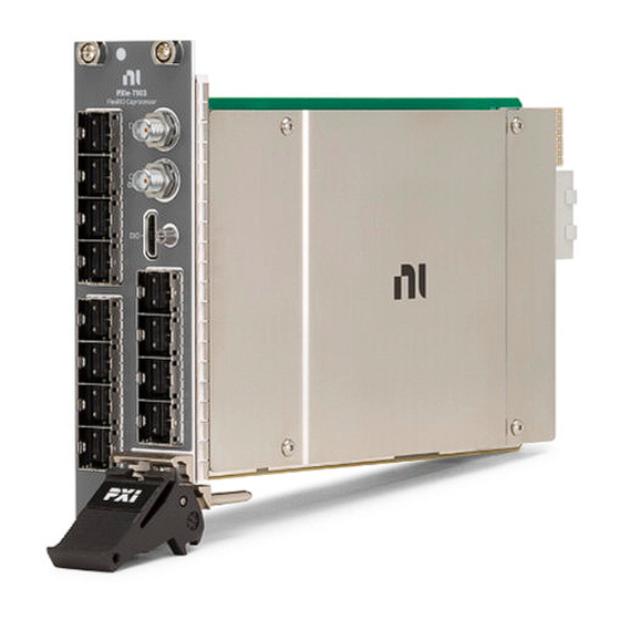
3. Unpack any other items and documentation from the kit. Store the device in the antistatic package when the device is not in use. What You Need to Get Started Kit Contents Verify that the following items are included in the PXIe-7903 kit. ni.com... - Page 7 PXIe-7903 Getting Started Figure 1. PXIe-7903 PXIe-7903 Safety, Environmental, and Regulatory Information Recommended Cables NI recommends the following cables for use with the PXIe-7903. Model Description NI Part Number Mini-SAS zHD-Mini-SAS zHD 0.5 m zHD to zHD cable 788927-0R5 HSS Passive Cable...
- Page 8 Use care when handling zHD cables. If you meet resistance when connecting the cable, stop and inspect the cable; replace the cable if the EMI gasket is damaged. NI Mini-HDMI (Type C) cable used to connect the module to DIO ports on other devices. ni.com...
-
Page 9: Preparing The Environment
PXIe-7903 Getting Started Preparing the Environment Ensure that the environment you are using the PXIe-7903 in meets the following specifications. Caution Do not use the PXIe-7903 in a manner not specified in this document. Product misuse can result in a hazard. You can compromise the safety protection built into the product if the product is damaged in any way. -
Page 10: Installing The Software
PXIe-7903 Getting Started Installing the Software You must install the FlexRIO driver software before installing the PXIe-7903. 1. Install LabVIEW. Refer to the LabVIEW Installation Guide for installation instructions and system requirements. Refer to the LabVIEW Upgrade Notes for additional information about upgrading to the most recent version of LabVIEW. -
Page 11: Installing The Pxie-7903
2. Ensure that the chassis is powered off. 3. Install the PXIe-7903 into a chassis slot by first placing the module card PCB into the front of the card guides (top and bottom), as shown in the following figure. - Page 12 PXIe-7903 Getting Started Figure 2. Installing the PXI-7903 Module a. Injector/Ejector Handle b. FlexRIO Module c. Front Panel Mounting Screws (4x) d. PXI Express Chassis e. Injector/Ejector Rail ni.com...
-
Page 13: Pxie-7903 Front Panel
PXIe-7903 Getting Started PXIe-7903 Front Panel The following table and figures show the available connections on the PXIe-7903. Table 2. Connector Types Signal Connector Type Description 0–7 MiniSAS zHD Use passive, copper cables only 8–11 MiniSAS zHD Use passive or powered optical... - Page 14 DIO 7 DIO 6 DIO 5 DIO 4 DIO 3 DIO 2 DIO 1 DIO 0 Table 3. NI Mini-HDMI (Type C) Pinout Pin Number Signal Type Signal Description Ground Ground reference for signals No connection Ground Ground reference for signals...
- Page 15 Ground reference for signals Notice The DIO port is not an HDMI interface. Do not connect the DIO port on the PXIe-7903 to the HDMI interface of another device. NI is not liable for any damage resulting from such signal connections. Notice Do not connect a commercial HDMI cable to the PXIe-7903.
-
Page 16: Verifying The Installation In Max
Verifying the Installation in MAX Use Measurement & Automation Explorer (MAX) to configure your NI hardware. MAX informs other programs about which NI hardware products are in the system and how they are configured. MAX is automatically installed with FlexRIO. -
Page 17: Accessing Flexrio With Integrated I/O Examples
1. In LabVIEW, click Help » Find Examples. 2. In the NI Example Finder window that opens, click Hardware Input and Output » FlexRIO » Integrated IO » Getting Started. 3. Double click Getting Started with FlexRIO Integrated IO.vi. -
Page 18: Block Diagram
PXIe-7903 Getting Started Block Diagram Figure 5. PXIe-7903 Block Diagram Power Flash Supplies 3.3V GPIO Gen3x8 PCIe DStarB, DStarC 3.3V Optical (Ports 8-11 only) PXI Triggers 3.3V MGTs Control and Status FPGA Clock Generation IC 1 PXI_CLK10 MGT Reference PXIe_SYNC100... - Page 19 PXIe-7903 Getting Started Connector Mini-SAS zHD CLIP Signal Name Common Physical Channel Physical Connector Lane Resource Resource MgtPortRx_p/n(6), GTYE4_CHANNEL_ MgtPortTx_p/n(6) X0Y6 MgtPortRx_p/n(7), GTYE4_CHANNEL_ MgtPortTx_p/n(7) X0Y7 Port 2 MgtPortRx_p/n(8), GTYE4_COMMON_ GTYE4_CHANNEL_ MgtPortTx_p/n(8) X0Y2 X0Y9 MgtPortRx_p/n(9), GTYE4_CHANNEL_ MgtPortTx_p/n(9) X0Y8 MgtPortRx_p/ GTYE4_CHANNEL_ n(10),...
- Page 20 PXIe-7903 Getting Started Connector Mini-SAS zHD CLIP Signal Name Common Physical Channel Physical Connector Lane Resource Resource MgtPortRx_p/ GTYE4_CHANNEL_ n(17), X1Y16 MgtPortTx_p/ n(17) MgtPortRx_p/ GTYE4_CHANNEL_ n(18), X1Y18 MgtPortTx_p/ n(18) MgtPortRx_p/ GTYE4_CHANNEL_ n(19), X1Y19 MgtPortTx_p/ n(19) Port 5 MgtPortRx_p/ GTYE4_COMMON_ GTYE4_CHANNEL_...
- Page 21 PXIe-7903 Getting Started Connector Mini-SAS zHD CLIP Signal Name Common Physical Channel Physical Connector Lane Resource Resource MgtPortRx_p/ GTYE4_CHANNEL_ n(26), X1Y26 MgtPortTx_p/ n(26) MgtPortRx_p/ GTYE4_CHANNEL_ n(27), X1Y27 MgtPortTx_p/ n(27) Port 7 MgtPortRx_p/ GTYE4_COMMON_ GTYE4_CHANNEL_ n(28), X1Y7 X1Y29 MgtPortTx_p/ n(28) MgtPortRx_p/...
- Page 22 PXIe-7903 Getting Started Connector Mini-SAS zHD CLIP Signal Name Common Physical Channel Physical Connector Lane Resource Resource MgtPortRx_p/ GTYE4_CHANNEL_ n(35), X0Y19 MgtPortTx_p/ n(35) Port 9 MgtPortRx_p/ GTYE4_COMMON_ GTYE4_CHANNEL_ n(36), X0Y5 X0Y21 MgtPortTx_p/ n(36) MgtPortRx_p/ GTYE4_CHANNEL_ n(37), X0Y20 MgtPortTx_p/ n(37) MgtPortRx_p/...
- Page 23 PXIe-7903 Getting Started Connector Mini-SAS zHD CLIP Signal Name Common Physical Channel Physical Connector Lane Resource Resource Port 11 MgtPortRx_p/ GTYE4_COMMON_ GTYE4_CHANNEL_ n(44), X0Y7 X0Y29 MgtPortTx_p/ n(44) MgtPortRx_p/ GTYE4_CHANNEL_ n(45), X0Y28 MgtPortTx_p/ n(45) MgtPortRx_p/ GTYE4_CHANNEL_ n(46), X0Y30 MgtPortTx_p/ n(46) MgtPortRx_p/...
- Page 24 PXIe-7903 Getting Started Connector CLIP Signal Name Common Physical User Clock Index Clocking IC Resource Port 3 MgtRefClk_p/n(3) GTYE4_COMMON_ X0Y3 Port 4 MgtRefClk_p/n(4) GTYE4_COMMON_ X1Y4 Port 5 MgtRefClk_p/n(5) GTYE4_COMMON_ X1Y5 Port 6 MgtRefClk_p/n(6) GTYE4_COMMON_ Port 7 MgtRefClk_p/n(7) GTYE4_COMMON_ X1Y7 Port 8...
-
Page 25: Component-Level Intellectual Property (Clip)
FPGA. Adapter module socketed CLIP allows your IP to communicate directly with both the FPGA VI and the external adapter module connector interface. The PXIe-7903 ships with socketed CLIP items that add module I/O to the LabVIEW project. Refer to Configuring Your Adapter Module Using LabVIEW FPGA in FlexRIO documentation for more information about CLIP. -
Page 26: Adding The Socketed Clip To A Labview Project (Fpga Module)
PXIe-7903 Getting Started Adding the Socketed CLIP to a LabVIEW Project (FPGA Module) Before you begin, ensure that you have installed your hardware into the chassis and completed the steps in Installing the Software. Add a component-level IP (CLIP) item to the LabVIEW project to instantiate the CLIP inside the FPGA. -
Page 27: Troubleshooting
KnowledgeBase for additional information our technical support engineers create as they answer common user questions and resolve unexpected issues. What Should I Do if the PXIe-7903 Does Not Appear in MAX? 1. In the MAX configuration tree, expand Devices and Interfaces.
Need help?
Do you have a question about the PXIe-7903 and is the answer not in the manual?
Questions and answers