Advertisement
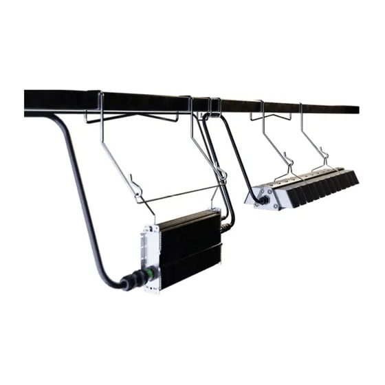
Element® L1000 Gen2
Horticulture LED Lighting System
BEFORE YOU BEGIN / AVANT DE COMMENCER
Read these instructions completely and carefully. Lisez attentivement ces instructions dans leur intégralité.
For Commercial or Industrial use only.
RISK OF SAFETY AND PRODUCT DAMAGE. DO NOT MAKE OR BREAK ELECTRICAL CONNECTION WHILE POWER IS APPLIED.
RISK OF ELECTRIC SHOCK
Turn power off before installation,
inspection, cleaning or removal.
RISK OF ELECTRIC SHOCK
• Follow appropriate lock out/tag out safety procedure.
• Properly ground electrical enclosure.
• Follow all National Electric Codes (NEC) and local codes.
• This product must be installed in accordance with the applicable
installation code by a person familiar with the construction and
operation of the product and the hazards involved.
• The installation and associated structures are subject to approval by the
authority having jurisdiction.
• Use only with components identified in this document.
• Suitable for dry, damp, and wet locations; Do not immerse any
component.
• Wear suitable Personal Protective Equipment (PPE) during installation/
maintenance. Highly recommend safety glasses, helmet and leather
glove for luminaire mounting.
• Luminaire designed for horticultural use only.
RISK OF FIRE
• Minimum 12 inch distance from light module & driver to any
combustible material.
• Minimum 6 inch clearance between, light module & driver, light
module & light module, driver & driver.
• The light module shall be installed lens down with a minimum 5 inch
distance to anything below.
• All cables including connectors shall not be concealed or extended
through a wall, floor, ceiling, or other parts of the building structure;
located above a suspended ceiling or dropped ceiling; permanently
affixed to the building structure.
• Cables shall be routed so that they are not subject to strain and are
protected from physical damage; visible over their entire length; and
used within their rated ampacity as determined for the maximum
temperature of the installed environment specified in the instructions.
• For safe operation, and to maximize the longevity of the luminaire;
ensure that the light module and driver are clean and free of dirt, dust,
oil, or any other debris. Do not apply any kind of film on the lens or
otherwise cover the driver or light engine in any way.
Suitable for operation in an ambient temperature between
32°F (0°C) and 104°F (40°C).
A mechanical ventilation or cooling system is required to
maintain the temperature within the growing space below
113°F (45°C) when the light module is in operation.
1 | V E R J U R E I N S TA L L AT I O N I N S T R U C T I O N
WARNING / AVERTISSEMENT / ADVERTENCIA
RISQUE DE CHOC ELECTRIQUE
Coupez l'alimentation avant l'installation,
l'inspection, le nettoyage ou le retrait.
Opération compatible avec un environnement à temperature ambiante
controlée entre 32°F (0°C) et 104°F (40°C).
l'utilisation d'un système de contrôle de la température sera nécessaire pour
garder la serre sous les 113°F (45°C) lorsque le luminaire est en function.
RIESGO DE SHOCK ELÉCTRICO
Apague la energía antes de la instalación,
inspección, limpieza o remoción.
RISQUE DE CHOC ELECTRIQUE
• Coupez l'alimentation avant l'inspection, l'installation ou la désinstallation.
• Reliez correctement le boîtier électrique à la mise à la terre.
• Suivre tous les codes électriques locaux applicables.
• Ce produit doit être installé selon le code d'installation pertinent, par une
personne qui connaît bien le produit et son fonctionnement ainsi que les
risques inhérents.
• L'installation et les structures associées sont soumises à l'approbation des
autorités compétentes.
• Utilisez uniquement avec les composants identifiés dans ce document.
• Convient aux endroits secs, humides et mouillés. Ne doit pas être immergé.
• Portez les équipements de protection individuelle appropriés pendant
l'installation et la maintenance. L'utilisation de lunettes de sécurité, d'un
casque et des gants de cuir pour le montage du luminaire est fortement
recommandée.
• Luminaire conçu pour horticole seulement.
RISQUE D'INCENDIE
• Distance minimale de 12 pouces entre l'équipement d'éclairage et toute
matière combustible.
• Distance minimale de 6 pouces entre tout équipement d'éclairage, module
d'éclairage ou module d'alimentation.
• Le luminaire doit être installé avec l'objectif pointé vers le bas avec une
distance minimale de 5 pouces entre le luminaire et tout objet.
• Les câbles et connecteurs ne doivent pas être dissimulés à l'intérieur, ou
passer à travers, d'un mur, d'un plancher, d'un plafond ou de toute autre
partie de la structure du bâtiment; ne doivent pas être placés au-dessus
d'un plafond suspendu; ne doivent pas faire partie intégrante de la structure
du bâtiment.
• Les câbles doivent être installés de façon à être protégés contre l'étirement
et tout autre bris physique; visibles sur toute leur longueur; utilisés dans
la limite de leur courant admissible, déterminée pour les limites de
température de l'environnement spécifiées dans le guide d'instruction.
• Pour une opération sécurisée et pour maximiser la longévité du luminaire;
S'assurer que le module d'éclairage et le module d'alimentation sont
propres et sans saleté, poussière, huile ou autres débris. Ne pas appliquer
tout type de film sur les lentilles et ne pas couvrir le module d'alimentation
ou le module d'éclairage de quelconque manière.
Installation Guide
Installation Guide
Installation Guide
912-00504-001
HORT150 | 99009069
XXXXXX | A-XXXXX
Advertisement
Table of Contents

Related Manuals for Acuity Brands Element L1000 Gen2


Summary of Contents for Acuity Brands Element L1000 Gen2
- Page 1 Installation Guide Installation Guide Installation Guide 912-00504-001 HORT150 | 99009069 XXXXXX | A-XXXXX Element® L1000 Gen2 Horticulture LED Lighting System BEFORE YOU BEGIN / AVANT DE COMMENCER Read these instructions completely and carefully. Lisez attentivement ces instructions dans leur intégralité. For Commercial or Industrial use only.
-
Page 2: Driver Specifications
Installation Guide 912-00504-001 System Component Parts AC cable Driver Driver Bracket Hanger (2x) Light Module Brackets (2x) Light Module Please refer to order logic to determine whether item is included or an accessory Light Module Specifications System Input Current [A] System Input Current [A] Low Voltage Driver High Voltage Driver... - Page 3 Installation Guide 912-00504-001 Interconnection Cables Specifications Ordering Nomenclature Detailed Description VACNPQDAC4FT AC Leader Cable, 4ft, UL VACPQDTL4FT 8-20P AC Leader Cable, 4ft, 16AWG, NEMA L8-20, UL VACPQDTL4FT 7-15P AC Leader Cable, 4ft, 16AWG, NEMA L7-15, UL VACPQDTL20A4FT L7-20P AC Leader Cable, 4ft, 16AWG, NEMA L7-20P, UL VACPQDSB4FT 5-15P AC Leader Cable, 4ft, NEMA 5-15, UL RK8VAE QDAC CORD CONN...
- Page 4 Installation Guide 912-00504-001 1 INSTALLATION OF THE LIGHT MODULE 1.1 Installation of Module Brackets If not preassembled, install light module brackets on light module. Install brackets at location A. Slide down bracket along channels. SNAP! SNAP! Press down on bracket until hooks snap into place.
- Page 5 Installation Guide 912-00504-001 1.2 Selection of Mounting Hardware Based on the cross section of the structural member select the correct hanger or mounting cable. Unistrut 1-5/8" (41mm) Square 2-3/4" (70mm) Other Structural Members Use standard hanger 1-5/8" (41mm) Use standard hanger Use 18"...
- Page 6 Installation Guide 912-00504-001 1.4 Installation with Universal Cables Loop Hook Attach hooks to light module brackets. Ensure Wrap loop end of cable over structural member. hook gate is closed. Insert hook through loop end. 1.5 Installation with Perpendicular 90° Universal Mounting Kit Kits Contents (SKU: 93139057) 1x Worm Drive Clamp 6 ft.
- Page 7 Installation Guide 912-00504-001 Installation Steps for Perpendicular 90° Universal Mounting Kit First determine which 2 slots on Secure the metal bracket on Place the metal bracket on the metal bracket most closely to the top of the structural top of the structural member correspond to the structural member by inserting the strap and wrap the strap around...
-
Page 8: Installation Of The Driver
Installation Guide 912-00504-001 2 INSTALLATION OF THE DRIVER 2.1 Installation of Driver Bracket If not preassembled, install driver bracket onto driver. Bracket Orient driver perpendicular to the bracket. Ensure first end of bracket hook is lined up with oval mounting hole of driver. Squeeze bracket arms together &... - Page 9 Installation Guide 912-00504-001 2.2 Selection of Mounting Hardware Based on the cross section of the structural member select the correct hanger or mounting cable. Unistrut 1-5/8" (41mm) Square 2-3/4" (70mm) Other Structural Members Use standard hanger 1-5/8" (41mm) Use standard hanger Use 18"...
- Page 10 Installation Guide 912-00504-001 2.4 Installation with Universal Cables Loop Hook Attach hooks to oval driver mounting holes. Wrap loop end of cable over structural member. Ensure hook gate is closed. Insert hook through loop end. 2.5 Installation with Custom Brackets If you choose to use your own custom mounting method, attach to oval driver mounting holes A and B for hanging.
-
Page 11: Electrical Connections
Installation Guide 912-00504-001 3 ELECTRICAL CONNECTIONS Dimming Amphenol P/N: AD-03PMMS-QC8001 / Male DC Output AC Input Weiland P/N: 96.032.1055.7 / Male Driver connections 3.1 Connect the Driver Output to Light Module CLICK! Align keying features of larger Push connectors together Recommended: secure light output connector on driver until the lock ring has... - Page 12 Installation Guide 912-00504-001 WARNING / AVERTISSEMENT RISK OF ELECTRIC SHOCK RISQUE DE CHOC ÉLECTRIQUE Turn power OFF before inspection, installation or removal. Coupez l’alimentation avant l’inspection, l’installation ou la désinstallation. 3.2.1 Connect the Driver Input CLICK! Align keying features on driver Push connectors together until Recommended: secure AC with connector on the selected...
-
Page 13: Connection Schematic
Installation Guide 912-00504-001 3.3 Connection Schematic 3-Phase Y 3-Phase ∆ AC line Use proper circuit protection level Driver Input Wire Colors Black = Line 1 White = Neutral or Line 2 Yellow/Green = Ground Driver Driver Driver Driver Driver Driver REPEAT FOR ENTIRE CIRCUIT BALANCING OUT EACH PHASE WARNING / *White = Neutral or Line 2... - Page 14 For the latest install guides for your product go to: https://www.acuitybrands.com/verjure-horticulture-lighting One Lithonia Way, Conyers, GA 30012 | Phone: 800.705.SERV (7378) | www.acuitybrands.com | VJ_1835752 ©2024 Acuity Brands Lighting, Inc. All rights reserved.
Need help?
Do you have a question about the Element L1000 Gen2 and is the answer not in the manual?
Questions and answers