Table of Contents
Advertisement
Quick Links
Advertisement
Table of Contents

Related Manuals for YUNEEC H600


Summary of Contents for YUNEEC H600
- Page 1 H600 H600-RTK User Manual V1.0...
-
Page 2: Table Of Contents
....................... 11 Normal Camera........................11 Thermal Imaging Camera ..................... 13 Variable-focus Camera ......................13 Yuneec Certificate Authority Payloads ................. 14 Payload Combination List ..................... 14 Payload Attaching Warnings ....................14 SD Card Selection ........................15 Attaching / Detaching the gimbals ..................15 Pre-Flight Preparation ...................... - Page 3 Control the Drone ........................33 Basic Flight Control ....................... 33 Angle Mode ........................33 Sport Mode ........................33 Manual Mode ........................33 RTL Mode .......................... 33 Quit the RTL ........................36 RTL Height ........................36 Special Note in RTL Mode ..................... 37 Precautions for the Sensors ....................
- Page 4 Center Button ......................... 100 Coaching ......................... 102 Custom Electronic Fence ....................104 Add the Fence ......................... 104 Fence Setting Menu ......................108 Breach Behavior Select ....................110 The Impact of Fence on Flight Route Editing ..............112 Execute the Flight Mission .....................
- Page 5 Battery Warnings and Usage Guidelines ................170 General Safety Precautions and Warnings ................. 171 FCC Statement ........................172 RF Exposure Warning ......................173 IC Radiation Exposure Statement for Canada ..............173 CE WARNING STATEMENT ....................173 EU COMPLIANCE STATEMENT ..................173 Yuneec Support ........................174...
-
Page 6: Product Overview
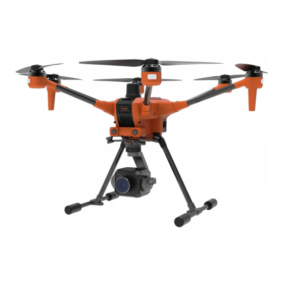
Product Overview Drone Propeller LED Status Indicator Obstacle Avoidance Lens Landing Gear Artosyn Antennas Type-C USB 3.0 Port Autopilot UART Port Micro SD Slot Battery RTK Antenna (RTK Version Only) I/O Board LED Binding Button Gimbal Port I/O Board Debug Type-A 3.0 USB Port XT30 Power Output Port (19.8V-26.4V Max 3A) Autopilot Debug Type-C USB Port... -
Page 7: T-One Transmitter
T-One Transmitter Antennas Previous Button Left Control Stick Zoom Knob Power Button 5D Button Flight Mode Switch Battery Level LEDs Home Page Button Right Control Stick Motor Start/Stop Button Return to Launch Button Type C USB Charging Port Micro SD Card Slot Headphone Port HDMI Port Video Record Button... -
Page 8: Charging The Batteries
Charging the Batteries Charging the Drone Battery Insert the plug of the YC-200 charger into a 90-264V AC outlet and the charger will be powered on automatically. Plug the drone battery into the charger port as illustrated. The batteries will charge automatically. Battery Maintenance Guide The battery should be charged and discharged at least once every 3 months. -
Page 9: Charging The T-One Battery Via Usb
3.2 High temperature charging protection: If the battery detects temperature higher than 60℃, the charging process will be stopped. 3.3 Low temperature discharging protection: If the battery inserted in the drone detects a temperature lower than 0℃, the self-heating will be started until the temperature is higher than 15℃. -
Page 10: Assembly
Assembly Assembling the Motor Arms Unfold the motor arms and secure them until hearing a 'click'. Notice: When folding the arms, the operator needs press the Press Button on the Motor Arm to release the hook first. Assembling the Propellers Mount propeller 'A' on motor 'A' and propeller 'B' on motor 'B'. -
Page 11: Payload Introduction
Normal Camera E90x/E90 Pro Yuneec’s E90x/E90 Pro camera is a one-inch CMOS sensor to capture high-quality images with 4k 10 bit in-camera color processing. Images may be captured in JPEG or DNG format, or simultaneous capture of both formats. Video may be recorded in UHD, 2K, or HD resolutions at a variety of frame rates. - Page 12 Digital Zoom Function for E90x/E90 Pro Yuneec camera E90x is capable of digital zoom. A digital zoom is an ideal tool for many types of inspection, or getting a closer view of objects further than the camera is able to originally see.
-
Page 13: Thermal Imaging Camera
Thermal Imaging Camera ETx Lite/E20Tvx/E20 Pro These series are an innovative combination of 3-axis gimbals and thermal imaging cameras. While the thermal imaging camera selectively measures the temperature in the image, enabling it to display relative temperature differences, the low-light RGB camera in the ETx Lite has a 20 times higher sensitivity than the human eye. -
Page 14: Yuneec Certificate Authority Payloads
Yuneec Certificate Authority Payloads Yuneec has several different certificate authority 3 part payloads devices for use on the drone. Get more information on www.yuneec.com. Payload Combination List Payload Type Function E90x/E90 Pro Gimbal Control, Photo Capture, Video Record, Digital Zoom... -
Page 15: Sd Card Selection
SD Card Selection Yuneec recommends using a SDXC Class 10 UHS-3 micro-SD card for recording 4k video. Using the UHS-3 card allows the camera buffer to record to the micro-SD card faster resulting in fewer buffers overrun. -
Page 16: Pre-Flight Preparation
Please make sure all firmware is the latest version. Firmware can be updated via the OTA update function, and the operator manual can be downloaded from the website: www.yuneec.com. The quick start guide does not replace the operator manual. Press and hold the Power Button on the... - Page 17 Press and hold the Power button on Drone Flight Battery to power on/off the drone. Notice: Always Power on the T-One before powering on the UAS. About 9 seconds after the drone powered off with the shutdown sound, the “Communication Lost”...
-
Page 18: Enter The Operator Id
Enter the Operator ID The operator ID enter window is the first dialog box after powered on. Tap the enter box then enter the ID via the popped up soft keyboard on the screen. Then tap the “Apply” Button to finish. Notice: If take off directly without entering the Operator ID, the user may face legal risks. -
Page 19: Calibrating The Compass
Calibrating the Compass In the following situations recalibrating the compass is suggested for flight safety: 1. Before the first flight when you take the drone out of the box; 2. When feeling the drone is drifting after a long-distance flight; 3. - Page 20 Step 3: Calibrating Follow the onscreen display and instructions. During compass calibration, the drone will need to rotate along the specific axis which is shown by the LED of each motor arm, until a tone is heard to change to the next axis. Repeat this procedure for all six positions. A yellow box with a red arrow indicates the rotation axis, which is calibrating.
-
Page 21: Cors Network Binding (Rtk Version Only)
Step 4: Reboot the drone After all axes have been calibrated, tap the “Reboot Vehicle” Button on the popped-up dialog box to activate the calibration result. CORS Network Binding (RTK Version Only): The Network CORS and RTK GPS have been disabled by the default setting. The drone will be positioned and navigated by using the single GPS technology. - Page 22 Step 2: Tap the Settings Icon, and then enter the “Vehicle” Menu. Tap the “RTK GPS” Button and select “gps rtk” Selection, after that restart the drone. Step 3: Tap the “Settings” Icon then tap “GNSS RTK”. Select “NTRIP” as the RTCM Source, then tick Auto reconnect.
- Page 23 Step 4: Fill the following “NTRIP Stream Settings” parameters according to your CORS Network. Notice: You must fill out the “Required” tagging forms. Step 5: Tap “Apply” Button to finish the connection process. Notice: When connect to the CORS Network has been successful, the “Connection Status” will display with a green “Connected”.
-
Page 24: Ugz
1. UGZ Check It is necessary to check the UAS Geo-awareness Zone (UGZ) before taking off to avoid fly enter the zone. The operator need connect the transmitter to the internet via Wi-Fi and the UGZ will be update around the drone current position in the area with 10km radius. Internet Connected The UGZ in the circle will... - Page 25 2. Buffer Zone Once the UGZ was detected the drone will generate 2 buffer zones with different safe level. Their spatial relationship is shown in the figure below: The Red Color Zone: UGZ, download from the internet. The Yellow Color Zone: 1 Level Buffer Zone, extend the vertical limitation from the UGZ with 5 meters and the horizontal limitation with 20m.
- Page 26 3.2 When in 1 Level Buffer Zone The minimum distance to the UGZ will be continuously announced with the time interval of 10 seconds and cannot be entered from outside. Normally the drone cannot enter the 1 Level Buffer Zone from outside by remote control. They will be blocked once reached the edge of the 1 Level Buffer Zone.
- Page 27 The warning messages screenshot Once the drone flies into horizontal range of the UGZ accidentally, the Landing or RTL mode will be enabled automatically in 10 seconds. The countdown will be shown in the yellow warning message. Forced RTL If the drone is flying above the UGZ, the RTL will be enabled after the countdown finished. Forced Landing While the done is flying in or under the UGZ, the forced landing will be enabled after the countdown finished.
-
Page 28: Minimum Environment Requirements
Minimum Environment Requirements 1. Space Always operate the drone in open areas (approximately 10000 square feet/930 square meters or more) that are free of people, vehicles, trees and other obstructions. Never fly near or above crowds, airports or buildings. Never attempt to operate the drone near tall buildings/obstructions that do not offer a clear view of the sky (minimum clearance of 100°). -
Page 29: Pre-Flight Checklist
5. About the TOF Height Sensor The TOF Height Sensor will take effect when the height of the drone is lower or equal to 7 meters and the flight speed is no more than 1m/s by constant measuring the distance to the ground to get a more precise and stable height control. - Page 30 Drone Part Check Item No Abnormal Sound When Rotating by Hand Motor With Proper and Uniform Damping When Rotating by Hand Able to Be Lit Functional Motor LED Be Able to Correctly Display the Current Flight Mode Check Be Able to Correctly Display the GNSS Status Get the GPS Position Lock except Indoor Flight Mode Battery Enough Power Left in the Battery...
-
Page 31: Take Off
Take Off Takeoff Mode Selection The drone has 4 different basic flight modes. We suggest placing the flight switch in the middle position to use the Angle Mode to take off. Optimal Transmission Range The signal between the drone and the T-One Transmitter is most reliable when the antennas are positioned in relation to the drone below. -
Page 32: Take Off Method 1
Take Off Method 1: After the drone was positioned by GPS, we can start the motors by pressing and holding the Motor Start/Stop Button on the T-One Transmitter and release it when the motors start. Slowly raise the Left Control Stick to take off (Mode 2 Shown). Take Off Method 2: Tap the “Takeoff”... -
Page 33: Control The Drone
Control the Drone Basic Flight Control Flight Mode Switch Overview Angle Mode When in Angle Mode and GPS is available, the drone will respond according to the T-One Transmitter. Sport Mode In Sport Mode, the drone responses are optimized for agility and speed, making it more responsive to joystick movements. - Page 34 1. Manual Active Press and hold the RTL Button on the T-One Transmitter after the drone takes off. 2. RTL Command in the flight plan Return Route 3. Low Battery Active 3.1 Remaining Flight Time and Return Requited Time Comparison The drone will calculate the remaining flight time according to the current and remaining battery capacity then compare with the time required to return based on the distance.
- Page 35 5. Geofence Breach Return If the Geofence beach behavior happened and the Geofence Failsafe was set to “Return mode” the RTL will be enabled automatically. 6. Communication Lost Return Under default settings, at the condition of the communication between the drone and transmitter was lost for 1 second, the RTL function will drive the drone back automatically.
-
Page 36: Quit The Rtl
When the period that the drone has not gets the RC signal reached the Timeout setting, the Failsafe will be enabled, and the operator will get the yellow warning popped up as shown below: If the Failsafe Action was set to “Return mode” as default, the RTL will be active. Quit the RTL 1. -
Page 37: Special Note In Rtl Mode
When the drone is below the height set, after the RTL Mode enabled, the drone will climb to the RTL height vertically first, then flying back to the return point. If the drone is flying higher than the setting value, after the RTL enabled the drone will keep the current height and flying back. - Page 38 IMU to continue flying, we still strongly recommend to land the drone as soon as possible and contact an authorized Yuneec service center for repairs. The different yellow warning messages (0# sensor fail shown) for the sub module installed in the...
-
Page 39: Go To Location Flight
Go to Location Flight After the drone has taken off with GPS lock, the operator can command the drone to fly to a specific point on the map by directly tapping on the screen. Click the “Go to location” then the tapped point will be marked on the map as the“Go here” Point. -
Page 40: Orbit Flight
Orbit Flight After the drone was taken off with GPS Lock, the operator can command the drone to fly to orbit a specific point on the map by tapping the screen directly. Tap the “Orbit at location” then the tapped point will be marked on the map as the orbit center point. -
Page 41: Roi Flight
ROI Flight After the drone has taken off with GPS Lock, operator can command the gimbal towards a specific point of interest on the map by directly tapping the screen. Select the “ROI at location” then slide to confirm, the tapped point will be marked on the map as the ROI point. -
Page 42: Indoor Flight (Without Position System)
Indoor Flight (Without Position System) When flying the drone without GPS signal, please switch to the Indoor Flight Mode first then start the motors. Step 1: After the drone and transmitter are connected tap the Settings Icon, then select the “Vehicle”... -
Page 43: Landing
Landing Environment Requirements In most cases, the takeoff point and landing point of the drone are at the same location, so the environmental requirements during takeoff also apply. However, special attention should be paid to the following points. 1. Altitude difference between landing point and take-off point. 2. -
Page 44: Quit The Auto Landing
Tap the “Land” Button then slide the slider to confirm, the drone will land directly at the current position. 2. Auto Active 2.1 At the final stage of the RLT, the drone will hover on the landing point first then continue descent the height to land. -
Page 45: Post-Flight Checklist
Post-Flight Checklist Please strictly follow this list to check after flying to ensure the safety of the drone during storage or next flight. At the same time, doing post-flight inspections will also help ensure the service life of the drone. Before Powering Off 1. -
Page 46: Rotor Emergency Mode
5 Rotor Emergency Mode The drone will enter the 5 Rotor Emergency Mode at the condition of one of all 6 motors/propellers/ESCs got failure such as: 1. A propeller lost due to the screw unfastened 2. A motor blocked to stop 3. -
Page 47: Gimbal Control
Gimbal Control Gimbal Camera Tilt Control The operator can control the tilt of the gimbal by using the Gimbal Tilt Control Knob. Rotate the knob to the left to tilt down the gimbal, and rotate the knob to the right to tilt up the gimbal. - Page 48 Step 3: Power on the T-One Transmitter and tap the “USYNC” Button to bind. Step 4: Tap the “Next” Button to start the binding process.
- Page 49 Step 5: Connecting. Step 6: Tap the “Finish” Button to finish the binding process.
-
Page 50: Datapilot 2.0 App
DataPilot 2.0 APP DataPilot ™ is an economical and efficient task planning software tailored for industry operators, which is preinstalled in the smart transmitter for all the YUNEEC commercial drones. Main Interface Overview Full-Screen Map Interface Main Interface Button Return to the main interface from any other interface by tapping this button. - Page 51 Flight Modes Indicator Display the current Flight Mode of the drone. Obstacle Avoidance Indicator After the Obstacle Avoidance is switched on, this icon will turn green to remind the operator this function is enabled. Enabled Communication Status Indicator This indicator shows 2 different communication statuses, as in the picture shown below: Gray: The drone doesn’t connect to the transmitter.
- Page 52 Drone GPS Indicator This icon displays the drone GPS status. When the icon turns green it means the drone has an ideal positioning accuracy for flight. Tap this icon to display more information of the drone GPS status. To close the dialog box, just tap other areas on the screen. Drone Battery Indicator This icon displays the remaining power and percentage of the drone flight battery.
- Page 53 Refresh the Wi-Fi hotspots Connected Wi-Fi hotspot Available Wi-Fi hotspots Slide up & down to view all hotspots Close the Wi-Fi Setting Reset All Links Menu The operator can select the wanted Wi-Fi hotspot by tapping the SSID in the available Wi-Fi hotspot list, and then enter the passwords to connect.
- Page 54 Drone Indicate the drone position and course. The L point means the Launch Point of the drone. Map /Video Switch Display the thumbnail window of the map or video link feedback. Tap to view the full-screen map or Video Link Feedback Interface. The operator can tap the Hide Icon to hide the thumbnail window, or drag the icon to...
-
Page 55: Video Link Feedback Interface
Video Link Feedback Interface After The Main Screen has been switched to the Video Link Feedback Interface, the operator will get the screen shown below: 1Camera Quick Access Menu The operator can adjust the camera parameter quickly by using this menu. Such as exposure mode, white balance, etc. - Page 56 Photo/Video Mode Switch Switch the camera mode between the photo mode and the video recording mode. Just tap the icon to switch the camera working mode. Camera in Video Mode Camera in Photo Mode Shutter/Record Button In the video recording mode, the icon is a red dot. Tap it to start recording the video and tap again to stop recording.
-
Page 57: Plan A Flight Mission
Camera Setting Button Tap this button to open the Camera Setting Menu for further settings. Notice: According to different camera types the camera setting menu could be different. Please refer to the corresponding chapter of the gimbal manual for the Camera Setting Menu instruction in detail. -
Page 58: Mission Start Setting Menu
Mission Start Setting Menu The “Mission Start” is the first step for all kinds of the flight mission. And the corresponding setting menu is located at the first entry under the “Mission” Tab. The parameters of all the following mission steps will be set according what they are in the Mission Start Setting Menu, unless the operator set the special steps separately by opening the menu behind. - Page 59 Mission Start Setting Menu Instructions 1. Waypoint alt: The global waypoint altitude setting entry for all the following waypoints. 2. Flight speed: This entry has been ticked automatically which means applied as the global waypoint speed setting for all the following plan steps. To edit or take effect of the setting, please ensure the box was ticked.
- Page 60 4. Camera Mode Menu Normally the operator need not do any setting to the Camera Mode Menu in the Mission Start Menu for global setting. Just let them what they are by default setting. The following added mission plan steps can set the suitable mode for the camera. The Camera Mode is unchecked by default setting in the Mission Start Menu, and the drop-down menu beside cannot be open.
- Page 61 6. Launch Position Normally the operator needs not to set the Launch Position manually. Just like the tip shown “Actual position set by vehicle at flight time.” when open the menu by tapping the white-down arrow. If the operator insists modify the Launch Position by their own, please unfold the menu and type in the Altitude of the Launch Point.
-
Page 62: Plan Panel Functions
Plan Panel Functions The Plan Panel allows the operator to create a new mission, save/open a mission or insert other plans (such as add a Waypoint etc.) after the selected plan step. 1. File This button was tapped automatically after the operator enters the PLAN window and the Create Plan Menu is popped up. - Page 63 1.2 Open the Mission Tap the “Open” Button and select the stored mission (the .plan file) in the transmitter. 1.3 Delete the Stored Mission Tap the Setting Icon at the right side of the .plan file then tap the “Delete” Button to delete the unwanted mission.
-
Page 64: Takeoff
1.5 Upload the Mission to the Drone The operator can tap the “Upload” Button in the Create Plan Menu. This button is equal to the “Upload” Button or the “Upload Required” Button at the upper right corner of screen. 1.6 Download the Mission from the Drone Normally if there is a mission left in the drone, the DataPilot 2.0 app will download it automatically after the communication established. - Page 65 When select the non-Blank mission the Takeoff Point will be added automatically behind the Mission Start Menu.
- Page 66 For the Blank Plan the operator need tap the “Takeoff” Button in the Plan Panel first then click in map to set planned Takeoff location. Once the Takeoff Point was set, the operator need select it first then the following mission plans will be available by lighting up in the Plan Panel.
- Page 67 2.2 Takeoff Point Altitude Setting The Altitude of the Takeoff Point will be set automatically according to what we set for the “Waypoint alt” in the Mission Start Menu. The operator can modify the value by tapping the enter box under the “Altitude” then enter the value.
- Page 68 2.3 Set the Heading of the Takeoff Point The heading of the Takeoff Point setting was off by default. The drone will keep the original heading when taking off at the vertical climb period. We do not suggest the operator to change the Heading of the Takeoff Point manually. If the special heading is needed, please tick the box before the “Heading”...
- Page 69 2.4 Delete the Takeoff Point Tap the Trash Can Icon to delete the added Takeoff Point. Normally we do not need this function, without the Takeoff Point the following plan cannot be added. 2.5 Takeoff Point Position Edit Menu Tap the Triple Horizontal Lines (Setting) Icon to open the Takeoff Point Position Edit Menu. Move to vehicle position: This selection is only available when the drone is connected with the transmitter, at the condition of an ideal GPS lock.
- Page 70 Edit position…: The position of the Takeoff Point can be set more precisely by enter the Edit Position Interface although it can be adjusted roughly by dragging directly on the map when selected. The Edit Position Interface support 3 different coordinate system as the screenshot shown below: Geographic System UTM System MGRS System...
-
Page 71: Waypoint
3. Waypoint A waypoint defines a specific location and behavior at a specific point in time, allowing for intelligent auto-functions during flight. Waypoint flight is ideal for capturing oblique images, perimeter monitoring, and many other uses. 3.1 Add Waypoints If the operator needs to plan a fight mission in a new area, connect the transmitter to the internet via a Wi-Fi hotspot to download maps. - Page 72 3.2 Waypoint User Interface Overview Selected Waypoint Parameters Display the parameters of the selected waypoint. Mission Summary Display the summary of the entire flight mission added to this map. Upload Button When a new mission was set, please tap this button to upload the mission to the drone. Selected Waypoint When a waypoint was selected, it will be marked color in green.
- Page 73 Terrain Altitude Indicator This window displays the Terrain Altitude and Waypoint Height for mission planning. Other Waypoints Takeoff Point Selected Waypoint Waypoint Number (Item #) Launch Point Terrain Altitude 11Waypoint Setting Menu This menu is the setting panel for each waypoint to adjust the waypoint parameters in detail. 3.3 Adjust the Waypoint Parameters Once a waypoint was set and selected, the screen will pop up the Waypoint Setting Menu on the right side.
- Page 74 3.4 Waypoint Position Edit Menu Be similar with the Takeoff Point Setting Menu, the Waypoint Setting Menu also has a Triple Horizontal Lines Icon to open the Position Edit Menu. Due to the Waypoint is not the 2 item of the flight mission in most cases, there is a more selection in the Waypoint Position Edit Menu.
-
Page 75: Roi
4. ROI The ROI function in the mission plan can add the Region of Interest Point on the map. Normally this function is applied in a flight mission only consisting of waypoints. After the Takeoff Point is added the ROI Point is allowed, tap the “ROI” Button in the Plan Panel on the left side of the screen then tap on the map directly to add the ROI Point and the altitude can be set in the “Region of interest (ROI)”... -
Page 76: Pattern
5. Pattern Pattern is designed for mapping and 3D scanning of ground-based objects. After the Takeoff Point is selected (on the map marked in green) the “Pattern” Button is enabled on the Plan Panel. Tap the button to open the sub menu then select a wanted pattern type to insert after the Takeoff Point. - Page 77 The selections in the Create Plan Menu almost contain all the pattern types. All the steps of a pattern fight mission will be created by just 1 tap in the Create Plan Menu. The Takeoff Point, Pattern Plans and Return To Launch steps will be insert automatically. Otherwise by using the sub menu opened by the “Pattern”...
-
Page 78: Survey Plan
5.1 Survey Plan Survey mode allows the operator to quickly place a survey grid over a desired area. To select a survey grid mission, tap the “Survey” Button in the Create Plan Menu. If the transmitter isn’t connected with the drone or the drone hasn’t the ideal GPS position the operator need adjust the Takeoff Point by their own. - Page 79 After the Takeoff Point has been set and the Survey Step has been selected, the operator can divide the survey area on the map. There are 3 preset templates to choose for editing the survey area. The operator can choose one of them for a Survey plan.
- Page 80 Vertex Precise Adjust The existed vertex of the survey area can be deleted or adjust precisely by tapping the vertex. The menu will pop up after tapping the vertex Tap the “Remove vertex” to delete the selected vertex. Tap the “Edit position…” to open the Edit Vertex Position Interface which is the similar with what used for the Takeoff Point and Waypoint.
- Page 81 After the green template covered the survey area you want on the map, please tap the “Done with Polygon” Button and then tap the “Done Adjusting” Button for the further settings. Notice: For the Trace template, please tap the “Done Tracing” First, and then tap the “Done with Polygon”...
- Page 82 Adjust the Survey Parameters After the survey area has been confirmed the operator can adjust the survey parameters. Before modifying, please ensure the correct camera is selected. To change the camera, please tap the “Camera” Tab under the selected Survey Setting Menu to choose the corresponding one. Select the Camera Different cameras have different sensor size and lens parameters.
- Page 83 Notice: There are various items in the Survey Setting Menu. The operator may need to drag the menu up and down to view all items. Overlap Front Overlap – Creates images with a percentage of each image overlapping to the front of the image.
- Page 84 Transects Angle –Drag the slider or type in the parameter to adjust the Angle of the survey grid lines. Turnaround dist – Sets the distance outside the survey for the drone to turnaround. Type in the parameters directly to adjust the distance Rotate Entry Point Button -The DataPilot 2.0 App will offer more than one solution to lead the drone to enter and exit the survey area, the operator can change the Entry and Exit Point by tapping the “Rotate Entry...
- Page 85 Options Tap the “Options” to open the drop-down menu. Hover and capture image – After this Item is ticked the drone will stop and hover and then capture the image at each capture point for better image quality. Refly at 90 Degree Offset – Overlays a secondary survey grid 90 degrees from the first survey (also known as cross-hatch).
- Page 86 Presets Tap the “Presets” Button and the operator can set the Angle or the Entry Point of the survey area. Tap the “Save Settings As New Preset” Button to create a new save. Type in the name and tap the “Save” Button to finish.
- Page 87 After the preset file name was selected tap the “Apply Preset” Button to load the parameters for the current survey area. Tap the “Delete Preset” Button to delete the selected preset files. Create the New Survey Area when Preset File Is Existed Once the transmitter detected there is the preset file exists, the last applied preset setting will be loaded automatically when creating the new survey area.
- Page 88 After tap the “Done With Polygon” Button the operator can select the existed preset files in the drop-down menu then tap the “Apply Preset” Button. Or set the Angle and Entry Point manually for this time. Once the Transects parameters were confirmed tap the “Done Adjusting” Button to finish the preliminary settings of the survey area.
-
Page 89: Corridor Scan Plan
5.2 Corridor Scan Plan Corridor Scans Roadways, power lines, train tracks, footpaths, and other narrow winding areas may be set up as “Corridor Scans.” Corridor scans enable the drone to fly long pathways with overlap for these sorts of missions. This is an example of a corridor scan To create the Corridor Scans, tap the “Corridor Scan”... - Page 90 There are 2 preset templates to choose for editing the Corridor Scan area. The operator can choose one of them for a Corridor Scan plan. Basic Preset Template Overview Tap the “Basic” Button, the App will generate a Corridor Scan area with 2 vertices.
- Page 91 After the green template covered the Corridor Scan area you want on the map, please tap the “Done with Polygon” Button for the further settings. In this image, nine vertices have been inserted, allowing the drone to follow the curvature of the roadway.
- Page 92 Adjust the Corridor Scan Grid Parameters After the camera type has been confirmed the operator can adjust the scan grid parameters. Click the “Grid” Tab under the selected Corridor Scan Setting Menu to adjust the flight route. Notice: Be similar to the Survey mode the Corridor Scan Setting Menu is shown on the right side of the screen.
-
Page 93: Structure Scan Plan
5.3 Structure Scan Plan Structure Scan A Structure Scan allows the operator to create a grid flight pattern that captures images over vertical surfaces (e.g., walls) around a structure with an arbitrary polygonal (or circular) ground footprint. Structure Scans may be combined with nadir/survey flights to better serve architects, engineers,... - Page 94 Be similar to the Survey mission, there are also 3 preset templates for the Structure Scan. The operator can choose one of them for a Structure Scan plan. Basic Preset Template Overview A green overlay will appear with four corners. Tap and hold the center dot to drag the scan area on the map.
- Page 95 A green overlay will appear which represent the scan area. The region shown in green must be modified so that it surrounds the structure and the white line indicates the flight route. • Drag the opaque vertices on the map to the edge of the structure. •...
- Page 96 Adjust the Structure Scan Parameters After the Structure Scan area and cameras has been confirmed the operator can adjust the scan parameters. Click the “Grid” Tab under the selected Structure Scan mission to adjust the flight route. Notice: The operator need drag the menu up and down to view more items. At the condition of the camera parameters have been entered the “Overlap”...
- Page 97 The Layer Height in 3D view (Gray Color) In addition to the parameters mentioned above can affect the flight route in a Structure Scan mission the rest marked in the screenshot below will also affect at the different scan period. Scan Direction Selection Tap the white-down arrow to open the menu then the operator can select start from bottom or top.
- Page 98 After the top or bottom selected the flight route will be generated combined with the “Structure Height”, “Scan Bottom Alt” and “Entrance/Exit Alt”. The Flight Route Schematic Diagram when Scan From the Top The Flight Route Schematic Diagram when Scan From the Bottom The orange line means the flight route and the arrows on the orange line means the direction.
-
Page 99: Return Button
Hover and capture image The drone will keep hover when taking the photo after ticking. This function may increase the accuracy of the scan result but take more time for a flight mission. Rotate entry point button Tap this button to switch the corner of the structure for the drone to entry and exit the scan rounds. -
Page 100: Center Button
Once the “Return” Button is tapped the “Return To Launch” step will be added at the last and the return flight route will be added on the map. Return Route To delete the “Return To Launch” command, please tap the Trash Can Icon. - Page 101 Specified Location Tap the “Specified Location” Button to open the Edit Position Interface. Be similar with the waypoints and vertexes there are 3 different coordinate systems supported in the menu. After enter the coordinate then tap the corresponding Set button then the entered coordinate position will be moved to the center of the map.
-
Page 102: Coaching
8. Coaching After the drone and transmitter are connected the “Coaching” Button will appeared on the Plan Panel. The Coaching function will allow the DataPilot 2.0 App to capture the drone current GPS position as a new waypoint. After the Takeoff Point has been set in a Blank Plan, and then tap the “Coaching” Button, the operator will enter a new interface which is specially designed for capturing the drone position and generating the waypoints. - Page 103 When all the wanted waypoints have been added, please fly the drone back and land. Then tap the Mission Route Setting Button after landed. Add a “RTL” command for safety is suggested. As same as the Waypoint function mentioned above the waypoints which added by Coaching function are also can be edited in detail.
-
Page 104: Custom Electronic Fence
Custom Electronic Fence In the PLAN window, the operator not only can create a flight mission and upload to the drone the Custom Electronic Fence is supported also. After entered the PLAN window tap the “Fence” Tab beside the “Mission” Tab to switch. Add the Fence 1. - Page 105 The operator can switch the Basic Polygon Fence to the Circular Fence by tapping the “Circular” Button in the Polygon Tools Selecting Bar. If the operator wants to insert the fence more freely, please select the “Trace” Button and tap on the map directly to add the vertex.
- Page 106 Once a Polygon Fence is inserted the operator can adjust the shape and position. • Tap and drag the center dot of the fence to move the position. • For a Circular Fence, tap and drag the dot on the right side to adjust the radius. •...
- Page 107 Beside set the fence manually the operator can also load the .KML file to define the shape of the fence. Tap the “Load KML/SHP…” Button and select the file on the popped-up menu from the right side of the screen to load. 2.
-
Page 108: Fence Setting Menu
Fence Setting Menu Once the fence is inserted the menu will appear under the corresponding fence type otherwise there is an only text “None”. Before After Inclusion: This item is checked by default setting and the drone is limited in the fence. If the drone reached the edge of the fence from inside the system would consider the breach behavior happened. - Page 109 Edit: The “Edit” Item is selected by default setting and all the vertexes, vertex adding button, fence position center dot and radius adjust dot (for Circular Fence only) will be displayed on the screen. The operator can switch them off by unselect the “Edit” Item. The Edit Item is Selected The Edit Item is Unselected Del Button:...
-
Page 110: Breach Behavior Select
Breach Behavior Select After the fence area is confirmed, the operator can select the breach behavior when the drone reaches the edge of the fence. Tap the Main Interface Button to return to the Home Page of the DataPilot 2.0 App and tap the Settings Button to open the menu. - Page 111 Hold mode- The drone will keep hovering after it reaches the edge of the fence, the operator needs to switch the drone to RTL Mode manually to return the drone to the Launch Point. Return mode- The drone will switch to the RTL Mode automatically after reaching the edge of the fence.
-
Page 112: The Impact Of Fence On Flight Route Editing
The Impact of Fence on Flight Route Editing If the fight route will lead the drone reach the edge of the existed fence, the drone won’t takeoff when the operator trying to start the motor and execute the mission. The yellow warning message will pop up at the upload and mission start steps. -
Page 113: Execute The Flight Mission
Execute the Flight Mission No matter what kind of flight plan was created (Including the Custom Electronic Fence), to execute the mission or enable the fence, the operator needs to upload to the drone first. Tap the “Upload Required” or “Upload” to upload to the drone. Tap the Main Interface Button to switch back from PLAN window and slide the slider to confirm. -
Page 114: Operations In Mission Flight Mode
Tap the “Apply” Button to use the camera settings to the recommanded mission settings. Then the mission will start automatically. Operations in Mission Flight Mode Pause the Flight Mission The operator can interrupt the flight mission by the following 3 method: 1. - Page 115 Continue the Flight Mission 1. Slide the slider to continue the mission directly. 2. Tap the “Action” Button and select “Continue Mission” then slide the slider to continue. Tap the “Continue Mission” Button then slide to confirm to continue the mission.
- Page 116 Change the Flight Height The flight height can be changed by the operator during a flight mission. 1. Change the Height Before Pause Tap the “Pause” Button then the Altitude Adjust Bar will appear on the right side of the screen. Slide the slider to the wanted height then slide the slider in the Pause Confirmation window the drone will stop flying ahead and climb the height vertically until reached the new setting then keep hover.
-
Page 117: Breakpoint Continuation
Land or Return in Mission Flight Tap the “Land” Button and slide to confirm then the drone lands at the current position. Tap the “Return” Button and slide to confirm then the drone returns to the Launch Point. Notice: For a mission which with gimbal attitude and camera behavior controlled by the drone automatically such as a Survey or a Scan mission, control the gimbal camera manually by using the Gimbal Tilt Control Knob and Gimbal Pan Control Knob on the T-One transmitter is not suggested. -
Page 118: Extended Menu
Due to the DataPilot 2.0 App is a cross platform flight control application, beside the H600/H600-RTK, there are many items in the Extended Menu that are designed for other types of drones such as H520E and H850 please ignore the items which are not introduce in this manual. - Page 119 Miscellaneous Language- Operator can make selections according to their own requirements in the drop-down menu. Color Scheme- The DataPilot 2.0 supports 2 different Color Schemes. Indoor Scheme will provide a dark interface meanwhile the Outdoor has a bright interface. Indoor Outdoor Map Provider and Map Type- The operator can change the Map Provider and Type according to their network speed or requirements.
- Page 120 Clear all settings on next start- Tick the checking box then tap the “Yes” Button to set the DataPilot 2.0 App to the default setting when next start. Announce battery lower than- If uncheck this item, the drone low battery warning will only be triggered by the drone after reduced to 15%.
- Page 121 Disable all data persistence- Not only will the flight data be stored in the drone, but also the telemetry data can be saved in the transmitter. This item is unchecked by default setting, if checked not only the telemetry data won’t be saved, but also the map tile will only be downloaded in cache rather than the disk when auto download in the main interface.
- Page 122 1. Save log after each flight: The log will be started to record after the motors have been armed and will be stopped after each flight. 2. Save logs even if vehicle was not armed: Once the connection established between the drone and transmitter the log saving will be started no matter whether the motors have been armed or not.
- Page 123 To delete the unwanted log, please tap the Setting Icon of each Telemetry Log and tap the “Delete” Button. After the Telemetry Log has been selected the Replay will be started automatically. Tap the Main Interface Button to return and view the replay. Operations when replaying Tap the “Pause”...
- Page 124 Tap the 1x to open the drop down menu to select the Time Compression Rate of the replay. The operator also can slide the slider on the Telemetry Log Replay Status Bar to view the wanted replay period. Current Time Total Time Tap the “Close”...
-
Page 125: Offline Maps
2. Offline Maps The Offline Maps allows the DataPilot 2.0 App store the map tile in the cache in the transmitter for working in the field without the internet. After the transmitter is connected with the internet the map will be downloaded automatically according to the drone or the transmitter GPS position. - Page 126 New Set Edit Interface Introduction Map Center Setting Button New Tile Set Name Edit Box The operator can tap this button and The operator can edit the name of the select the center position on the sub new tile set in this box. menu.
- Page 127 Downloaded Area Name Edit Box The downloaded map tile set can be imported and exported between devices. Import After tapping the “Import” Button, select an import method then tap the “Import” Button on the popped-up dialog box, and select the file to import.
-
Page 128: Version
3. Version The operator can check the Version of each module or system of the drone. If the transmitter is already connected to the internet the users can tap the “Check for Update” Button to keep the firmware up-to-date. The text “Latest” shown behind each module means this module is already up-to-date. Once the later version was detected, the operator can select the transfer mode (WIFI or USB) then tap the “update all”... -
Page 129: Vehicle
5. Vehicle The operator can reset parameters, control the motor LEDs, enable the Indoor Mode, enable the RTK GPS and check the Vehicle Info under the vehicle item. Reset Parameter button Tap the “Reset Parameters” Button first then tap the “Reset” Button. Tap the “Reboot Now”... -
Page 130: Led Control
LED Control In the cases of taking the aerial photography at night, the motor LED can influence the color effect of the photos. The operator can control the motor LED according to the following introduction. Tap the white-down arrow to open the drop-down menu then select the needed LED setting, the “LEDs On”... -
Page 131: Obstacle Avoidance Switch
Obstacle Avoidance Switch Tap the white-down arrow to open the drop-down menu to enable or disable the Obstacle Avoidance function. After the Obstacle Avoidance function enabled, the Obstacle Avoidance Indicator will flash green and the operator will get an “OBS ON” yellow warning message on the screen. Obstacle Avoidance Supported Flight Mode The Obstacle Avoidance function is only supported when the drone is in the Angle, RTL and Mission Mode. -
Page 132: Indoor Mode Button
Additional Environment Requirements for Using the Obstacle Avoidance System The Obstacle Avoidance System installed in the H600/H600-RTK needs an ideal lighting environment (from 15 lux to 10,000 lux) to ensure the Obstacle Avoidance Lens can get a correct exposure. At the scenes with drastic and rapid changes in lighting and scenes with direct exposure to strong light sources the Obstacle Avoidance System could be strongly disturbed. -
Page 133: Landing Gear Button
Landing Gear Button Tap this button to open the popped up window to enable or disable the Automatic Landing Gear function. The Automatic Landing Gear function is enabled by default setting, the landing gear will be retracted automatically after reaching 10 meters height in basic flight mode. In mission mode the landing gear cannot be controlled by the Landing Gear Switch. -
Page 134: Team Mode Button
Team Mode Button By using the Team Mode the operators can control the drone and the gimbal camera separately. This allows pilots and camera operators to concentrate on their respective tasks to create more stunning works. To enable the Team Mode function 2pcs of T-One transmitters is necessary, one of them plays the role of the Master which is in charge to control the drone flight, meanwhile the other one acts as Slave controller for gimbal and camera operating. - Page 135 Slave Wait for a while until the Local Device Name appeared on both controllers. Usually the Slave controller would display the Master device name and the Master would also display the Slave one on the screen. Tap the searched Local Device Name on the Master controller and tap the “ACCEPT” Button on the Slave controller.
- Page 136 Master Controller in Team Mode Salve Controller in Team Mode After the Team Mode the enabled the Master Controller cannot control the Gimbal Tilt and Pan until quit. But the Camera Settings can be controlled by both controllers.
- Page 137 Gimbal Control in Team Mode Gimbal Tilt Control Move the Left Control Stick of the Slave Controller to tilt the gimbal up and down. Gimbal Pan Control Move the Right Control Stick of the Slave Controller to pan the gimbal left and right. Back to the Center Be similar with the single control mode, to move the gimbal back to the center position please...
- Page 138 Quit the Team Mode Tap the Team Mode Icon no matter on the Master or Slave Controller then tap the “Team Management” Button to open the Team Mode Device Select Menu and tap the “Disconnect” Button to disconnect. Master Slave Finally disable the “Wifi P2P”...
-
Page 139: Operator Id Button
Operator ID Button Be the same as the first time the drone connected to the transmitter, the yellow Operator ID enter window will pop up to enter or change the Operator ID. Then tap the “Apply” Button to take effect. About Button Tap this button to check the Product type, Vehicle ID and HOBBS Meter. -
Page 140: Summary
Tap the “Close” Button to quit the popped up window. 6. Summary This item displays the Summary of the settings for the vehicle. -
Page 141: Rc Mode
7. RC Mode Tap to select the Joysticks Mode you wish to use. 8. Sensors The operator can check the compass status and also start the magnetometer calibration in this interface. Normally it will display a green dot. If the dot turns red the compass needs to be calibrated again. -
Page 142: Safety
9. Safety The operator can change the drone Maximum flight height, Failsafe behavior and Geo-fence via this interface. Maximum Altitude For Multicopters This value was set to 120 meters as the default setting the drone won’t climb higher after the limitation has been reached, even the operator keeps pushing the Throttle Joystick upwards. - Page 143 To adjust the flight height limitation, please tap the white-down arrow to open the drop-down menu then select the wanted setting. RC Loss Failsafe Trigger and Data Link Loss Failsafe Trigger These 2 item sections allow the operator to edit the drone behavior after the RC or Data Link Loss. For the drone please retain the “Disable”...
- Page 144 Disabled- The drone will maintain the last flight mode before the RC Loss. This selection is designed for preventing the Mission Flight Mode interrupted by the RTL behavior caused by the RC lost. For example, survey for a large area which contains the flight route very far away from the transmitter.
- Page 145 Geofence Failsafe Trigger The operator can set the Radius and Height of the Geo-fence and also the drone behavior after reaching the edge of the Geo-fence. Be different with the Custom Electronic Fence function in the PLAN window, the shape and position of the Geo-fence in the Safety Menu cannot be edited by the operator.
- Page 146 Tap the white-down arrow to open the drop-down menu then select the “Action on the breach”. Hold mode- The drone will keep hovering after it reaches the edge of the fence, the operator needs to switch the drone to RTL Mode manually to return the drone to the Launch Point. Return mode- The drone will switch to the RTL Mode automatically after reaching the edge of the fence.
- Page 147 Climb to the altitude of- The minimum height when executing the RTL. Tap the enter box then type in the value to set a new value. The 20m is the default setting. Return Point Setting- Tap the select dot directly to choose the return point. If the “Return to takeoff position”...
-
Page 148: Attachment
Attachment OTA Upgrade Connect the Transmitter with the Drone Power on the transmitter and drone then wait the connection established. Make sure that you have enough power remain in the battery to finish all the OTA upgrade steps. Notice: If the operator wants to update the gimbal and camera firmware version, please also attach the gimbal camera under the gimbal bracket and insert the SD card in the camera before power on the drone. - Page 149 Update Checking Tap the Settings Icon and enter the Version Menu then tap the "Check for Update” Button to check.
- Page 150 If there is any module version is not as the same as what uploaded in the YUNEEC OTA Server an Cloud Update Icon and a “Download” Button will appear beside. Firmware Download The users can download the firmware one by one for each module or tap the “download all”...
- Page 151 Firmware Update Once the download is finished the “Download” Button will be instead by a blue “Update” Button. Tap the “Update” Button then tap the “OK” Button the transmitter will connect to the Wi-Fi module in the drone automatically.
- Page 152 Tap the “Finish” Button to finish the connection and a green “AP H600” text will display under the Wi-Fi Icon. After the Wi-Fi is connected to the drone, tap the “Update” Button again the update will be started. Notice: Please wait patiently for the progress bar to finish, otherwise incomplete firmware will cause the corresponding sub-module to fail to start.
- Page 153 Update all the modules one by one by tapping the “Update” Button behind each module. After the modules have been updated the “Latest” Icon will instead the “Update” Button. Notice: The USB transfer mode is supported by the latest firmware version that means the operator can transfer the downloaded firmware to the drone via the USB cable to get a more stable data transfer quality.
-
Page 154: Transportation And Storage Requirements
Transportation and Storage Requirements General Precaution Because the transport case carries flight batteries and precision equipment, the owner/operator must follow the transportation and storage requirements indicated in this manual. The batteries should be securely packed and protected against short-circuits. Examine whether the package of the containers is in good condition and tighten closed before transport. - Page 155 Yellow Message Warning Text content Conclusion or Solution Failsafe behavior enabled due to the RC signal Failsafe enabled: no RC lost time longer than the setting value. The remote controller lost the signal feedback Communication Lost from the drone. Please check the antennas and Warning: Connection to vehicle lost enable the RTL mode to fly closer.
- Page 156 Upgrade Issues If there is any sub-module defected by the firmware upgrade process such as sudden power cut or progress bar blocked, please contact the Yuneec authorized service center for help. Power off Issues Plug out the battery directly, if the power off blocked. Then restart the device and check the...
- Page 157 Notice: If the failure still exists after the operator has tried the solutions list above to deal with the corresponding issue. Please contact the Yuneec authorized service center for help.
-
Page 158: Maintenance
Transmitter ✓ Verify the antennas are secure. Hand tighten if necessary ✓ Check vents for debris/dust. Vacuum if necessary. Yuneec does not recommend blowing compressed air into these vents. ✓ Check the waterproof rubbers on the joysticks, Flight Mode Switch and 5D Button Charger ✓... - Page 159 100 Flights Maintenance or per 100 hours increased in the HOBBS Meter Drone ✓ Inspect play of motors by lifting each motor and adding some pressure to the side if any motor is showing signs of play, replace ✓ Check the propellers for any cracking, stress marks, or pitting ✓...
- Page 160 ANNUAL FLIGHT MAINTENANCE: Drone ✓ Update Firmware ✓ Open shell, generally clean dust, debris ✓ Perform all actions of 100 Flight maintenance recommendations ✓ Check shell for cracks/breaks ✓ Check motherboard for cracks/breaks ✓ Inspect all legs and connectors for cracks and tight connection ✓...
- Page 161 Individual operator is only allowed to perform preliminary drone maintenance, repair or part replacement according to the methods in this guide. Other maintenance operations should be performed at Yuneec authorized service center. Otherwise, it may result in failure to assemble the parts back, reduced waterproof performance, incorrect sensor calibration, and other adverse consequences that threaten flight safety.
- Page 162 Leg from the airframe. Insert the new landing gear leg tube into the airframe then secure the landing gear leg by fasten the screws. Then push the Foam Damping (Yuneec Item) on the horizontal carbon pole. Notice: The left and right landing gear leg parts are the same (Yuneec Item).
- Page 163 Then the operator can replace the new flight battery (Yuneec Item No.) for the drone and check the battery connector. 4. Transmitter Battery Replacement Press and hold the battery release button then slide the battery downwards to remove the battery.
-
Page 164: Safeguards Compilation
20 Point Inspection after each maintenance finished Firmware Updated to current version Motor Shafts and Propellers Good Battery Slides in and makes good connection Landing gear in good condition Payload can be installed and in good condition Frame inspected for structural damage Full Transmitter System Check Battery Cells Balance normal LED Indicators checked... -
Page 165: Specification
Specification T-One Transmitter Weight 1.2kg Size 210×195×75mm Operating System Android Flight Control Software DataPilot 2.0 App Operating Frequency 2.400 - 2.4835 GHz 5.725 – 5.850 GHz Transmission Protocol 2.4GHz & 5GHz Transmission Power (EIRP) 2.4 GHz : CE<18dBm FCC <29dBm 5 GHz : CE<12dBm FCC <22dBm Max Transmitting Distance... -
Page 166: Drone
Drone Type H600 H600-RTK Weight 1600g 1630g (Without Payload & Battery) (Without Payload & Battery) Size Unfolded: 655×655×382mm Unfolded: 655×655×382mm Folded: 263×342×382mm Folded: 263×342×382mm Diagonal Size 610mm 610mm Max Angular Velocity 120°/s 120°/s Max Ascend Speed 5m/s 5m/s Max Descent Speed... -
Page 167: Battery
Battery Dimensions 180 × 78 × 74 mm Weight 1080g Number of Cells Maximum Instantaneous Discharge Current Maximum Continuous Discharge Current Standard Battery Voltage 23.1 V Maximum Charge Rate Battery Type Li-ion (3.85V per Cell) Capacity 9800mAh Energy 258.72Wh Max Resistance of the Battery 25mΩ... -
Page 168: Motor Led Introduction
Motor LED Introduction ·Initialization Failed: All LEDS ·Binding Completed: All LEDS ·Compass Calibration: All LEDS ·Other Status all refer to the 2 rear LEDs (LED 3#/4#) LED Position Introduction Fore LEDs: 1# and 6# Left LED: 2# Right LED: 5# Rear LEDs: 3# and 4# Legend: The LED is constantly on with the color in the icon. -
Page 169: Disclaimer And Statement
Disclaimer and Statement Disclaimer Yuneec International (China) Co., Ltd shall not be held liable for any damage, injury or for use of the product in violation of legal regulations, especially in the following circumstances: Damage and/or injury as well violation of legal regulations resulting from a failure to comply with the operating instructions or the instructions at www.yuneec.com, product information, user... -
Page 170: Battery Warnings And Usage Guidelines
Damage and/or injury as well as violation of legal regulations caused by flying in legally defined no-fly zones. Further losses which do not fall within the scope of use are defined by Yuneec as improper. This product is designed for both professional use and personal private use. The national and international laws and regulations in force at the time of taking off must be adhered to. -
Page 171: General Safety Precautions And Warnings
Never leave batteries, chargers and power supplies unattended during use. Never attempt to charge low voltage, ballooned/swollen, damaged or wet batteries. Never allow children less than 14 years of age to charge batteries. Never charge a battery if any of the wire leads have been damaged or shorted. Never attempt to disassemble the battery, charger or power supply. -
Page 172: Fcc Statement
Always begin to operate your aircraft with a fully charged battery. Always land as soon as possible after the first level low voltage battery warning or land immediately after the second level low voltage battery warning. Always operate your aircraft when the voltage of the battery in the transmitter/personal ground station is in a safe range (as indicated by the LED status indicator light of the transmitter/personal ground station). -
Page 173: Rf Exposure Warning
5G Wi-Fi: 5150-5250MHz (12dBm). EU COMPLIANCE STATEMENT Hereby, Yuneec International (China) Co., Ltd. declares that this device is in compliance with the essential requirements and other relevant provisions of the RED Directive 2014/53/EU. The full text of the EU Declaration of Conformity is available at the following internet address:... -
Page 174: Yuneec Support
H600/H600-RTK Yuneec Support www.yuneec.com This content is subject to change downloads the latest version from www.yuneec.com If you have any questions about this document, please contact us by Start a conversation on www.yuneec.com...
Need help?
Do you have a question about the H600 and is the answer not in the manual?
Questions and answers