
Related Manuals for YUNEEC H520E


Summary of Contents for YUNEEC H520E
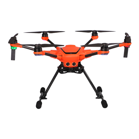
- Page 1 H520E/H520E-RTK OVERVIEW H520E/H520E-RTK Propeller OFDM Module OFDM Antennas LED Status Indicator Retractable Lander Gear RKT Antennas Battery Chamber (H520E-RTK only) RTK 天线用灰色虚线画出...
- Page 2 ST16E Start/Stop Motors Button Start/Stop Video Recording Button Gimbal Pan Mode Switch Power Switch (Follow Mode/ Follow Pan Controllable 2.4GHz Antenna Mode/ Global Mode) 5GHz Antenna Gimbal Tilt Mode Switch Proportional Control Rate Slider (Angle Mode/ Velocity Mode) Gimbal Tilt Control Slider Gimbal Pan Control Knob Battery Throttle/ Altitude Control (Mode 2)
- Page 3 Green Blinking : Ready to charge Red Blinking: Charging Solid Green: Charge Completed Blue Blinking / Solid: Error Notice: The batteries are a consumable material and that they have to be replaced after they show weakness. Notice: Voltage for a long time storage shall be 14.4V~15.6V range. Full charged storage is prohibited Charge the ST16E battery Charge the ST16E battery by using supplied USB cable and inserting it into the USB port on the...
-
Page 4: Assembling The Arms
] points to until the propellers locked. Cross-check to be sure propellers are properly locked in place. Installing the RTK Antenna (H520E-RTK only) Screw the Antenna onto the upper cover of the drone. Ensure the Antenna has been secured before takeoff. - Page 5 Ground Station App User Interface Over view 6 7 8 11 12 Main Interface button Drone GPS indicator Map /Video Switch Mission Route Setting Drone Battery indicator Flight Parameter Display System Setting button Wi-Fi Setting button Camera Type Warning Message button OFDM Setting button Photo/Video Mode Flight Mode Indicator...
- Page 6 RC Calibration Tap the System setting button then Select the RC Calibration Item. Then tap the Start Calibration button RC Mode Tap the System setting button then Select the RC Mode Item. Select the Joysticks mode as your wish...
- Page 7 Payload Assembly and Disassembly the X connector gimbals Assembling Step 1. Find the Unlocked Mark etched on the Gimbal Yaw Motor and align the Mark Line with the front of the damping plate. Step 2. Insert the Gimbal Yaw Motor into the damping plate and rotate it counterclockwise until the Mark Line of the Locked Mark aligns with the front of the damping plate to secure...
- Page 8 Visible light Camera E90X Yuneec’s E90X camera is a one-inch CMOS sensor to capture high quality images with 4k 10 bit in camera color processing. Images may be captured in formats of JPEG or DNG format, or simultaneous capture of both formats. Video may be recorded in UHD, 2K, or HD resolutions at a variety of frame rates.
- Page 9 Thermal imaging camera ETx/E10Tx/E10Tvx This series are innovative combination of 3-axis gimbals, thermal imaging camera and low-light camera. While the thermal imaging camera selectively measures the temperature in the image enabling it to display relative temperature differences, the low-light RGB camera has a 20 times higher sensitivity than the human eye and can still take excellent shots even in low light conditions.
-
Page 10: Sd Card Selection
Get more information on www.yuneec.com. SD CARD SELECTION Yuneec recommend using a SDXC Class 10 UHS-3 micro SD card for recording 4k video. Using the UHS-3 card allows the camera buffer to record to the micro SD card faster resulting in fewer buffers overrun. - Page 11 Power ON/OFF Turn on the ST16E, and then press the power button on H520E/H520E-RTK. Release the button when the aircraft emits a rising tune. Power the ST16E before powering on the UAS. OFDM Module Re-bind The aircraft and ST16E Ground Station are already bound out of factory. There is no need to bind them.
- Page 12 Step 3: Tap the Unbind Confirm button to finish the unbind process. Step 4: Tap the OFDM logo on the top right corner again. Step 5: Power on the drone until see the dialog box shown below. Step 6 : After initialization completes, Use a paperclip or something like a needle to push the bind button inside the right hole of the OFDM module.
- Page 13 Step 7: Tap the Next button on the ST16E screen. Step 8: Waiting for connect finished.
-
Page 14: Calibrating The Compass
Repeat this procedure for all six positions. If Compass calibration fails, ensure there are no electronic devices or metal objects within ten feet of the H520E/H520E-RTK. A yellow box with a red arrow indicates the current calibration. A green box indicates a completed position. - Page 15 During Calibration Calibration Finished Download the Map In order to download the map the ST16E need to be connected to the internet via Wi-Fi Tap the Wi-Fi mark then select a hotspot...
- Page 16 To Switching the map or video as main interface by tapping the rectangular window on the lower left corner of the screen. RTK data binding (For H520E-RTK only) Option 1 CORS Network Binding: Notice: Please download the map first then connect the ST16E to the RTK data link.
- Page 17 Step 2: Tap the Settings icon then tap GNSS RTK. Select NTRIP as the RTCM source, then tick Auto Reconnect. Step 3: Fill the following NTRIP Stream Settings parameters according to your CORS Network Notice: You must fill out the Required Tagging Form Step 4: Tap Apply to finish the connection process.
- Page 18 Option 2: RTK GPS Station Binding: The binding instruction of each RTG GPS Station will be attached with the GPS Station Kit. Please refer to the corresponding sections to bind. Take Off OPTION 1 Press and hold the START/STOP button for about 3 seconds to start the motors in angle mode.
-
Page 19: Angle Mode
Control the drone Normal Flight Control Out door flight Flight Mode Switch Overview ANGLE MODE When in Angle Mode and GPS is available, the Tips: Manual mode is not recommended for drone will respond according to the ST16E first-time pilots. Without GPS, the aircraft will remote controller. - Page 20 Indoor flight When fly the drone without GPS signal, please switch to the indoor flight mode first then start the motors Step 1: After the drone and ST16E was connected tap the system setting button then select the Vehicle item, tap the Indoor Mode button. Step2: Tick the Enable Indoor Flight Step 3: Push the Flight Mode Selection Switch to the Manual Flight Mode then press and hold the START/STOP button for about 3 seconds to start the motors.
-
Page 21: Gimbal C Amera Tilt C Ontrol
Gimbal Control GIMBAL C AMERA TILT C ONTROL There is a gimbal tilt mode switch on ST16E. When the switch is in up/middle position, the gimbal camera is in Tilt Angle Mode. Use the Gimbal Tilt Control Slider on the left side of the ST16 to set the tilt position of the gimbal camera. - Page 22 Mission Flight Mode To enter Mission planning mode, tap the Mission Route Setting icon[ ] on the top of the DataPilot™ home screen. The PLAN window will open, allowing users to create Waypoint and Survey missions, sync missions between desktop, ST16E, and the drone, store/recall missions, and Center a mission around a particular point on the ST16E screen.
- Page 23 Waypoint Setting Panel Once a waypoint was set and selected, the screen will pop up the Way point Setting Panel on the right side. In this panel almost every parameter of a waypoint can be set freely, such as Altitude, Flight speed, Hold Time, etc.
- Page 24 Pattern Pattern is designed for mapping and 3D scanning of ground-based objects. Survey Mode Survey mode allows the Pilot to quickly place a survey grid over a desired area. To select a survey grid mission, tap the Pattern Icon in the Plan panel and select Survey function. This will place a green survey grid in the middle of the screen over the map.
- Page 25 Notice: As same as the Waypoint function there is also a Survey Setting Panel on the right side. Through this panel users can set all the Survey parameters. Drag the panel up and down to view more items. CORRIDOR SCANS Roadways, power lines, train tracks, footpaths, and other narrow winding areas may be set up as “corridor scans.”...
- Page 26 The CORRIDOR SCAN Setting Panel will open with a base, straight, CORRIDOR SCAN in place The small “+” symbol in the vertex allows additional vertices to be created/inserted in the pathway, allowing for numerous angles to follow the road (as seen in the image on the previous page).The aircraft will fly the white lines detailed in the pathway.
- Page 27 STRUCTURE SCANS A Structure Scan allows users to create a grid flight pattern that captures images over vertical surfaces (e.g. walls) around a structure with an arbitrary polygonal (or circular) ground footprint. Structure Scans may be combined with nadir/survey flights to better serve architects, engineers, and construction companies looking to create accurate 3D models, or output .las files to...
- Page 28 • Drag the opaque vertices on the map to the edge of the structure. • If the structure footprint is more than a simple square, click the semi-transparent circles between the vertices to create a new vertex. This allows for complex shapes such as the one seen above.
- Page 29 Execute the Flight Mission In the condition of GPS Locked in Angel Flight Mode, after the flight path has been uploaded to the drone tap the Main Interface button [ ] to switch back then slide the slider. The drone will execute the mission automatically.
- Page 30 Attachment Specification Drone Type H520E H520E-RTK Weight 1856g(Without Camera) 1892g(Without Camera) Diagonal Size 520mm 520mm Max Angular Velocity 120°/s 120°/s Max Ascend Speed 4m/s 4m/s Max Descent Speed 2.5m/s 2.5m/s Max Horizontal Speed 13.5m/s 13.5m/s Max Flight Height 500m 500m...
- Page 31 Disclaimer Yuneec International (China) Co., Ltd shall not be held liable for any damage, injury or for use of the product in violation with legal regulations, especially in the following circumstances: Damage and/or injury as well violation of legal regulations resulting from a failure to comply with the operating instructions or the instructions at www.yuneec.com, product information, user...
- Page 32 Damage and/or injury as well as violation of legal regulations caused by flying in legally defined no-fly zones. Further losses which do not fall within the scope of use defined by Yuneec as improper. This product is designed for both professional use and personal private use. The national and international laws and regulations in force as the time of taking off must be adhered to.
- Page 33 Battery Warnings and Usage Guidelines WARNING: Lithium Polymer (LiPo) batteries are significantly more volatile than alkaline, NiCd or NiMH batteries. All instructions and warnings must be followed exactly to prevent property damage and/or serious injury as the mishandling of LiPo batteries can result in _re. By handling, charging or using the included LiPo battery you assume all risks associated with LiPo batteries.
- Page 34 WARNING: Failure to use this product in the intended manner as described in the quick start guide and instruction manual can result in damage to the product, property and/or cause serious injury. A Radio Controlled (RC) multirotor aircraft, APV platform, drone, etc. is not a toy! If misused it can cause serious bodily harm and damage to property.
- Page 35 RF exposure compliance. RF Exposure Warning for H520E,H520E-RTK This equipment must be installed and operated in accordance with provided instructions and the antenna(s) used for this transmitter must be installed to provide a separation distance of at least 20 cm from all persons and must not be co-located or operating in conjunction with any other antenna or transmitter.
-
Page 36: Eu Compliance Statement
波輻射性電機設備之干擾。 EU COMPLIANCE STATEMENT Hereby, Yuneec International (China) Co., Ltd. declares that this device is in compliance with the essential requirements and other relevant provisions of the RED Directive 2014/53/EU. The full text of the EU Declaration of Conformity is available at the following internet address:... - Page 37 H520E/ H520E-RTK Yuneec Support Https://yuneec.kayako.com This content subject to change downloads the latest version from www.yuneec.com If you have any questions about this document, please contact us by Start a conversation on https://yuneec.kayako.com...
Need help?
Do you have a question about the H520E and is the answer not in the manual?
Questions and answers