Advertisement
Quick Links
HUIZHOU EPEVER TECHNOLOGY CO., LTD.
※ Thank you for selecting the Tracer-CPN MPPT solar charge
controller. Please read this manual carefully before using
the product and pay attention to the safety information.
※ Do not place flammable or explosive materials around the
product, or install the product on wall made of non-heat
resistant materials, and avoid direct sunlight.
MPPT Solar Charge Controller
1. Overview
The Tracer-CPN solar charge controller adopts the advanced Maximum Power Point
Tracking charging technology. Increase the system charging efficiency yet lower the
system cost. The controller supports various batteries. With the water-proof RS485
communication port, users can view the working status and set parameters through PC
software or APP. Tracer-CPN provides reliable protection for your battery and load in
cases of disconnection. It ensures that the controller output for both the battery and load
remains constant at the equalization voltage. This feature prevents any potential harm
or damage to the battery and load system, making Tracer-CPN the ideal choice for
those seeking reliable and safe battery control. It is widely used in RVs, household
system and field monitoring.
The features are listed below:
Support lead-acid and lithium-ion batteries
Lithium battery self-activating and low-temperature protection function
Constant voltage output function
MPPT charging, with maximum DC/DC conversion efficiency of 98%
PV power limitation function
Real-time energy statistics function
Connect the IoT (Internet of Things) modules and Cloud Server to realize remote
monitoring
Built-in Bluetooth module (Only Tracer-CPN(BLE) supports)
Standard Modbus protocol, waterproof RS485 port provides a 5VDC power with
short-circuit protection
Comprehensive electronic protections
Silent and low self-consumption design
IP68 protection level
Comply with EN/IEC62109 and civilian level EMC (EN61000-6-1/3) standards
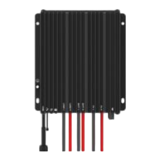
2. Appearance
⑴ The RS485 waterproof port can provide a DC power of 5VDC/200mA, and have the
short-circuit protection function. The port is isolation design for Tracer7810CPN/
Tracer7810CPN(BLE), and non-isolation design for other series. The pin definition is
shown below:
Pin
Definition
1
+5VDC
1
2
RS485-A
3
RS485-B
4
Power ground
CAUTION: When the RS485 port is not working, the waterproof cap must
be installed to prevent water from getting in.
⑵ If the temperature sensor is short-circuited or damaged, the controller shall be
charging or discharging at the default temperature of 25℃.
⑶ Only the Tracer-CPN (BLE) series are designed with the built-in Bluetooth module;
please select as you require.
3. Wiring
Connection sequence
1) Connect components to the controller in the sequence ①Battery > ②load > ③PV
as shown above and pay much attention to the "+" and "-." Please don't connect the
fast-acting fuse or circuit breaker during the installation. When disconnecting the system,
the order will be reserved.
2) The Tracer-CPN/Tracer-CPN (BLE) controllers are common-negative; all the
negative terminals can be grounded simultaneously, or anyone can be grounded.
However, according to the practical application, the negative terminals of the PV array,
battery, and load can also be ungrounded. Still, the grounding terminal on the shell must
be grounded. It effectively shields electromagnetic interference from the outside and
prevents some electric shock to the human body.
⑴
❶
RS485 waterproof port
⑵
Temperature Sensor
❷
❸
Charging Status indicator
❹
Battery Status indicator
❺
Load Positive and Negative Wires
❻
Battery Positive and Negative Wires
❼
PV Positive and Negative Wires
⑶
Built-in Bluetooth module
❽
❾
Grounding terminal
4
2
3
1
Tel: +86-752-3889706
A common-negative controller for a common-negative system, such
as the motorhome, is recommended. The controller may be damaged
if a common-positive controller is used and the positive electrode is
CAUTION
grounded in the common-negative system.
3) Connect a fast-acting fuse in series with the battery positive (+). The fast-acting fuse
must be 1.25 to 2 times the rated controller current. The installed distance is within
150mm.
4) After powering the controller, the battery LED indicator on the controller shall flash
green. If it's not green, please refer to chapter 10, Troubleshooting.
Load self-test function
The load is automatically turned ON after powering on the controller for 10s. After the
load keeps ON status for 10s, the controller restores to the set working mode.
4. LED Indicators
Indicator
Color
Status
On Solid
Green
Slowly
Flashing(1Hz)
Fast Flashing(4Hz)
On Solid
Slowly
Green
Flashing(1Hz)
Fast Flashing(4Hz)
Orange
On Solid
On Solid
Red
Fast Flashing(4Hz)
Charging indicator(green) and battery
indicator(orange) flashing simultaneously
※When connecting with a lithium battery, the controller does not recognize the
system voltage automatically.
5. Load Working Mode
1) Manual Mode (Default ON)
2) Light ON/OFF
3) Light ON+ Timer
4) Real-time Control
Control the load ON/OFF time by setting a real-time clock.
In the Light ON/OFF and Light ON/Timer modes, the Load is turned
on after 10 minutes.
CAUTION
6. Accessories (optional) and Software
1)PC software download: www.epever.com > "Solar Guardian Power Management
Installation"
2)APP download:
iOS QR code or
search for "Solar
Guardian" in the
Apple Store.
2
Website: www.epever.com
Instruction
PV connection normal but low
voltage(irradiance) from PV,
no charging
No PV voltage(night time) or
OFF
PV connection problem
In charging
PV overvoltage
Battery normal
Battery full
Battery overvoltage
Battery under voltage
Battery over-discharged
Battery overheating
Lithium battery low
temperature
System voltage error※
Turn-On voltage (Adjustable):
5V (12Vsystem), delay10min.
Turn-Off voltage (Adjustable):
6V (12Vsystem), delay10min.
Note: 24V system voltage×2
Android QR
code
Advertisement

Related Manuals for Epever Tracer-CPN


Summary of Contents for Epever Tracer-CPN
- Page 1 This feature prevents any potential harm or damage to the battery and load system, making Tracer-CPN the ideal choice for those seeking reliable and safe battery control. It is widely used in RVs, household system and field monitoring.
- Page 2 The controller is protected against small high-voltage transients. In lightning-prone areas, additional external arrester is recommended. Note: Only the Tracer-CPN series support the external Bluetooth module, the Controller Overheating Tracer-CPN (BLE) series are designed with a built-in Bluetooth module. The The controller can detect its internal temperature by the temperature sensor.
Need help?
Do you have a question about the Tracer-CPN and is the answer not in the manual?
Questions and answers