Sennheiser EM 3731 Instructions For Use Manual
True diversity receiver
Hide thumbs
Also See for EM 3731:
- Instructions for use manual (269 pages) ,
- Manual (2 pages) ,
- Brochure & specs (8 pages)

Related Manuals for Sennheiser EM 3731


Summary of Contents for Sennheiser EM 3731
- Page 1 EM 3731 EM 3732 EM 3732 Command Instructions for use % DEV % DEV 790.800 790.800 PEAK PEAK 03.03 BANK 03.03 BANK µV µV...
-
Page 3: Table Of Contents
Over 60 years of accumulated expertise in the design and manufacture of high-quality electro-acoustic equipment have made Sennheiser a world-leading company in this field. Please take a few moments to read these instructions carefully, as we want you to enjoy your new Sennheiser products quickly and to the fullest. -
Page 4: Important Safety Instructions
A polarized plug has two blades with one wider than the other. A grounding type plug has two blades and a third grounding prong. The wide blade or the third prong are provided for your safety. If the provided plug does not fit into your outlet, consult an electrician for replacement of the obsolete outlet. - Page 5 This symbol is intended to alert the user to the risk of electric shock if the device is opened. There are no user serviceable parts inside. Refer servicing to qualified personnel only.
-
Page 6: Delivery Includes
Delivery includes Intended use of the receiver Intended use of the EM 3731 single receiver or the EM 3732 and EM 3732 Command twin receivers includes: using the device for professional purposes, having read these instructions, especially the chapter “Important safety instructions”... -
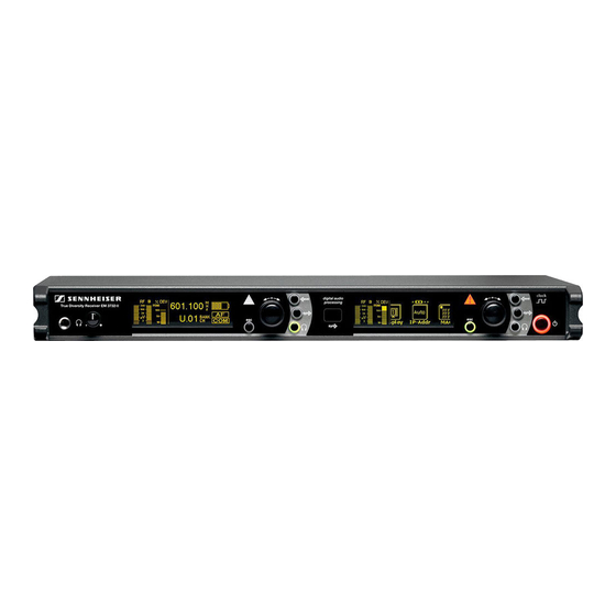
Page 7: The Em 3731/3732 Receiver Family
The EM 3731/3732 receiver family The receivers of the EM 3731/3732 receiver family ensure highest reception reliability and offer unmatched ease of use. Due to their large switching bandwidth and numerous connection options, these receivers provide maximum flexibility in daily operation. - Page 8 Distribution of the receiving frequencies within the frequency banks 1 to 6: Frequency Distribution of the receiving frequencies within the bank frequency banks The varying accumulation of frequencies within the frequency banks allows you to use as many channels as possible in a crowded frequency band.
-
Page 9: Overview Of Operating Controls
BNC socket for word clock input (75 ) *) The audio outputs marked with the number “1” output the audio signal of the left receiver of the twin receiver (as viewed from the front); the audio outputs marked with the number “2” output the audio signal of... -
Page 10: Overview Of The Display
For additional information see pages 10 and 11. Brightness control The display has an automatic brightness control. The brightness is dimmed after the last key stroke. With each new button press, the display lights up with full brightness. Triggers for dimming... -
Page 11: Indications And Displays
The receivers operate on the true diversity principle (see “Diversity reception” on page 39). The diversity display indicates whether diversity section A (i.e. antenna A) or diversity section B (i.e. antenna B) is % DEV PEAK active. The letter of the active diversity section appears backlit. -
Page 12: Status Display
Status display The status shows the receiving frequency, the transmitter battery status 790.800 and – depending on the selection made in the “Display” menu – either the frequency bank and the channel number or the name of the receiver. With NAME the EM 3732 Command receiver, the command display can also be displayed within the status display. - Page 13 Via the “Command” menu, you can configure the receiver so that – with the command button of the transmitter pressed – the audio signal is available at only one of the outputs or at both (see “Configuring the audio outputs of the EM 3732 Command twin receiver” on page 32).
- Page 14 LEDs for booster supply of antenna inputs The LEDs for booster supply of antenna input A or B light up when the booster supply voltage is applied to the corresponding antenna input A or B The LEDs for booster supply of antenna input A or B...
-
Page 15: Putting The Receiver Into Operation
Ensure that the base of the receiver is clean and free from grease before fitting the rubber feet. Fix the rubber feet to the base of the receiver by peeling off the backing paper and fitting them as shown in the diagram on the left. -
Page 16: Connecting The Antennas
Connecting the antennas CAUTION! Danger of short-circuit due to uninsulated antennas! If you switch the booster supply voltage on, a 12 V DC voltage is applied to the antennas – even when you switch the receiver off! If uninsulated antennas come into contact with objects which conduct electricity, this voltage can produce sparking and audio interference. - Page 17 When rack mounting the receiver, you require the GA 3030 AM antenna mount (available as an accessory) to mount the antenna connections to the front of the rack. The GA 3030 AM antenna mount consists of: 2 BNC extension cables (screw-in BNC socket...
-
Page 18: Daisy Chaining Up To Eight Twin Receivers
50- coaxial cable. Note: Ready-made antenna cables from Sennheiser are available as accessories with length of 1 m, 5 m and 10 m (see “Accessories/spare parts” on page 43). If you connect active antennas (e.g. A 3700, AD 3700) or antenna boosters (e.g. -
Page 19: Connecting The Receiver To The Mains/Disconnecting The Receiver From The Mains
Via the operating menu of the corresponding receiver, adjust the level of the audio output to the input of the amplifier or mixing console (see “Adjusting the audio output level” on page 31). Connecting devices with AES3 digital input... -
Page 20: Connecting An External Word Clock Generator
If you want to connect several receivers to the same Ethernet socket of your network, you require a standard 100Base-T Ethernet switch. Connect the supplied RJ 45 Ethernet cable to the RJ 45 socket for LAN connection and to your switch or network. -
Page 21: Using The Receiver
Note: If you only want to use one of the two receivers of the EM 3732 or EM 3732 Command, you can set the second receiver to standby mode (see “Setting a receiver to standby mode” on page 37). -
Page 22: Connecting The Headphones/Adjusting The Volume
True Diversity Receiver EM 3732 03.03 Connect headphones with a ¼” (6.3 mm) stereo jack plug to the headphone output To monitor the audio signals of one of the two receivers of a twin receiver: save % DEV 790.800 Press the headphone button... -
Page 23: Synchronizing The Transmitter With The Receiver Frequency
Set the receiver to the desired receiving frequency (see “Setting the receiving frequency” on page 28 and “Selecting a frequency bank and a channel” on page 28) and enter the desired name (see “Entering a name” on page 29). Press the... -
Page 24: The Operating Menu
Adjusting the squelch threshold Booster Switching the booster supply voltage on/off AF Out Adjusting the audio output level Adjusting the sampling rate of the digital audio Clock output (EM 3732 Command receiver only) Command Configuring the audio and command outputs... -
Page 25: Working With The Operating Menu
The “Tune” menu is displayed together with its current setting. The Tune Bank position of a menu within the operating menu is illustrated by a graphic in the upper display margin (the “Tune” menu is on the very left of the operating menu). Selecting a menu Turn the jog dial until the icon of the desired menu is in the center 790. -
Page 26: Operating Menu Of The Receivers
(1…6, U) and the channel (1...60) save + , - | / 0 1 2 3 4 5 6 + , - | / 0 1 2 3 4 5 6 7 8 9 * ; < = >... - Page 27 Booster AF O ooster AF Out Clock Audio output level Current audio Adjusting the audio output level output level (-10 dB to +18 dB) save 44.1 44.1 88.2 88.2 Clock Comm F Out Ext. Ext. Sampling rate of the...
- Page 28 Bank 4 5 6 U Free 32 31 33 60 Selecting a frequency bank save* Display IP-Ad After pressing the save button , the display automatically changes to the “B.Ch” menu (see page 24) – i.e. to the selected frequency bank.
- Page 29 The operating menu Selection mode Setting mode Scan Displa 790.800 790.800 NAME B.CH Display IP-Ad Status display Current status Selecting the display contents of the status display save 192. 192. 192. 0192. 168. 168. 192. 049. 168. 168. 00 1 068.
-
Page 30: Adjustment Tips For The Operating Menu
The display changes to the selection mode of the operating menu. Selecting a frequency bank and a channel B.Ch Via the “B.Ch” menu, you can select a frequency bank and a channel from the enclosed frequency tables. Change to the setting mode of the “B.Ch” menu. B.Ch The number of the frequency bank starts flashing. - Page 31 The name is stored. The display changes to the selection mode of the operating menu. In order that the name is displayed on the status display, you may have to change the contents of status display (see “Selecting the status display”...
- Page 32 It also suppresses sudden noise when there is no longer sufficient transmitter power received by the receiver. The squelch can be adjusted in 13 steps from 0 to 30 V. Selecting a smaller value reduces the squelch threshold, selecting a higher value increases the squelch threshold.
- Page 33 Out” menu, you can adjust the output level of the audio outputs (AF out and Command). With the EM 3732 Command, the audio level of the Command output 1 corresponds to the level of the audio output 1 and the audio level of the...
- Page 34 2. the command outputs Command 1 and Command 2 These audio outputs can be switched on and off via a button on the transmitter – provided that the transmitter is also equipped with the command function (a separate power pack with command button is available for the SKM 5200 transmitter).
- Page 35 Changing to the extended menu More Via the “More” menu, you can change to the extended menu with the submenus “Scan”, “Display”, “IP-Addr”, “MAC”, “Standby” and “Reset”. Scanning the frequency banks for interference-free channels Scan Via the “Scan”...
- Page 36 You can cancel the scan at any time by pressing the button . The display changes to the setting mode of the “Scan” menu and the last scan result is restored. Turn the jog dial to select a frequency bank with a sufficient number of free channels.
- Page 37 Set all transmitters of a multi-channel system to different channels within the same frequency bank. Before putting the transmission links into operation, we recommend that you perform a scan in order to find a frequency bank with a sufficient number of free channels: Switch all transmitters off.
- Page 38 IP-Addr Via the “IP-Addr” menu, you can display and change the receiver’s IP address. The IP address consists of four bytes and each byte consists of up to three digits (from 0 to 255). The receiver is factory-preset to dynamic IP addressing (“Auto”).
- Page 39 00 01 Setting a receiver to standby mode Standby You can set a receiver to standby mode and mute it. To do so, proceed as follows: Change to the setting mode of the “Standby” menu. The icon and the green backlighting of the...
-
Page 40: Additional Information
2:1 ratio (related to dB) to lift it above the inherent noise floor of the RF link. In the receiver the signal is expanded in an identical and opposite way in a 1:2 ratio to restore the original signal, at the same time reducing the RF noise to below the noise floor of the receiver. -
Page 41: Diversity Reception
The receivers operate on the “true diversity” principle: A receiving antenna receives not only the electromagnetic waves which reach it by a direct path, but also the reflections of these waves which are created in the room by walls, windows, ceilings and fittings. When these waves are superimposed, destructive interference occurs, which can also be called “field strength gaps”. -
Page 42: If A Problem Occurs
(see page 37) displayed range If a problem occurs that is not listed in the above table or if the problem cannot be solved with the proposed solution(s), please contact your local Sennheiser agent for assistance. -
Page 43: Specifications
(peak deviation, 1 kHz +18 dBu to –10 dBu, adjustable in 1-dB increments (transformer balanced) AF output sockets 1 XLR-3 socket per receiver, 2 XLR-3 sockets per EM 3732 Command receiver Headphone output 2 x 100 mW at 32 internal impedance... - Page 44 0.4 A Power consumption with receiver switched off: max. 20 W (50 VA) with receiver switched off, booster supply voltage switched on: max. 9.5 W with receiver and booster supply voltage switched off: max. 4 W Mains connector 3-pin, protection class I, as per IEC/EN 60320-1 Dimensions W x D x H [mm] 436 x 215 x 44 (without rack mount “ears”)
-
Page 45: Accessories/Spare Parts
Accessories/spare parts Accessories/spare parts The following accessories are available from your authorized dealer: Cat. No. Accessory Cat. No. Accessory 502195 A 3700 active broadband antenna 004368 GA 3030 AM antenna mount 502197 AD 3700 active broadband directional 087969 Antenna daisy chain cable, 50 , BNC, 0.25 m... -
Page 46: Manufacturer Declarations
The guarantee is void if the product is manipulated by non- authorised persons or repair stations. In the case of a claim under the terms of this guarantee, send the device, including accessories and sales receipt, to the responsible service partner. To minimise the risk of transport damage, we recommend that the original packaging is used. - Page 48 Sennheiser electronic GmbH & Co. KG Am Labor 1 30900 Wedemark, Germany Phone +49 (5130) 600 0 Printed in Germany Fax +49 (5130) 600 300 Publ. 01/08 www.sennheiser.com 516551/A01...
Need help?
Do you have a question about the EM 3731 and is the answer not in the manual?
Questions and answers