Table of Contents
Advertisement
Service
Sennheiser electronic GmbH & Co. KG • D-30900 Wedemark • Tel. 0 51 30 / 600-0
Änderungen vorbehalten / Subject to alterations / Sous réserve de modification
EM 3031-U
EM 3032-U
EM 3532-U
EM 3031-V
EM 3032-V
(Art.-Nr. / Cat no. 04555)
(Art.-Nr. / Cat no. 04556)
(Art.-Nr. / Cat no. 04400)
(Art.-Nr. / Cat no. 04365)
(Art.-Nr. / Cat no. 04201)
EM 3031, 3032, 3532
07 / 98 - 1
Advertisement
Table of Contents
Troubleshooting

Related Manuals for Sennheiser EM 3031-U


Summary of Contents for Sennheiser EM 3031-U
- Page 1 (Art.-Nr. / Cat no. 04365) EM 3032-V (Art.-Nr. / Cat no. 04201) Sennheiser electronic GmbH & Co. KG • D-30900 Wedemark • Tel. 0 51 30 / 600-0 EM 3031, 3032, 3532 07 / 98 - 1 Änderungen vorbehalten / Subject to alterations / Sous réserve de modification...
- Page 2 Sicherheitsvorschriften / Safety requirements/ Prescrizioni de sicurezza / Prescriptions de sécurité / Prescripciones de seguridad Deutsch Achtung: Bei Eingriffen in das Gerät sind die Sicherheitsvorschriften nach VDE 701 (reparaturbezogen) bzw. VDE 0860 / IEC 65 (gerätebezogen) zu beachten ! Bauteile nach IEC- bzw. VDE-Richtlinien ! Im Ersatzfall nur Teile mit gleicher Spezifikation verwenden ! MOS - Vorschriften beim Umgang mit MOS - Bauteilen beachten ! English...
-
Page 3: Table Of Contents
INHALTSVERZEICHNIS SEITE TABLE OF CONTENTS PAGE ALLGEMEINES GENERAL INHALT DER SERVICE-ANLEITUNG CONTENTS SERVICE-KONZEPT SERVICING KURZBESCHREIBUNG BRIEF DESCRIPTION VARIANTEN VARIANTS MERKMALE FEATURES BEDIENUNGSELEMENTE OPERATING CONTROLS FRONTSEITE FRONT SIDE RÜCKSEITE REAR SIDE TECHNISCHE DATEN TECHNICAL DATA MESSGERÄTE UND PRÜFMITTEL MEASURING AND TEST EQUIPMENT SPEZIELLE SERVICE-HILSMITTEL SPECIAL SERVICE TOOLS SERVICE-SET SEPT2... -
Page 4: Allgemeines
1 ALLGEMEINES 1 GENERAL 1.1 INHALT DER SERVICE-ANLEITUNG 1.1 CONTENTS Eine Reparatur der Mikroport Empfänger EM 3031, EM 3032 This service manual contains instructions for troubleshooting und EM 3532 kann durch Baugruppentausch (bzw. Modul- and repairing the EM 3031, EM 3032 and EM 3532 Mikroport tausch) vorgenommen werden. -
Page 5: Service-Konzept
Fast service means that all assemblies on the spare parts Module der Ersatzteilliste vorrätig sind. Diese können über list have to be held in stock. They can be ordered from the den Sennheiser Service bezogen werden. Sennheiser Service Department. 1.2.4 SMD (Surface Mounted Devices) 1.2.4 SMDs (Surface Mounted Devices) -
Page 6: Kurzbeschreibung
2 BRIEF DESCRIPTION Die HF-Empfänger EM 3031, EM 3032 und EM 3532 bieten With the EM 3031, EM 3032 and EM 3532 receivers, Sennheiser dem professionellen Anwender hohe Betriebssicherheit, ein- offers the professional user high quality RF receivers with a fache und komfortable Bedienung, die in Verbindung mit den high level of operational reliability and ease of use. -
Page 7: Bedienungselemente
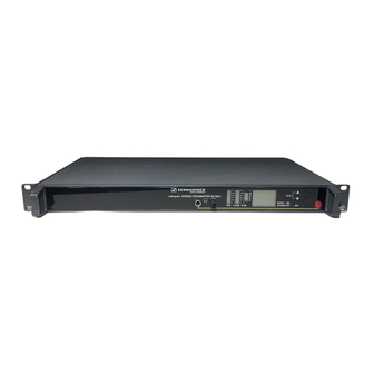
3 BEDIENUNGSELEMENTE 3 OPERATING CONTROLS 3.1 FRONTSEITE 3.1 FRONT SIDE 6 7 8 9 10 11 6 7 8 9 10 11 6 7 8 9 10 11 6 7 8 9 10 11 6 7 8 9 10 11 Kopfhörerausgangsbuchse (6,35 mm Klinke) Headphone socket 1/4"... -
Page 8: Rückseite
3.2 RÜCKSEITE 3.2 REAR SIDE Fuse holder and mains voltage selector Sicherungshalter und Umschalter der Netzspannung 2-pin IEC mains connector Netzanschluß (2-poliger Kaltgeräteeinbaustecker) Squelch control, 0 - 100 µV (SQUELCH) Rauschsperreneinsteller, 0 - 100 µV (SQUELCH) Service interface (CONFIG INPUT) Service-/Programmierbuchse (CONFIG INPUT) NF-Ausgang, symmetrisch, XLR-3 (AF OUT) AF output, XLR-3, balanced (AF OUT) -
Page 9: Technische Daten
Abmessungen (ohne Montagewinkel) ..........436 x 228 x 43 mm (19", 1 HE) Gewicht ....................EM 3031: ca. 3300 g EM 3032, EM 3532: ca. 4000 g BTZ-Nummer ..................EM 3031-U: A 128 308H RF EM 3032-U: A 128 310H RF Konformitätsnorm ................EM 3532-U: ETS 300 445... -
Page 10: Technical Data
4 TECHNICAL DATA Frequency range ................UHF: 430 MHz - 960 MHz VHF: 138 MHz - 260 MHz Switching bandwidth ................UHF: 24 MHz VHF: 7 MHz Frequency stability ................UHF: ± 10 ppm (- 10 °C to + 55 °C) VHF: ±... -
Page 11: Messgeräte Und Prüfmittel
1 Frequenzmeßgerät (z.B. HEB Digicount) 1 Frequency meter (e.g. HEB Digicount) 1 NF-Multimeter (z.B. Sennheiser UPM 550-1) 1 AF multimeter (e.g. Sennheiser UPM 550-1) 1 Oszilloskop (z.B. Hameg 605) 1 Oscilloscope (e.g. Hameg 605) 1 Voltmeter Ri ≥ 1 MΩ / V (z.B. Thandar TM 351) 1 Voltmeter Ri ≥... -
Page 12: Systemübersicht
Gerätebezeichnung Artikelnummer Frequenzbereich Schaltbandbreite Empfänger1 Empfänger2 DC-Speisung S-MCD Product name Catalog no. Frequency range Switching bandwidth Receiver1 Receiver2 DC powering S-MCD EM 3031-U 04555 434 - 960 MHz 24 MHz – – EM 3032-U 04556 434 - 960 MHz 24 MHz... -
Page 13: Service Hinweise
7 SERVICE HINWEISE 7 SERVICE INSTRUCTIONS 7.1 ALLGEMEINES ÜBERPRÜFEN 7.1 GENERAL TEST Zur Eingrenzung von Fehlern empfiehlt es sich den Empfänger To narrow down the possible causes of faults, it is advisable to mit einem funktionsfähigen Sender (z.B. SKM 3072/SKM 5000) test the receiver with an operational transmitter (e.g. -
Page 14: Abgleich Und Fehlersuche
7.3 ABGLEICH UND FEHLERSUCHE 7.3 ALIGNMENT AND TROUBLESHOOTING Zum Abgleich und zur Reparatur ist das Gehäuse der Empfänger For alignment or repairs the receivers have to be disassembled. zu demontieren. 1. Gehäuse öffnen; dazu mit Schraubendreher zwei Schrauben 1. For opening the housing, unlock two screws (1) on the rear (1) auf der Rückseite des Chassis lösen und entfernen. -
Page 15: Fehlermeldungen Em 3532-U
ERR 3: Falsches Tuner-Modul im Empfänger. Geräte arbeiten ERR 3: Wrong tuner assembly in the receiver. Receivers only nur mit EM 3031-U, 3032-U, EM 3031-V, 3032-V oder work with tuner assemblies configured for EM 3031-U, SPARE30-U, SPARE30-V konfigurierten Tuner-Modulen. -
Page 16: Modifikationen 16
8 MODIFIKATIONEN 8 MODIFICATIONS 8.1 FREQUENCIES WITHIN THE SWITCHING 8.1 FREQUENZEN INNERHALB DER SCHALT- BANDBREITE BANDWIDTH Achtung: Während das Programmierkabel M-SePT2 PH auf der Attention: Do not use the switches "SET", "UP", and "DOWN" on Empfängerschnittstelle "CONFIG INPUT" gesteckt ist, nicht die the front panel while the programming cable M-SePT2 PH is Bedienelemente "SET", "UP"... - Page 17 Empfänger Receiver IBM compatible M-SePT2 PH SePT.EXE V3.0 Service adaptor programming tool Windows ≥ V3.1 5. Programm SePT.EXE (ab V3.0) unter Windows starten. 5. Start the SePT.EXE programming tool (V3.0 or later) under Windows. 6. Die Daten des EEPROM's werden ausgelesen und im Programmfenster angezeigt.
-
Page 18: Em 3031/32 Tuner-Modul Austauschen
überprüfen. 8b. Ist das UHF-Tuner-Modul A001 ein Ersatzteil vom Sennheiser 8b. If the UHF tuner assembly (A001) is a spare part from Service, ist es auf eine Schaltbandbreite von 24 MHz in der Sennheiser Service Department, it is aligned to a switching Mitte des bestückten HF-Teils abgeglichen. - Page 19 R505 mounted Bereich Nr. 5: 798 - 960 MHz R505 bestückt The replacement tuner assembly for the EM 3031-U and Das Ersatz-Tuner-Modul für die Empfänger EM 3031-U und EM 3032-U receivers is described with "SPARE30-U". EM 3032-U ist beschrieben mit "SPARE30-U".
-
Page 20: Em 3532-U Tuner-Modul Austauschen
20. Da sich die programmierten Frequenzen außerhalb der 20. As the programmed frequencies are outside the previous alten Schaltbandbreite , aber innerhalb der Grenzen des switching bandwidth but within the limits determined by bestückten HF-Teils (RF-Amplifier, VCO, Buffer) befinden, the components of the RF section (RF amplifier, VCO, ist ein Neuabgleich laut Prüf- und Abgleichanweisung erfor- buffer), the receiver has to be re-aligned according to the derlich. - Page 21 Sennheiser Service Department, it is aligned to a switching Mitte des bestückten HF-Teils abgeglichen und für den bandwidth of 24 MHz. This assembly is prepared for use in Einsatz in den Empfängern EM 3031-U und EM 3032-U EM 3031-U and EM 3032-U receivers. konfiguriert.
-
Page 22: Dc-Speisebuchse Nachrüsten
26. Programm SePT.EXE (ab V3.0) unter Windows starten. 26. Start the SePT.EXE programming tool (V3.0 or later) under Windows. 27. Die Daten des EEPROM's werden ausgelesen und im Programmfenster angezeigt. 27. SePT.EXE reads in and displays the receiver's EEPROM data. 28. -
Page 23: Em 3032-U Auf Em 3532-U Upgraden
3. Kontaktstifte P4 und P9 auf der rechten Hauptplatine (Leiter- 3. Mount the P4 and P9 connector pins on the right main PCB platte mit dem Netztransformator) bestücken. (PCB with mains transformer). 4. XLR-4 Einbaustecker mit Kreuzschlitzschrauben in der Rück- 4. - Page 24 3. Remove the handles; for this purpose, loosen the screws 3. Griffe entfernen; dazu Schrauben von rechtem und linken Seitenblech lösen. on the left side and the right side of the side panel. 4. Prozessor-Module A015 (ASSY5) aus Empfänger RX1 und 4.
-
Page 25: Verdrahtung Für S-Mcd Betrieb
8.7 VERDRAHTUNG FÜR S-MCD BETRIEB 8.7 WIRING FOR S-MCD OPERATION KX 3500, ARTIKELNUMMER 04619, VERDRAHTUNGSPLAN KX 3500, CATALOG NUMBER 04619, WIRING DIAGRAM EM 3532-U/PC KABEL, ERSATZTEILNUMMER 75525, VERDRAHTUNGSPLAN EM 3532-U/PC CABLE, SPARE PART NUMBER 75525, WIRING DIAGRAM EM 3031, 3032, 3532 07 / 98 - 25... -
Page 26: Prüf- Und Abgleichanweisung
9 PRÜF- UND ABGLEICHANWEISUNG 9 TEST AND ALIGNMENT INSTRUCTIONS 9.1 MESSAUFBAU 9.1 TEST SET-UP Spektrum - Analysator / Spectrum analyser Oszilloskop / Oscilloscope HF - Generator / RF generator Tracking - Generator / Tracking generator NF - Multimeter / AF meter Receiver EM 3031 / EM 3032 / EM 3532-U siehe Prüf- und Abgleichanweisung Please see test and alignment instructions... -
Page 27: Module
9.2 MODULE 9.2 ASSEMBLY LOCATION HDP-MODUL (Kapitel 17) HAUPTPLATINE (Kapitel 11) HDP ASSEMBLY (chapter 17) MAIN PCB (chapter 11) DC/DC-MODUL (Kapitel 19) DC/DC ASSEMBLY (chapter 19) ANZEIGE-MODUL (Kapitel 18) DISPLAY ASSEMBLY (chapter 18) SCHALT-MODUL (Kapitel 16) DIVERSITY ASSEMBLY (chapter 16) TUNER-MODUL (Kapitel 14 und 20) PROZESSOR-MODUL (Kapitel 21 und 22) TUNER ASSEMBLY (chapter 14 and 20) -
Page 28: Prüf- Und Abgleichanweisung
9.3 PRÜF- UND ABGLEICHANWEISUNG ß ä r ü " , " S " , " A " " . H " " . ± ± ± ± e i l ß ± e i l ß ± S " " T D "... - Page 29 l l i … … o l l ä µ d l i … o l l µ d l i … 2 dB - 62 dBm Abbildung 1 nur VHF (Modul A012) 7 MHz ä t o l l d l i µ...
- Page 30 o l l µ , V o l l µ , V A " " A µ , V A " " B µ , V i l l . l a µ , V ä f e l l P ≠...
- Page 31 o l l o l l ) - ( o l l D " " D " " K µ , V ß ä r o l l µ , V o l l d l i Abbildung 4 25ms 50ms ±...
- Page 32 o l l ≥ . f f ≥ ≥ o l l ≥ . f f ≥ ≥ r r i r r i ß ä r < o l l r r i r r i ß ä r <...
-
Page 33: Test And Alignment Instructions
9.3 TEST AND ALIGNMENT INSTRUCTIONS " , " S " , " A " " . H " " . ± ± ± ± i c - ± i c - ± S " " T D " " N S "... - Page 34 o l l µV … u l l o l l µV u l l … 2 dB - 62 dBm Illustration 1 VHF assembly A012 only 7 MHz i f i l o l l u l l µ , V i f i l o l l u l l...
- Page 35 o l l µ , V o l l µ , V A " " A µ , V A " " B µ , V P ≠ 8 , y l y l l . l a µ , V a l l e l l S "...
- Page 36 o l l o l l ) - ( o l l D " " D " " K µ , V o l l µ , V o l l u l l Illustration 4 25ms 50ms ± A " ;...
- Page 37 - l a o l l ≥ ≥ ≥ - l a o l l ≥ ≥ ≥ l l a o l l < l l a o l l < o l l ) s i ≤ … o l l ) s i ≤...
-
Page 38: Baugruppenträger 38
10 BAUGRUPPENTRÄGER 10 MAINFRAME 10.1 ALLGEMEINES 10.1 GENERAL Die Geräte EM 3031,EM 3032 und EM 3532 sind Empfänger The EM 3031,EM 3032 and EM 3532 receivers together with in 19" Bauweise und dienen als Gegenstation für drahtlose Mi- the suitable hand-held and pocket transmitters permit wireless krofone. - Page 39 gelb / yellow orange / orange schwarz / black rot / red Netzstecker Mains plug EM 3031, VERDRAHTUNG gelb schwarz orange EM 3031, WIRING yellow black orange...
- Page 40 gelb / yellow orange / orange schwarz / black rot / red Netzstecker Mains plug EM 3032, VERDRAHTUNG gelb schwarz orange EM 3032, WIRING yellow black orange...
- Page 41 gelb / yellow orange / orange schwarz / black rot / red rot / red DC-Eingangsbuchse Netzstecker DC input socket Mains plug blau / blue EM 3532-U, VERDRAHTUNG gelb schwarz orange EM 3532-U, WIRING yellow black orange...
- Page 42 EM 3031, 3032, 3532 07 / 98 - 42...
-
Page 43: Hauptplatine
11 HAUPTPLATINE 11 MAIN BOARD 11.1 BESCHREIBUNG 11.1 DESCRIPTION Die Hauptplatine mit den Abmessungen 208 x 190 mm dient The main PCB with the dimensions 208 x 190 mm serves as a als Trägerplatine für einen kompletten Empfänger. carrier circuit board for a complete receiver. Sie nimmt sämtliche Module und Schnittstellen zu externen It accommodates all assemblies and all interfaces to external Anschlüssen, sowie Bedien- und Anzeigeelemente auf. - Page 44 HAUPTPLATINE, STROMLAUFPLAN MAIN BOARD, CIRCUIT DIAGRAM...
- Page 45 HAUPTPLATINE, GEDRUCKTE SCHALTUNG, BESTÜCKUNGSSEITE MAIN BOARD, PRINTED CIRCUIT BOARD, COMPONENT SIDE...
- Page 46 HAUPTPLATINE, GEDRUCKTE SCHALTUNG, LÖTSEITE MAIN BOARD, PRINTED CIRCUIT BOARD, SOLDER SIDE...
-
Page 47: Explosionszeichnung 47
12 EXPLOSIONSZEICHNUNG 12 EXPLODED VIEW EM 3031 EM 3031, 3032, 3532 07 / 98 - 47... - Page 48 EM 3032 EM 3031, 3032, 3532 07 / 98 - 48...
- Page 49 EM 3532-U EM 3031, 3032, 3532 07 / 98 - 49...
-
Page 50: Ersatzteile 50
13 ERSATZTEILE 13 SPARE PARTS IDENT BEZEICHNUNG DESCRIPTION 22996 Linsenschraube M3x6 ISO7045 Lens screw M3x6 ISO7045 22639 Federscheibe A3 DIN137 Spring washer A3 DIN137 003A 73759 Rückwand EM3031 Rear panel EM3031 003B 57556 Rückwand EM3032/EM3532 Rear panel EM3032/EM3532 53276 Linsenschraube CM3x6 DIN7500 Lens screw CM3x6 DIN7500 57530 Frontprofil... - Page 51 IDENT BEZEICHNUNG DESCRIPTION C003 45239 SMD Kondensator KERKO 150nF 50V X7R SMD capacitor KERKO 150nF 50V X7R C004 45239 SMD Kondensator KERKO 150nF 50V X7R SMD capacitor KERKO 150nF 50V X7R C005 24149 Kondensator AL-ELKO 220uF 10V GPF Capacitor AL-ELKO 220uF 10V GPF C006 45239 SMD Kondensator KERKO 150nF 50V X7R...
- Page 52 IDENT BEZEICHNUNG DESCRIPTION D012 45665 SMD Schottky-Diode MBRS340T3 SMD Schottky diode MBRS340T3 D013 71387 SMD Supressor-Diode P6SMB15CAT3 SMD supressor diode P6SMB15CAT3 D014 71387 SMD Supressor-Diode P6SMB15CAT3 SMD supressor diode P6SMB15CAT3 D015 71387 SMD Supressor-Diode P6SMB15CAT3 SMD supressor diode P6SMB15CAT3 D016 71387 SMD Supressor-Diode P6SMB15CAT3 SMD supressor diode P6SMB15CAT3...
- Page 53 IDENT BEZEICHNUNG DESCRIPTION R024 45142 SMD Widerstand 47k 5% 0603 SMD resistor 47k 5% 0603 R025 45126 SMD Widerstand 100R 5% 0603 SMD resistor 100R 5% 0603 R026 45126 SMD Widerstand 100R 5% 0603 SMD resistor 100R 5% 0603 R027 45126 SMD Widerstand 100R 5% 0603 SMD resistor 100R 5% 0603...
- Page 54 EM 3031, 3032, 3532 07 / 98 - 54...
-
Page 55: Uhf Tuner-Modul A001
14 UHF TUNER-MODUL A001 14 UHF TUNER ASSEMBLY A001 14.1 ALLGEMEINES 14.1 GENERAL Das Modul wird auf einer Leiterplatte von 140 x 70 mm reali- The assembly is implemented on a PCB of 140 x 70 mm. For siert. Zur Abschirmung des Moduls wird ein Rahmen mit Dek- shielding the assembly, a frame with a lid is used which is connected to the main PCB via edge connectors. - Page 56 UHF TUNER-MODUL A001, A-KANAL, STROMLAUFPLAN UHF TUNER ASSEMBLY A001, A CHANNEL, CIRCUIT DIAGRAM...
- Page 57 UHF TUNER-MODUL A001, B-KANAL, STROMLAUFPLAN UHF TUNER ASSEMBLY A001, B CHANNEL, CIRCUIT DIAGRAM...
- Page 58 UHF TUNER-MODUL A001, OSZILLATOR, STROMLAUFPLAN UHF TUNER ASSEMBLY A001, OSCILLATOR, CIRCUIT DIAGRAM...
- Page 59 UHF TUNER-MODUL A001, GEDRUCKTE SCHALTUNG, BESTÜCKUNGSSEITE UHF TUNER ASSEMBLY A001, PRINTED CIRCUIT BOARD, COMPONENT SIDE...
- Page 60 UHF TUNER-MODUL A001, GEDRUCKTE SCHALTUNG, LÖTSEITE UHF TUNER ASSEMBLY A001, PRINTED CIRCUIT BOARD, SOLDER SIDE...
- Page 61 UHF TUNER-MODUL A001 PINBELEGUNG UHF TUNER ASSEMBLY A001, PIN ASSIGNMENTS EM 3031, 3032, 3532 07 / 98 - 61...
- Page 62 UHF TUNER-MODUL A001, TECHNISCHE DATEN UHF TUNER ASSEMBLY A001, TECHNICAL DATA EM 3031, 3032, 3532 07 / 98 - 62...
- Page 63 14.8 ERSATZTEILE 14.8 SPARE PARTS IDENT BEZEICHNUNG DESCRIPTION 70548 Tuner-Modul A001 (430-494MHz) Tuner assembly A001 (430-494MHz) ASSY1 75104 ZF-Modul (A002) IF assembly (A002) ASSY2 75104 ZF-Modul (A002) IF assembly (A002) C002 29476 SMD Kondensator KERKO 2,7pF 50V NP0 0805 SMD capacitor KERKO 2.7pF 50V NP0 0805 C003 29476 SMD Kondensator KERKO 2,7pF 50V NP0 0805...
- Page 64 IDENT BEZEICHNUNG DESCRIPTION C124 19480 SMD Kondensator KERKO 100nF 50V X7R SMD capacitor KERKO 100nF 50V X7R C125 45195 SMD Kondensator KERKO 1nF 50V X7R SMD capacitor KERKO 1nF 50V X7R C126 45195 SMD Kondensator KERKO 1nF 50V X7R SMD capacitor KERKO 1nF 50V X7R C127 45195 SMD Kondensator KERKO 1nF 50V X7R...
- Page 65 IDENT BEZEICHNUNG DESCRIPTION C252 45201 SMD Kondensator KERKO 10nF 50V X7R SMD capacitor KERKO 10nF 50V X7R C253 45201 SMD Kondensator KERKO 10nF 50V X7R SMD capacitor KERKO 10nF 50V X7R C254 45188 SMD Kondensator KERKO 150pF 50V NPO SMD capacitor KERKO 150pF 50V NPO C255 45192 SMD Kondensator KERKO 270pF 50V 0603 X7R...
- Page 66 IDENT BEZEICHNUNG DESCRIPTION Q006 32468 SMD Transistor BC860B SOT23 SMD transistor BC860B SOT23 Q101 43663 SMD Transistor BFG67/X SOT143 SMD transistor BFG67/X SOT143 Q102 45480 SMD Transistor BFR106 SOT23 SMD transistor BFR106 SOT23 Q103 45480 SMD Transistor BFR106 SOT23 SMD transistor BFR106 SOT23 Q104 32881 SMD Transistor BFS19 SOT23...
- Page 67 IDENT BEZEICHNUNG DESCRIPTION R147 45140 SMD Widerstand 22k 5% 0603 SMD resistor 22k 5% 0603 R148 45134 SMD Widerstand 2k2 5% 0603 SMD resistor 2k2 5% 0603 R149 45124 SMD Widerstand 47R 5% 0603 SMD resistor 47R 5% 0603 R150 45132 SMD Widerstand 1k 5% 0603 SMD resistor 1k 5% 0603...
- Page 68 IDENT BEZEICHNUNG DESCRIPTION 70549 Tuner-Modul A001 (470-598MHz) Tuner assembly A001 (470-598MHz) ASSY1 75104 ZF-Modul (A002) IF assembly (A002) ASSY2 75104 ZF-Modul (A002) IF assembly (A002) C002 29476 SMD Kondensator KERKO 2,7pF 50V NP0 0805 SMD capacitor KERKO 2.7pF 50V NP0 0805 C003 29476 SMD Kondensator KERKO 2,7pF 50V NP0 0805...
- Page 69 IDENT BEZEICHNUNG DESCRIPTION C126 45195 SMD Kondensator KERKO 1nF 50V X7R SMD capacitor KERKO 1nF 50V X7R C127 45195 SMD Kondensator KERKO 1nF 50V X7R SMD capacitor KERKO 1nF 50V X7R C128 45195 SMD Kondensator KERKO 1nF 50V X7R SMD capacitor KERKO 1nF 50V X7R C129 45195 SMD Kondensator KERKO 1nF 50V X7R...
- Page 70 IDENT BEZEICHNUNG DESCRIPTION C254 45188 SMD Kondensator KERKO 150pF 50V NPO SMD capacitor KERKO 150pF 50V NPO C255 45192 SMD Kondensator KERKO 270pF 50V 0603 X7R SMD capacitor KERKO 270pF 50V 0603 X7R C256 45363 SMD Trimmkondensator 4,5/20pF SMD capacitor variable 4.5/20pF C257 45201 SMD Kondensator KERKO 10nF 50V X7R...
- Page 71 IDENT BEZEICHNUNG DESCRIPTION Q102 45480 SMD Transistor BFR106 SOT23 SMD transistor BFR106 SOT23 Q103 45480 SMD Transistor BFR106 SOT23 SMD transistor BFR106 SOT23 Q104 32881 SMD Transistor BFS19 SOT23 SMD transistor BFS19 SOT23 Q105 43663 SMD Transistor BFG67/X SOT143 SMD transistor BFG67/X SOT143 Q106 32468 SMD Transistor BC860B SOT23...
- Page 72 IDENT BEZEICHNUNG DESCRIPTION R149 45124 SMD Widerstand 47R 5% 0603 SMD resistor 47R 5% 0603 R150 45132 SMD Widerstand 1k 5% 0603 SMD resistor 1k 5% 0603 R151 45120 SMD Widerstand 10R 5% 0603 SMD resistor 10R 5% 0603 R152 45120 SMD Widerstand 10R 5% 0603 SMD resistor 10R 5% 0603...
- Page 73 IDENT BEZEICHNUNG DESCRIPTION 70550 Tuner-Modul A001 (574-702MHz) Tuner assembly A001 (574-702MHz) ASSY1 75104 ZF-Modul (A002) IF assembly (A002) ASSY2 75104 ZF-Modul (A002) IF assembly (A002) C002 29011 SMD Kondensator KERKO 2,2pF 50V NP0 SMD capacitor KERKO 2.2pF 50V NP0 C003 28834 SMD Kondensator KERKO 3,3pF 50V NP0 0805 SMD capacitor KERKO 3.3pF 50V NP0 0805...
- Page 74 IDENT BEZEICHNUNG DESCRIPTION C122 19584 SMD Kondensator KERKO 22pF 50V NP0 0805 SMD capacitor KERKO 22pF 50V NP0 0805 C123 19584 SMD Kondensator KERKO 22pF 50V NP0 0805 SMD capacitor KERKO 22pF 50V NP0 0805 C124 19480 SMD Kondensator KERKO 100nF 50V X7R SMD capacitor KERKO 100nF 50V X7R C125 45195...
- Page 75 IDENT BEZEICHNUNG DESCRIPTION C250 45201 SMD Kondensator KERKO 10nF 50V X7R SMD capacitor KERKO 10nF 50V X7R C251 45201 SMD Kondensator KERKO 10nF 50V X7R SMD capacitor KERKO 10nF 50V X7R C252 45201 SMD Kondensator KERKO 10nF 50V X7R SMD capacitor KERKO 10nF 50V X7R C253 45201 SMD Kondensator KERKO 10nF 50V X7R...
- Page 76 IDENT BEZEICHNUNG DESCRIPTION Q005 43663 SMD Transistor BFG67/X SOT143 SMD transistor BFG67/X SOT143 Q006 32468 SMD Transistor BC860B SOT23 SMD transistor BC860B SOT23 Q101 43663 SMD Transistor BFG67/X SOT143 SMD transistor BFG67/X SOT143 Q102 45480 SMD Transistor BFR106 SOT23 SMD transistor BFR106 SOT23 Q103 45480 SMD Transistor BFR106 SOT23...
- Page 77 IDENT BEZEICHNUNG DESCRIPTION R146 45138 SMD Widerstand 10k 5% 0603 SMD resistor 10k 5% 0603 R147 45140 SMD Widerstand 22k 5% 0603 SMD resistor 22k 5% 0603 R148 45134 SMD Widerstand 2k2 5% 0603 SMD resistor 2k2 5% 0603 R149 45124 SMD Widerstand 47R 5% 0603 SMD resistor 47R 5% 0603...
- Page 78 IDENT BEZEICHNUNG DESCRIPTION 70551 Tuner-Modul A001 (678-824MHz) Tuner assembly A001 (678-824MHz) ASSY1 75104 ZF-Modul (A002) IF assembly (A002) ASSY2 75104 ZF-Modul (A002) IF assembly (A002) C002 29012 SMD Kondensator KERKO 1,5pF 50V NP0 0805 SMD capacitor KERKO 1.5pF 50V NP0 0805 C003 29011 SMD Kondensator KERKO 2,2pF 50V NP0...
- Page 79 IDENT BEZEICHNUNG DESCRIPTION C122 19584 SMD Kondensator KERKO 22pF 50V NP0 0805 SMD capacitor KERKO 22pF 50V NP0 0805 C123 19584 SMD Kondensator KERKO 22pF 50V NP0 0805 SMD capacitor KERKO 22pF 50V NP0 0805 C124 19480 SMD Kondensator KERKO 100nF 50V X7R SMD capacitor KERKO 100nF 50V X7R C125 45195...
- Page 80 IDENT BEZEICHNUNG DESCRIPTION C250 45201 SMD Kondensator KERKO 10nF 50V X7R SMD capacitor KERKO 10nF 50V X7R C251 45201 SMD Kondensator KERKO 10nF 50V X7R SMD capacitor KERKO 10nF 50V X7R C252 45201 SMD Kondensator KERKO 10nF 50V X7R SMD capacitor KERKO 10nF 50V X7R C253 45201 SMD Kondensator KERKO 10nF 50V X7R...
- Page 81 IDENT BEZEICHNUNG DESCRIPTION Q005 43663 SMD Transistor BFG67/X SOT143 SMD transistor BFG67/X SOT143 Q006 32468 SMD Transistor BC860B SOT23 SMD transistor BC860B SOT23 Q101 43663 SMD Transistor BFG67/X SOT143 SMD transistor BFG67/X SOT143 Q102 45480 SMD Transistor BFR106 SOT23 SMD transistor BFR106 SOT23 Q103 45480 SMD Transistor BFR106 SOT23...
- Page 82 IDENT BEZEICHNUNG DESCRIPTION R146 45138 SMD Widerstand 10k 5% 0603 SMD resistor 10k 5% 0603 R147 45140 SMD Widerstand 22k 5% 0603 SMD resistor 22k 5% 0603 R148 45134 SMD Widerstand 2k2 5% 0603 SMD resistor 2k2 5% 0603 R149 45124 SMD Widerstand 47R 5% 0603 SMD resistor 47R 5% 0603...
- Page 83 IDENT BEZEICHNUNG DESCRIPTION 70552 Tuner-Modul A001 (800-960MHz) Tuner assembly A001 (800-960MHz) ASSY1 75104 ZF-Modul (A002) IF assembly (A002) ASSY2 75104 ZF-Modul (A002) IF assembly (A002) C002 29014 SMD Kondensator KERKO 1pF 50V NP0 SMD capacitor KERKO 1pF 50V NPO C003 29012 SMD Kondensator KERKO 1,5pF 50V NP0 0805 SMD capacitor KERKO 1.5pF 50V NP0 0805...
- Page 84 IDENT BEZEICHNUNG DESCRIPTION C124 19480 SMD Kondensator KERKO 100nF 50V X7R SMD capacitor KERKO 100nF 50V X7R C125 45195 SMD Kondensator KERKO 1nF 50V X7R SMD capacitor KERKO 1nF 50V X7R C126 45195 SMD Kondensator KERKO 1nF 50V X7R SMD capacitor KERKO 1nF 50V X7R C127 45195 SMD Kondensator KERKO 1nF 50V X7R...
- Page 85 IDENT BEZEICHNUNG DESCRIPTION C252 45201 SMD Kondensator KERKO 10nF 50V X7R SMD capacitor KERKO 10nF 50V X7R C253 45201 SMD Kondensator KERKO 10nF 50V X7R SMD capacitor KERKO 10nF 50V X7R C254 45188 SMD Kondensator KERKO 150pF 50V NPO SMD capacitor KERKO 150pF 50V NPO C255 45192 SMD Kondensator KERKO 270pF 50V 0603 X7R...
- Page 86 IDENT BEZEICHNUNG DESCRIPTION Q101 43663 SMD Transistor BFG67/X SOT143 SMD transistor BFG67/X SOT143 Q102 45480 SMD Transistor BFR106 SOT23 SMD transistor BFR106 SOT23 Q103 45480 SMD Transistor BFR106 SOT23 SMD transistor BFR106 SOT23 Q104 32881 SMD Transistor BFS19 SOT23 SMD transistor BFS19 SOT23 Q105 43663 SMD Transistor BFG67/X SOT143...
- Page 87 IDENT BEZEICHNUNG DESCRIPTION R148 45134 SMD Widerstand 2k2 5% 0603 SMD resistor 2k2 5% 0603 R149 45124 SMD Widerstand 47R 5% 0603 SMD resistor 47R 5% 0603 R150 45132 SMD Widerstand 1k 5% 0603 SMD resistor 1k 5% 0603 R151 45120 SMD Widerstand 10R 5% 0603 SMD resistor 10R 5% 0603...
- Page 88 EM 3031, 3032, 3532 07 / 98 - 88...
-
Page 89: Zf-Modul A002
15 ZF-MODUL A002 15 IF ASSEMBLY A002 15.1 BESCHREIBUNG 15.1 DESCRIPTION Zwei Module mit den Abmessungen 50,8 x 17 mm sind Two assemblies of 50.8 x 17 mm are vertically soldered to the senkrecht in die Tunerplatine eingelötet und dienen zur Verstär- tuner circuit board and serve to amplify, limit and demodulate kung, Begrenzung und Demodulation der beiden FM-modulier- the two FM-modulated IF signals of the tuner. - Page 90 ZF-MODUL A002, STROMLAUFPLAN IF ASSEMBLY A002, CIRCUIT DIAGRAM...
- Page 91 ZF-MODUL A002, GEDRUCKTE SCHALTUNG, BESTÜCKUNGSSEITE IF ASSEMBLY A002, PRINTED CIRCUIT BOARD, COMPONENT SIDE ZF-MODUL A002, GEDRUCKTE SCHALTUNG, LÖTSEITE IF ASSEMBLY A002, PRINTED CIRCUIT BOARD, SOLDER SIDE EM 3031, 3032, 3532 07 / 98 - 91...
- Page 92 ZF-MODUL A002, PINBELEGUNG IF ASSEMBLY A002, PIN ASSIGNMENTS EM 3031, 3032, 3532 07 / 98 - 92...
- Page 93 ZF-MODUL A002, TECHNISCHE DATEN IF ASSEMBLY A002, TECHNICAL DATA EM 3031, 3032, 3532 07 / 98 - 93...
- Page 94 EM 3031, 3032, 3532 07 / 98 - 94...
-
Page 95: Schalt-Modul A003
16 SCHALT-MODUL A003 16 DIVERSITY ASSEMBLY A003 16.1 BESCHREIBUNG 16.1 DESCRIPTION Dieses Modul mit den Abmessungen 50,8 x 25 mm ist senk- The Diversity assembly of 50.8 x 25 mm is vertically soldered recht in die Grundplatte eingelötet und dient zur Vorver- to the main PCB and serves to pre-process the two AF signals arbeitung von zwei NF-Signalen bei "TRUE-DIVERSITY"... - Page 96 SCHALT-MODUL A003, STROMLAUFPLAN DIVERSITY ASSEMBLY A003, CIRCUIT DIAGRAM...
- Page 97 SCHALT-MODUL A003, GEDRUCKTE SCHALTUNG, BESTÜCKUNGSSEITE DIVERSITY ASSEMBLY A003, PRINTED CIRCUIT BOARD, COMPONENT SIDE SCHALT-MODUL A003, GEDRUCKTE SCHALTUNG, LÖTSEITE DIVERSITY ASSEMBLY A003, PRINTED CIRCUIT BOARD, SOLDER SIDE EM 3031, 3032, 3532 07 / 98 - 97...
- Page 98 SCHALT-MODUL A003, PINBELEGUNG DIVERSITY ASSEMBLY A003, PIN ASSIGNMENTS EM 3031, 3032, 3532 07 / 98 - 98...
- Page 99 SCHALT-MODUL A003, TECHNISCHE DATEN DIVERSITY ASSEMBLY A003, TECHNICAL DATA EM 3031, 3032, 3532 07 / 98 - 99...
- Page 100 16.6 ERSATZTEILE 16.6 SPARE PARTS IDENT BEZEICHNUNG DESCRIPTION C001 45201 SMD Kondensator KERKO 10nF 50V X7R SMD capacitor KERKO 10nF 50V X7R C002 45201 SMD Kondensator KERKO 10nF 50V X7R SMD capacitor KERKO 10nF 50V X7R C003 45010 SMD Kondensator TA-KO 10uF 10V SUP8 SMD capacitor TA-KO 10uF 10V SUP8 C004 45010...
-
Page 101: Hdp-Modul A004
17 HDP-MODUL A004 17 HDP ASSEMBLY A004 17.1 DESCRIPTION 17.1 BESCHREIBUNG Dieses Modul mit den Abmessungen 50,8 x 25 mm ist senk- The HDP assembly of 50.8 x 25 mm is vertically soldered to the recht in die Grundplatte eingelötet. Es expandiert Empfänger- main PCB. - Page 102 HDP-MODUL A004, STROMLAUFPLAN HDP ASSEMBLY A004, CIRCUIT DIAGRAM...
- Page 103 HDP-MODUL A004, GEDRUCKTE SCHALTUNG, BESTÜCKUNGSSEITE HDP ASSEMBLY A004, PRINTED CIRCUIT BOARD, COMPONENT SIDE HDP-MODUL A004, GEDRUCKTE SCHALTUNG, LÖTSEITE HDP ASSEMBLY A004, PRINTED CIRCUIT BOARD, SOLDER SIDE EM 3031, 3032, 3532 07 / 98 - 103...
- Page 104 HDP-MODUL A004, PINBELEGUNG HDP ASSEMBLY A004, PIN ASSIGNMENTS EM 3031, 3032, 3532 07 / 98 - 104...
- Page 105 HDP-MODUL A004, TECHNISCHE DATEN HDP ASSEMBLY A004, TECHNICAL DATA EM 3031, 3032, 3532 07 / 98 - 105...
- Page 106 17.6 ERSATZTEILE 17.6 SPARE PARTS IDENT BEZEICHNUNG DESCRIPTION C001 45239 SMD Kondensator KERKO 150nF 50V X7R SMD capacitor KERKO 150nF 50V X7R C002 45239 SMD Kondensator KERKO 150nF 50V X7R SMD capacitor KERKO 150nF 50V X7R C003 29181 SMD Kondensator KERKO 3,3nF 50V X7R 0805 SMD capacitor KERKO 3.3nF 50V X7R 0805 C004 45239...
-
Page 107: Anzeige-Modul A006
18 ANZEIGE-MODUL A006 18 DISPLAY ASSEMBLY A006 18.1 BESCHREIBUNG 18.1 DESCRIPTION Das Anzeige-Modul ist auf einer vierlagigen Platine mit den Ma- The display assembly is configured on a four-layer PCB of 141 ßen 141 x 34,5 mm und einseitiger Bauteilbestückung aufge- x 34.5 mm. - Page 108 ANZEIGE-MODUL A006, STROMLAUFPLAN DISPLAY ASSEMBLY A006, CIRCUIT DIAGRAM...
- Page 109 ANZEIGE-MODUL A006, GEDRUCKTE SCHALTUNG, BESTÜCKUNGSSEITE DISPLAY ASSEMBLY A006, PRINTED CIRCUIT BOARD, COMPONENT SIDE...
- Page 110 ANZEIGE-MODUL A006, GEDRUCKTE SCHALTUNG, LÖTSEITE DISPLAY ASSEMBLY A006, PRINTED CIRCUIT BOARD, SOLDER SIDE 18.4 ERSATZTEILE 18.4 SPARE PARTS IDENT BEZEICHNUNG DESCRIPTION S001 45797 SMD Taster SMD switch S002 45797 SMD Taster SMD switch S003 45797 SMD Taster SMD switch U001 57504 LC-Display LC display...
-
Page 111: Dc/Dc-Wandler-Modul A007
19 DC/DC WANDLER-MODUL A007 19 DC/DC CONVERTER ASSEMBLY A007 NOTIZEN: NOTES: EM 3031, 3032, 3532 07 / 98 - 111... - Page 112 DC/DC-WANDLER-MODUL A007, STROMLAUFPLAN DC/DC CONVERTER ASSEMBLY A007, CIRCUIT DIAGRAM...
-
Page 113: Vhf Tuner-Modul A012
20 VHF TUNER-MODUL A012 20 VHF TUNER ASSEMBLY A012 20.1 GENERAL 20.1 ALLGEMEINES The tuner assembly is mounted on a PCB of 142 x 72 mm and Das Tunermodul ist auf einer Leiterplatte von 142 x 72 mm realisiert und wird an drei Punkten mit einer Grundplatte fixed to the PCB with screws at three points. - Page 114 VHF TUNER-MODUL A012, A-KANAL, STROMLAUFPLAN VHF TUNER ASSEMBLY A012, A CHANNEL, CIRCUIT DIAGRAM...
- Page 115 VHF TUNER-MODUL A012, B-KANAL, STROMLAUFPLAN VHF TUNER ASSEMBLY A012, B CHANNEL, CIRCUIT DIAGRAM...
- Page 116 VHF TUNER-MODUL A012, OSZILLATOR, STROMLAUFPLAN VHF TUNER ASSEMBLY A012, OSCILLATOR, CIRCUIT DIAGRAM...
- Page 117 VHF TUNER-MODUL A012, GEDRUCKTE SCHALTUNG, BESTÜCKUNGSSEITE VHF TUNER ASSEMBLY A012, PRINTED CIRCUIT BOARD, COMPONENT SIDE...
- Page 118 VHF TUNER-MODUL A012, GEDRUCKTE SCHALTUNG, LÖTSEITE VHF TUNER ASSEMBLY A012, PRINTED CIRCUIT BOARD, SOLDER SIDE...
- Page 119 VHF TUNER-MODUL A012, PINBELEGUNG VHF TUNER ASSEMBLY A012, PIN ASSIGNMENTS EM 3031, 3032, 3532 07 / 98 - 119...
- Page 120 VHF TUNER-MODUL A012, TECHNISCHE DATEN VHF TUNER ASSEMBLY A012, TECHNICAL DATA EM 3031, 3032, 3532 07 / 98 - 120...
- Page 121 20.8 ERSATZTEILE 20.8 SPARE PARTS IDENT BEZEICHNUNG DESCRIPTION 75533 Tuner-Modul A012 (138-155MHz) Tuner assembly A012 (138-155MHz) ASSY1 75104 ZF-Modul (A002) IF assembly (A002) ASSY2 75104 ZF-Modul (A002) IF assembly (A002) C001 29476 SMD Kondensator KERKO 2,7pF 50V NP0 0805 SMD capacitor KERKO 2.7pF 50V NP0 0805 C002 29140 SMD Kondensator KERKO 3,9pF 50V NP0 0805...
- Page 122 IDENT BEZEICHNUNG DESCRIPTION C128 19584 SMD Kondensator KERKO 22pF 50V NP0 0805 SMD capacitor KERKO 22pF 50V NP0 0805 C129 45175 SMD Kondensator KERKO 12pF 50V NPO SMD capacitor KERKO 12pF 50V NPO C130 45175 SMD Kondensator KERKO 12pF 50V NPO SMD capacitor KERKO 12pF 50V NPO C131 29248...
- Page 123 IDENT BEZEICHNUNG DESCRIPTION L002 46559 SMD Spule 470nH SMD coil 470nH L003 32123 SMD Spule 4,7uH SMD coil 4.7uH L004 45884 SMD Luftspule 43nH SUP16 SMD air core coil 43nH SUP16 L005 45884 SMD Luftspule 43nH SUP16 SMD air core coil 43nH SUP16 L006 45884 SMD Luftspule 43nH SUP16...
- Page 124 IDENT BEZEICHNUNG DESCRIPTION R102 45138 SMD Widerstand 10k 5% 0603 SMD resistor 10k 5% 0603 R103 45142 SMD Widerstand 47k 5% 0603 SMD resistor 47k 5% 0603 R104 45121 SMD Widerstand 15R 5% 0603 SMD resistor 15R 5% 0603 R105 45135 SMD Widerstand 3k3 5% 0603 SMD resistor 3k3 5% 0603...
- Page 125 IDENT BEZEICHNUNG DESCRIPTION 75534 Tuner-Modul A012 (148-181MHz) Tuner assembly A012 (148-181MHz) ASSY1 75104 ZF-Modul (A002) IF assembly (A002) ASSY2 75104 ZF-Modul (A002) IF assembly (A002) C001 29476 SMD Kondensator KERKO 2,7pF 50V NP0 0805 SMD capacitor KERKO 2.7pF 50V NP0 0805 C002 28834 SMD Kondensator KERKO 3,3pF 50V NP0 0805...
- Page 126 IDENT BEZEICHNUNG DESCRIPTION C132 45192 SMD Kondensator KERKO 270pF 50V 0603 X7R SMD capacitor KERKO 270pF 50V 0603 X7R C133 45246 SMD Kondensator KERKO 270pF 50V X7R SMD capacitor KERKO 270pF 50V X7R C134 19584 SMD Kondensator KERKO 22pF 50V NP0 0805 SMD capacitor KERKO 22pF 50V NP0 0805 C135 45201...
- Page 127 IDENT BEZEICHNUNG DESCRIPTION L007 45884 SMD Luftspule 43nH SUP16 SMD air core coil 43nH SUP16 L008 45385 SMD Spule 27nH SMD coil 27nH L010 45682 SMD Spule 680nH SMD coil 680nH L011 45886 SMD Spule 820nH SUP8 SMD coil 820nH SUP8 L012 45683 SMD Spule 10uH...
- Page 128 IDENT BEZEICHNUNG DESCRIPTION R105 45135 SMD Widerstand 3k3 5% 0603 SMD resistor 3k3 5% 0603 R106 45138 SMD Widerstand 10k 5% 0603 SMD resistor 10k 5% 0603 R107 45203 SMD Widerstand 4R7 10% 0603 SMD resistor 4R7 10% 0603 R108 45285 SMD Widerstand 56R 5% 0603 SMD resistor 56R 5% 0603...
- Page 129 IDENT BEZEICHNUNG DESCRIPTION 75535 Tuner-Modul A012 (174-223MHz) Tuner assembly A012 (174-223MHz) ASSY1 75104 ZF-Modul (A002) IF assembly (A002) ASSY2 75104 ZF-Modul (A002) IF assembly (A002) C001 29476 SMD Kondensator KERKO 2,7pF 50V NP0 0805 SMD capacitor KERKO 2.7pF 50V NP0 0805 C002 28834 SMD Kondensator KERKO 3,3pF 50V NP0 0805...
- Page 130 IDENT BEZEICHNUNG DESCRIPTION C134 19584 SMD Kondensator KERKO 22pF 50V NP0 0805 SMD capacitor KERKO 22pF 50V NP0 0805 C135 45201 SMD Kondensator KERKO 10nF 50V X7R SMD capacitor KERKO 10nF 50V X7R C136 45201 SMD Kondensator KERKO 10nF 50V X7R SMD capacitor KERKO 10nF 50V X7R C137 19480...
- Page 131 IDENT BEZEICHNUNG DESCRIPTION L008 45385 SMD Spule 27nH SMD coil 27nH L010 45682 SMD Spule 680nH SMD coil 680nH L011 45886 SMD Spule 820nH SUP8 SMD coil 820nH SUP8 L012 45683 SMD Spule 10uH SMD coil 10uH L101 32123 SMD Spule 4,7uH SMD coil 4.7uH L102 46559...
- Page 132 IDENT BEZEICHNUNG DESCRIPTION R106 45138 SMD Widerstand 10k 5% 0603 SMD resistor 10k 5% 0603 R107 45203 SMD Widerstand 4R7 10% 0603 SMD resistor 4R7 10% 0603 R108 45285 SMD Widerstand 56R 5% 0603 SMD resistor 56R 5% 0603 R109 45129 SMD Widerstand 330R 5% 0603 SMD resistor 330R 5% 0603...
- Page 133 IDENT BEZEICHNUNG DESCRIPTION 75536 Tuner-Modul A012 (216-260MHz) Tuner assembly A012 (216-260MHz) ASSY1 75104 ZF-Modul (A002) IF assembly (A002) ASSY2 75104 ZF-Modul (A002) IF assembly (A002) C001 29248 SMD Kondensator KERKO 6,8pF 50V NP0 0805 SMD capacitor KERKO 6.8pF 50V NP0 0805 C002 28834 SMD Kondensator KERKO 3,3pF 50V NP0 0805...
- Page 134 IDENT BEZEICHNUNG DESCRIPTION C138 45201 SMD Kondensator KERKO 10nF 50V X7R SMD capacitor KERKO 10nF 50V X7R C140 19617 SMD Kondensator KERKO 10pF 50V NP0 0805 SMD capacitor KERKO 10pF 50V NP0 0805 C141 19480 SMD Kondensator KERKO 100nF 50V X7R SMD capacitor KERKO 100nF 50V X7R C142 45201...
- Page 135 IDENT BEZEICHNUNG DESCRIPTION L101 32123 SMD Spule 4,7uH SMD coil 4.7uH L102 46559 SMD Spule 470nH SMD coil 470nH L103 32123 SMD Spule 4,7uH SMD coil 4.7uH L104 45881 SMD Luftspule 22nH SUP16 SMD air core coil 22nH SUP16 L105 45883 SMD Luftspule 35,5nH SUP16 SMD air core coil 35.5nH SUP16...
- Page 136 IDENT BEZEICHNUNG DESCRIPTION R110 45121 SMD Widerstand 15R 5% 0603 SMD resistor 15R 5% 0603 R111 45129 SMD Widerstand 330R 5% 0603 SMD resistor 330R 5% 0603 R112 45129 SMD Widerstand 330R 5% 0603 SMD resistor 330R 5% 0603 R113 45121 SMD Widerstand 15R 5% 0603 SMD resistor 15R 5% 0603...
-
Page 137: Prozessor-Modul A014
21 PROZESSOR-MODUL A014 21 PROCESSOR ASSEMBLY A014 21.1 BESCHREIBUNG 21.1 DESCRIPTION Das Prozessor-Modul ist auf einer vierlagigen Platine mit den The processor assembly is built up on a four-layer circuit board Maßen 76,2 x 25 mm und doppelseitiger Bestückung aufge- of 76.2 x 25 mm. - Page 138 PROZESSOR-MODUL A014, STROMLAUFPLAN PROCESSOR ASSEMBLY A014, CIRCUIT DIAGRAM...
- Page 139 PROZESSOR-MODUL A014, GEDRUCKTE SCHALTUNG, BESTÜCKUNGSSEITE PROCESSOR ASSEMBLY A014, PRINTED CIRCUIT BOARD, COMPONENT SIDE PROZESSOR-MODUL A014, GEDRUCKTE SCHALTUNG, LÖTSEITE PROCESSOR ASSEMBLY A014, PRINTED CIRCUIT BOARD, SOLDER SIDE EM 3031, 3032, 3532 07 / 98 - 139...
- Page 140 PROZESSOR-MODUL A014, PINBELEGUNG PROCESSOR ASSEMBLY A014, PIN ASSIGNMENTS EM 3031, 3032, 3532 07 / 98 - 140...
- Page 141 PROZESSOR-MODUL A014, TECHNISCHE DATEN PROCESSOR ASSEMBLY A014, TECHNICAL DATA EM 3031, 3032, 3532 07 / 98 - 141...
- Page 142 EM 3031, 3032, 3532 07 / 98 - 142...
-
Page 143: Prozessor-Modul A015
22 PROZESSOR-MODUL A015 22 PROCESSOR ASSEMBLY A015 22.1 DESCRIPTION 22.1 BESCHREIBUNG Das Prozessor-Modul ist auf einer zweilagigen Platine mit den The processor assembly is built up on a double-sided circuit Maßen 76,2 x 25 mm und einseitiger Bestückung aufgebaut. board of 76.2 x 25 mm. Signals and power supply are fed to the assembly via 45 contacts. - Page 144 PROZESSOR-MODUL A015, STROMLAUFPLAN PROCESSOR ASSEMBLY A015, CIRCUIT DIAGRAM...
- Page 145 PROZESSOR-MODUL A015, GEDRUCKTE SCHALTUNG, BESTÜCKUNGSSEITE PROCESSOR ASSEMBLY A015, PRINTED CIRCUIT BOARD, COMPONENT SIDE PROZESSOR-MODUL A015, GEDRUCKTE SCHALTUNG, LÖTSEITE PROCESSOR ASSEMBLY A015, PRINTED CIRCUIT BOARD, SOLDER SIDE EM 3031, 3032, 3532 07 / 98 - 145...
- Page 146 PROZESSOR-MODUL A015, PINBELEGUNG PROCESSOR ASSEMBLY A015, PIN ASSIGNMENTS EM 3031, 3032, 3532 07 / 98 - 146...
- Page 147 PROZESSOR-MODUL A015, TECHNISCHE DATEN PROCESSOR ASSEMBLY A015, TECHNICAL DATA EM 3031, 3032, 3532 07 / 98 - 147...
- Page 148 22.12 ERSATZTEILE 22.12 SPARE PARTS IDENT BEZEICHNUNG DESCRIPTION 59730 Schild 10,0x6,4 Label 10.0x6.4 C007 45010 SMD Kondensator TA-KO 10uF 10V SUP8 SMD capacitor TA-KO 10uF 10V SUP8 C008 45176 SMD Kondensator KERKO 15pF 50V NPO SMD capacitor KERKO 15pF 50V NPO C010 45176 SMD Kondensator KERKO 15pF 50V NPO...
Need help?
Do you have a question about the EM 3031-U and is the answer not in the manual?
Questions and answers