
Subscribe to Our Youtube Channel
Related Manuals for DFI SB102-D


Summary of Contents for DFI SB102-D
- Page 1 SB102-D Mini-ITX Industrial Motherboard User’s Manual A23810433 Chapter 1 Introduction www.dfi .com...
-
Page 2: Copyright
Copyright FCC and DOC Statement on Class B This publication contains information that is protected by copyright. No part of it may be re- This equipment has been tested and found to comply with the limits for a Class B digital produced in any form or by any means or used to make any transformation/adaptation without device, pursuant to Part 15 of the FCC rules. -
Page 3: Table Of Contents
Table of Contents I/O Connectors ................... 23 SATA (Serial ATA) Connectors ..............23 Digital I/O Connector .................. 24 Digital I/O Power Connector ................ 24 Amplify Connector ..................24 Copyright ......................2 Chassis Intrusion Connector ................ 25 Cooling Fan Connectors................25 Trademarks ...................... -
Page 4: About This Manual
About this Manual Static Electricity Precautions An electronic file of this manual is included in the CD. To view the user’s manual in the CD, It is quite easy to inadvertently damage your PC, system board, components or devices even insert the CD into a CD-ROM drive. -
Page 5: About The Package
About the Package The package contains the following items. If any of these items are missing or damaged, please contact your dealer or sales representative for assistance. • One SB102-D motherboard • One USB port cable (with bracket) • Two Serial ATA data cables •... -
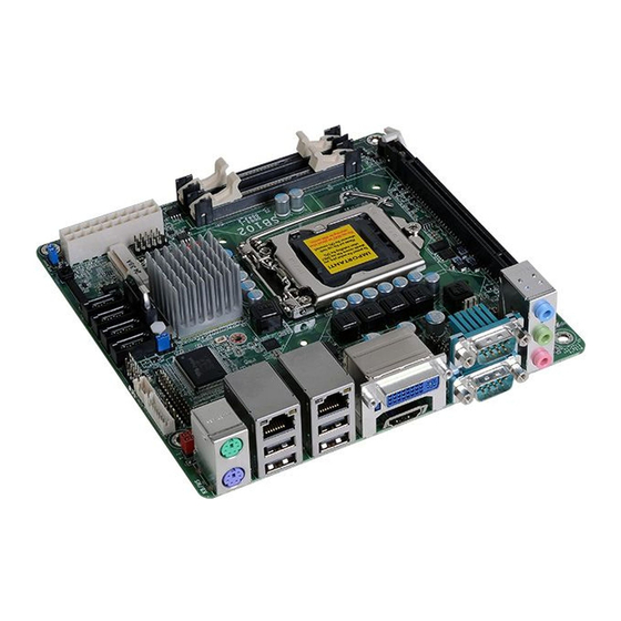
Page 6: Chapter 1 - Introduction
Chapter 1 Chapter 1 - Introduction Specifications Rear Panel I/O • 1 mini-DIN-6 PS/2 mouse port • 1 mini-DIN-6 PS/2 keyboard port Ports • 2 DB-9 serial ports Processor • LGA 1155 socket for: - 1 RS232/422/485 (RS232 and/or Power) - 3rd generation Intel ®... -
Page 7: Features
Chapter 1 • Wake-On-PS/2 Features This function allows you to use the PS/2 keyboard or PS/2 mouse to power-on the system. • Watchdog Timer Important: The Watchdog Timer function allows your application to regularly “clear” the system at the set The 5V_standby power source of your power supply must support ≥720mA. - Page 8 Chapter 1 • ACPI STR The system board is designed to meet the ACPI (Advanced Configuration and Power Interface) specification. ACPI has energy saving features that enables PCs to implement Power Manage- ment and Plug-and-Play with operating systems that support OS Direct Power Management. ACPI when enabled in the Power Management Setup will allow you to use the Suspend to RAM function With the Suspend to RAM function enabled, you can power-off the system at once by pressing...
-
Page 9: Chapter 2 - Hardware Installation
Chapter 2 Chapter 2 - Hardware Installation Important: Board Layout Electrostatic discharge (ESD) can damage your board, processor, disk drives, add-in boards, and other components. Perform installation procedures at an ESD workstation only. If such a station is not available, you can provide some ESD protection by wear- ing an antistatic wrist strap and attaching it to a metal part of the system chassis. -
Page 10: Installing The Dimm Module
Chapter 2 Installing the DIMM Module The system board supports the following memory interface. Single Channel (SC) Note: The system board used in the following illustrations may not resemble the actual Data will be accessed in chunks of 64 bits (8B) from the memory channels. board. -
Page 11: Cpu
Chapter 2 6. Grasping the module by its edges, position the module above the socket with the “notch” in the module aligned with the “key” on the socket. The keying mechanism ensures the module can be plugged into the socket in only one The system board is equipped with a surface mount LGA 1155 socket. -
Page 12: Installing The Cpu
Chapter 2 Load lever Installing the CPU 5. Lifting the load lever will at the same time lift the load plate. 1. Make sure the PC and all other peripheral devices connected to it has been powered down. Lift the load lever up to 2. - Page 13 Chapter 2 7. Insert the CPU into the 8. Close the load plate then socket. The gold triangular push the load lever down. mark on the CPU must align with the corner of While closing the load the CPU socket shown on plate, make sure the front Retention knob edge of the load plate...
-
Page 14: Installing The Fan And Heat Sink
Chapter 2 Installing the Fan and Heat Sink 4. Rotate each push-pin ac- cording to the direction of the arrow shown on top of The CPU must be kept cool by using a CPU fan with heat sink. Without sufficient air circula- the pin. -
Page 15: Jumper Settings
Chapter 2 Jumper Settings PS/2 KB/MS Power Select Clear CMOS Data 1-2 On: +5V 2-3 On: (default) +5V_standby 1-2 On: Normal (default) 2-3 On: Clear CMOS Data JP2 is used to select the power of the PS/2 keyboard and PS/2 mouse ports. Selecting +5V_ standby will allow you to use the PS/2 keyboard or PS/2 mouse to wake up the system. -
Page 16: Usb Power Select
Chapter 2 USB Power Select Power-on Select USB 0-1/8-9 (JP4) 1-2 On: Power-on via power button 1-2 On: +5V 2-3 On: (default) (default) +5V_standby USB 2-3/10-11 2-3 On: (JP7) Power-on via AC power; or Power-on via WOL after G3 1-2 On: +5V 2-3 On: (default) +5V_standby... -
Page 17: Com1 Rs232/422/485 Select
Chapter 2 COM1 RS232/Power Select COM1 RS232/RS422/RS485 Select JP1 (for COM1) is used to configure the COM ports to RS232, RS422 (Full Duplex) or RS485. The pin function of the COM ports will vary according to the jumper’s setting. 3-5 (+5V), 4-6 (+12V) On: 1-3 (RI), 2-4 (DCD) On: RS232 (default) RS232 with power... -
Page 18: Front Audio Or Amplify Select
Chapter 2 Front Audio or Audio Amplify Select 1-3,2-4 On: 3-5,4-6 On: Front audio Audio Amplify (default) JP5 is used to configure front audio or audio amplify select. Chapter 2 Hardware Installation www.dfi .com... -
Page 19: Rear Panel Ports
• PS/2 mouse/keyboard port • 2 LAN ports • 4 USB 2.0 ports • DVI-I port • HDMI port • 2 COM ports • Mic-in jack • Line-in jack • Line-out jack These ports are used to connect a PS/2 mouse and a PS/2 keyboard. The PS/2 mouse port uses IRQ12. Wake-On-PS/2 Keyboard/Mouse The Wake-On-PS/2 Keyboard/Mouse function allows you to use the PS/2 keyboard or PS/2 mouse to power-on the system. To use this function: • Jumper Setting JP2 must be set to “2-3 On: +5V_standby”. Refer to “PS/2 Power Select” in this chapter for more information • BIOS Setting Configure the PS/2 keyboard/mouse wake up function in the Advanced menu (“ACPI Power Management Configuration” submenu) of the BIOS. Refer to chapter 3 for more information. Important: The +5V_standby power source of your power supply must support ≥720mA. Chapter 2 Hardware Installation www.dfi.com... -
Page 20: Rj45 Lan Ports
+Data -Data -Data USB 9 USB 8 USB 2.0 Features USB allows data exchange between your computer and a wide range of simultaneously acces- • Intel 82579LM Gigabit Ethernet Phy sible external Plug and Play peripherals. • Intel 82574L PCI Express Gigabit Ethernet controller The system board is equipped with four onboard USB 2.0/1.1 ports (USB 0-1/ 8-9). The two 10-pin connectors allow you to connect 4 additional USB 2.0/1.1 ports (USB 2-3/ 10-11). The additional USB ports may be mounted on a card-edge bracket. Install the card-edge bracket The LAN ports allow the system board to connect to a local area network by means of a to an available slot at the rear of the system chassis and then insert the USB port cables to a network hub. connector. BIOS Setting BIOS Setting Configure the onboard LAN in the Chipset menu (“South Bridge Configuration” submenu) of Configure the onboard USB in the Advanced menu (“USB Configuration” submenu) of the the BIOS. Refer to chapter 3 for more information. BIOS. Refer to chapter 3 for more information. Driver Installation Driver Installation Install the LAN drivers. Refer to chapter 4 for more information. You may need to install the proper drivers in your operating system to use the USB device. Refer to your operating system’s manual or documentation for more information. Chapter 2 Hardware Installation www.dfi.com... -
Page 21: Graphics Interfaces
Graphics Interfaces Wake-On-USB Keyboard/Mouse The Wake-On-USB Keyboard/Mouse function allows you to use a USB keyboard or USB mouse The display ports consist of the following: to wake up a system from the S3 (STR - Suspend To RAM) state. To use this function: • HDMI port • Jumper Setting • DVI-I port JP6 must be set to “2-3 On: +5V_standby”. Refer to “USB Power Select” in this chapter for more information. DVI-I Important: If you are using the Wake-On-USB Keyboard/Mouse function for 2 USB ports, the +5V_standby power source of your power supply must support ≥1.5A. For 3 or more USB ports, the +5V_standby power source of your power supply must support ≥2A. HDMI HDMI Port The HDMI port which carries both digital audio and video signals is used to connect a LCD monitor or digital TV that has the HDMI port. DVI-I Port The DVI-I port is used to connect an LCD monitor. Connect the display device’s cable connector to the DVI-I port. After you plug the cable con- nector into the port, gently tighten the cable screws to hold the connector in place. BIOS Setting Configure the display device in the Chipset menu (“North Bridge Configuration” submenu) of the BIOS. Refer to chapter 3 for more information. Chapter 2 Hardware Installation www.dfi.com... -
Page 22: Com (Serial) Ports
The pin function of COM 1 port will vary according to JP1’s setting. Refer to “COM1 RS232/ Front audio RS422/RS485 Select” in this chapter for more information. Rear Audio The serial ports are asynchronous communication ports with 16C550A-compatible UARTs that can be used with modems, serial printers, remote display terminals, and other serial devices. The system board is equipped with 3 audio jacks. A jack is a one-hole connecting interface for inserting a plug. Connecting External Serial Ports • Mic-in Jack (Pink) Your COM port may come mounted on a card-edge bracket. Install the card-edge bracket to This jack is used to connect an external microphone. an available slot at the rear of the system chassis then insert the serial port cable to the COM • Line-in Jack (Light Blue) connector. Make sure the colored stripe on the ribbon cable is aligned with pin 1 of the COM This jack is used to connect any audio devices such as Hi-fi set, CD player, tape player, connector. AM/FM radio tuner, synthesizer, etc. BIOS Setting • Line-out Jack (Lime) This jack is used to connect a headphone or external speakers. Configure the serial ports in the Advanced menu (“Super IO Configuration” submenu) of the BIOS. Refer to chapter 3 for more information. Front Audio The front audio connector allows you to connect to the second line-out and mic-in jacks that are at the front panel of your system. Chapter 2 Hardware Installation www.dfi.com... -
Page 23: I/O Connectors
Chapter 2 I/O Connectors BIOS Setting Configure the onboard audio in the Chipset menu (“South Bridge” submenu) of the BIOS. SATA (Serial ATA) Connectors Refer to chapter 3 for more information. Driver Installation Install the audio driver. Refer to chapter 4 for more information. SATA 2.0 3Gb/s Features • 4 Serial ATA ports - 2 SATA2 ports with data transfer rate up to 3Gb/s The Serial ATA connectors are used to connect Serial ATA devices. Connect one end of the Se- rial ATA cable to a SATA connector and the other end to your Serial ATA device. BIOS Setting Configure the Serial ATA drives in the Advanced menu (“SATA Configuration” submenu) of the BIOS. Refer to chapter 3 for more information. Chapter 2 Hardware Installation www.dfi.com... -
Page 24: Digital I/O Connector
Chapter 2 Digital I/O Connector Amplify Connector Digital I/O Power Connector Digital I/O power Digital I/O Out L- Out R+ Amplify Out R- Out L+ The amplify connector which has amplifying feature is used to connect external speakers. Us- ing the same signal cable to connect with external speaker. The 8-bit Digital I/O connector provides powering-on function to external devices that are con- nected to these connectors. Digital I/O Connector Pins Function DIO7 DIO6 DIO5 DIO4 DIO3 DIO2 DIO1 DIO0 Chapter 2 Hardware Installation www.dfi.com... -
Page 25: Chassis Intrusion Connector
Ground Power Sense Signal System_fan 2 Ground Ground Power Sense System_fan 1 Speed Control Sense CPU fan Power Ground The board supports the chassis intrusion detection function. Connect the chassis intrusion sensor cable from the chassis to this connector. When the system’s power is on and a chassis intrusion occurred, an alarm will sound. When the system’s power is off and a chassis intru- The fan connectors are used to connect cooling fans. The cooling fans will provide adequate sion occurred, the alarm will sound only when the system restarts. airflow throughout the chassis to prevent overheating the CPU and system board components. MyGuard Hardware Monitor BIOS Setting Install the “MyGuard Hardware Monitor” utility. By default, the chassis intrusion detection func- The Advanced menu (“PC Health Configuration” submenu) of the BIOS will display the current tion is disabled. When enabled, a warning message will appear when the chassis is open. The speed of the cooling fans. Refer to chapter 3 for more information. utility can also be configured so that a beeping alarm will sound when the chassis is open. Refer to the “MyGuard Hardware Monitor” section in chapter 4 for more information. Chapter 2 Hardware Installation www.dfi.com... -
Page 26: Power Connectors
10 20 +12V Standby Power LED 5VSB PW-OK PS-ON 3.3V -12V Ground 3.3V 3.3V Ground ATX power +12V +12V ATX 12V This LED will lit red when the system is in the standby mode. It indicates that there is power Use a power supply that complies with the ATX12V Power Supply Design Guide Version 1.1. on the system board. Power-off the PC and then unplug the power cord prior to installing any An ATX12V power supply unit has a standard 20-pin ATX main power connector that must be devices. Failure to do so will cause severe damage to the motherboard and components. inserted into the 20-pin connector. The 4-pin +12V power connector enables the delivery of more +12VDC current to the processor’s Voltage Regulator Module (VRM). The power connectors from the power supply unit are designed to fit the 20-pin and 4-pin connectors in only one orientation. Make sure to find the proper orientation before plugging the connectors. The system board requires a minimum of 300 Watt power supply to operate. Your system configuration (CPU power, amount of memory, add-in cards, peripherals, etc.) may exceed the minimum power requirement. To ensure that adequate power is provided, we strongly recom- mend that you use a minimum of 400 Watt (or greater) power supply. Important: Insufficient power supplied to the system may result in instability or the add-in boards and peripherals not functioning properly. Calculating the system’s approximate power usage is important to ensure that the power supply meets the system’s consumption requirements. Chapter 2 Hardware Installation www.dfi.com... -
Page 27: Front Panel Connector
PWR-BTN - Power Switch The Mini PCIe socket is used to install a half size Mini PCIe card. Mini PCIe card is a small form factor PCI card with the same signal protocol, electrical definitions, and configuration This switch is used to power on or off the system. definitions as the conventional PCI. It supports PCIe and USB signals. The Mini PCIe slot does not support mSATA. PWR-LED - Power/Standby LED When the system’s power is on, this LED will light. When the system is in the S1 (POS - Power On Suspend) state, it will blink every second. When the system is in the S3 (STR - Suspend To RAM) state, it will blink every 4 seconds. Pin Pin Assignment Pin Pin Assignment HDD Power LED Power HDD-LED Signal PWR-LED LED Power Ground Signal RESET SW PWR-BTN RST Signal Ground N.C. Signal Chapter 2 Hardware Installation www.dfi.com... -
Page 28: Battery
Pin Assignment Safety Measures Ground DPB_AUXP • Danger of explosion if battery incorrectly replaced. DPB_LANE0_P DPB_AUXN DPB_LANE0_N SDVO_STALLP • Replace only with the same or equivalent type recommend by the manufacturer. Ground SDVO_STALLN • Dispose of used batteries according to local ordinance DPB_LANE1_P SDVO_INTP DPB_LANE1_N SDVO_INTN Ground PCIE_RST DPB_LANE2_P DPB_CTRLCLK DPB_LANE2_N DPB_CTRLDATA Ground DPB_HPD DPB_LANE3_P GPIO15/SMBCLK DPB_LANE3_N GPIO27/SMBDATA/L_BKLTCTL +3V3 +3V3 +12V +12V Chapter 2 Hardware Installation www.dfi.com... -
Page 29: Sdvo-Lvds Daughterboard
Chapter 2 SDVO-LVDS Daughterboard (optional) Power Select for the LCD Panel Features • Chrontel CH7308B • Supports 18/24-bit 1600x1200 LVDS panel (default 1280x1024) • 1 LVDS LCD panel connector 1-2 On: +12V • 1 LCD/Inverter power connector • SDVO interface • Supports dimming control via hot keys or AP tool Dimensions 3-4 On: +5V • 45mm (1.77") x 38mm (1.49") 5-6 On: +3.3V (default) JP8 is used to select the power supplied to the LCD panel. Important: Before powering-on the system, make sure JP8’s setting matches the LCD panel’s specification. Selecting the incorrect voltage will seriously damage the LCD panel. Chapter 2 Hardware Installation www.dfi.com... - Page 30 Function LVDS_Out3+ LVDS_Out7+ LVDS_Out3- LVDS_Out7- LCD/Inverter power LVDS_Out2+ LVDS_Out6+ LVDS_Out2- LVDS_Out6- LVDS_Out1+ LVDS_Out5+ LVDS LCD panel LVDS_Out1- LVDS_Out5- The system board allows you to connect a LCD Display Panel by means of the LVDS LCD panel connector and the LCD/Inverter power connector. These connectors transmit video signals and LVDS_Out0+ LVDS_Out4+ power from the system board to the LCD Display Panel. LVDS_Out0- LVDS_Out4- LVDS_CLK1+ LVDS_CLK2+ LVDS_CLK1- LVDS_CLK2- LVDS_DDCCLK N.C. LVDS_DDCDAA N.C. Panel Power Panel Power Panel Power Panel Power Chapter 2 Hardware Installation www.dfi.com...
- Page 31 Chapter 2 Installing the SDVO-LVDS Daughterboard onto LCD/Inverter Power Connector the Motherboard (optional) Pins Function Important: The motherboard used in this section is for reference purpose only and may not resemble your motherboard. These illustrations are mainly to guide you on how to install SDVO-LVDS onto the motherboard of your choice. Panel Inverter Brightness Voltage Control 1. The photo below shows the location of the mounting hole on the motherboard. Panel Power +3.3V Panel Backlight On/Off Control +12V +12V Mounting hole 2. Insert the provided mounting screw into the mounting hole - from the bottom through the top of the motherboard. Mounting screw Mounting hole Chapter 2 Hardware Installation www.dfi.com...
- Page 32 Chapter 2 3. While supporting the mounting screw at the bottom, from the top side of the board, fasten a bolt into the screw. SDVO connector on the motherboard 5. Press the daughterboard down firmly until it is completely seated on the SDVO connector Bolt of the motherboard. Daughterboard 4. The SDVO connector is located at the bottom of the daughterboard. Grasping the daugh- Motherboard terboard by its edges, position it on top of the motherboard’s SDVO connector with its mounting holes aligned with the bolt on the motherboard. This will also align the SDVO connector of the two boards to each other. SDVO connector at the bottom side of the daughterboard 6. Use the provided mounting screw to secure the daughterboard to the motherboard. Mounting screw Chapter 2 Hardware Installation www.dfi.com...
-
Page 33: Chapter 3 - Bios Setup
Chapter 3 Chapter 3 - BIOS Setup Legends Overview Keys Function The BIOS is a program that takes care of the basic level of communication between the CPU and peripherals. It contains codes for various advanced features found in this system board. Right and Left arrows Moves the highlight left or right to select a menu. -
Page 34: Ami Bios Setup Utility
Chapter 3 AMI BIOS Setup Utility Advanced The Advanced menu allows you to configure your system for basic operation. Some entries are Main defaults required by the system board, while others, if enabled, will improve the performance of your system or let you set some features according to your preference. The Main menu is the first screen that you will see when you enter the BIOS Setup Utility. - Page 35 Chapter 3 ACPI Power Management Configuration PC Health Status This section is used to configure the ACPI Power Management. This section displays the SIO hardware health monitor. Aptio Setup Utility - Copyright (C) 2011 American Megatrends, Inc. Aptio Setup Utility - Copyright (C) 2011 American Megatrends, Inc. Advanced Advanced System Hardware Monitor...
- Page 36 Chapter 3 Boundary 1 to Boundary 4 CPU Configuration The range is from 0-127. This section is used to configure the CPU. It will also display the detected CPU information. Speed Count 1 to Speed Count 5 Aptio Setup Utility - Copyright (C) 2011 American Megatrends, Inc. The range is from 1-100.
- Page 37 Chapter 3 SATA Configuration USB Configuration This section is used to configure SATA functions. This section is used to configure USB. Aptio Setup Utility - Copyright (C) 2011 American Megatrends, Inc. Aptio Setup Utility - Copyright (C) 2011 American Megatrends, Inc. Advanced Advanced SATA Controller(s)
- Page 38 Chapter 3 F71879 Super IO Configuration Serial Port 1 Configuration to Serial Port 2 Configuration This section is used to configure the I/O functions supported by the onboard Super I/O chip. Aptio Setup Utility - Copyright (C) 2011 American Megatrends, Inc. Advanced Aptio Setup Utility - Copyright (C) 2011 American Megatrends, Inc.
-
Page 39: Chipset
Chapter 3 Chipset Network Stack Aptio Setup Utility - Copyright (C) 2011 American Megatrends, Inc. Configures relevant chipset functions. Advanced Network Stack [Enabled] Enable or disable UEFI Aptio Setup Utility - Copyright (C) 2011 American Megatrends, Inc. Ipv4 PXE Support [Enabled] network stack. - Page 40 Chapter 3 South Bridge PCI Express Configuration Aptio Setup Utility - Copyright (C) 2011 American Megatrends, Inc. Aptio Setup Utility - Copyright (C) 2011 American Megatrends, Inc. Chipset Chipset PCI Express Confi guration Control the PCI Express Intel PCH RC Version 1.5.0.0 PCI Express Coniguration Root Port...
- Page 41 Chapter 3 North Bridge USB Configuration Aptio Setup Utility - Copyright (C) 2011 American Megatrends, Inc. Aptio Setup Utility - Copyright (C) 2011 American Megatrends, Inc. Chipset Chipset System Agent Bridge Name IvyBridge Check to enableVT-d USB Confi guration Control the USB EHCI 1.5.0.0 function on MCH.
- Page 42 Chapter 3 Graphics Configuration LCD Control Aptio Setup Utility - Copyright (C) 2011 American Megatrends, Inc. Aptio Setup Utility - Copyright (C) 2011 American Megatrends, Inc. Chipset Chipset LCD Control Select the Video Device Graphics Confi guration Select which of IGFX/ which will be activated IGFX VBIOS Version 2137...
-
Page 43: Boot
Chapter 3 Boot Enabled PEG To enable or disable the PEG. Aptio Setup Utility - Copyright (C) 2011 American Megatrends, Inc. Main Advanced Chipset Boot Security Save & Exit Memory Information Boot Confi guration Number of seconds to Setup Prompt Timeout wait for setup activation Bootup NumLock State [On]... -
Page 44: Security
Chapter 3 Security CSM Parameters Aptio Setup Utility - Copyright (C) 2011 American Megatrends, Inc. Aptio Setup Utility - Copyright (C) 2011 American Megatrends, Inc. Main Advanced Chipset Boot Security Save & Exit Main Advanced Chipset Boot Security Save & Exit This option controls if Launch CSM [Enabled]... -
Page 45: Save & Exit
Chapter 3 Save & Exit Updating the BIOS To update the BIOS, you will need the new BIOS file and a flash utility, AFUDOS. Aptio Setup Utility - Copyright (C) 2011 American Megatrends, Inc. EXE. Please contact technical support or your sales representative for the files. Main Advanced Chipset... -
Page 46: Chapter 4 - Supported Software
Chapter 4 Chapter 4 - Supported Software Auto Run Pages (for Windows 7) The CD that came with the system board contains drivers, utilities and software applications required to enhance the performance of the system board. Insert the CD into a CD-ROM drive. The autorun screen (Mainboard Utility CD) will appear. If after inserting the CD, “Autorun”... - Page 47 Chapter 4 Microsoft .NET Framework 3.5 3. Click Exit. (for Windows XP only) Note: Before installing Microsoft .NET Framework 3.5, make sure you have updated your Windows XP operating system to Service Pack 3. To install the driver, click “Microsoft .NET Framework 3.5” on the main menu. 1.
-
Page 48: Intel Chipset Software Installation Utility
Chapter 4 Intel Chipset Software Installation Utility 3. Go through the readme document for more installa- tion tips then click Next. The Intel Chipset Software Installation Utility is used for updating Windows INF files so that ® the Intel chipset can be recognized and configured properly in the system. To install the utility, click “Intel Chipset Software Installation Utility”... -
Page 49: Intel Graphics Drivers
Chapter 4 Microsoft DirectX 9.0C (for Windows XP only) Intel Graphics Drivers To install the driver, click “Microsoft DirectX 9.0C” on the main menu. To install the driver, click “Intel Graphics Drivers” on the main menu. 1. Setup is now ready to 1. -
Page 50: Audio Drivers
Chapter 4 Audio Drivers 3. Go through the readme document for system re- quirements and installation To install the driver, click “Audio Drivers” on the main menu. tips then click Next. 1. Setup is ready to install the driver. Click Next. 4. -
Page 51: Intel Lan Drivers
Chapter 4 Intel LAN Drivers 4. Click Install to begin the installation. To install the driver, click “Intel LAN Drivers” on the main menu. 1. Setup is ready to install the driver. Click Next. 5. After completing installa- tion, click Finish. 2. -
Page 52: Intel Management Engine Drivers
Chapter 4 Intel Management Engine Drivers 3. Setup is currently installing the driver. After installation has completed, click Next. To install the driver, click “Intel Management Engine Drivers” on the main menu. 1. Setup is ready to install the driver. Click Next. 4. -
Page 53: Myguard Hardware Monitor
Chapter 4 6. Click Install to begin instal- MyGuard Hardware Monitor lation. 1. Locate for the MyGuard folder in the provided disc. 2. In the MyGuard folder, right-click on the “setup” file. 3. Select Run As Administrator. 4. Double-click Setup. 7. -
Page 54: Dfi Utility
Chapter 4 DFI Utility 3. Enter “User name” (SB102) and “Organization” information DFI Utility provides information about the board, Watchdog, DIO, and Backlight. then click “Next”. To access the utility, click “DFI Utility” on the main menu. Note: If you are using Windows 7, you need to access the operating system as an administrator to be able to install the utility. - Page 55 Chapter 4 Adobe Acrobat Reader 9.3 The DFI Utility icon will appear on the desktop. Double-click the icon to open the utility. To install the reader, click “Adobe Acrobat Reader 9.3” on the main menu. 1. Click Next to install or click Change Destination Folder to select another folder.
-
Page 56: Appendix A - Watchdog Sample Code
Appendix A Appendix A - Watchdog Sample Code ;Software programming example: ;--------------------------------------------- ;(1) Enter Super IO Confi guration mode ;--------------------------------------------- DX,2EH AL,87H DX,AL DX,AL ;------------------------------------------------------------------------------------------- ;(2) Confi guration Logical Device 7, register CRF5/CRF6 (WDT Control /WDT timer) ;------------------------------------------------------------------------------------------- DX,2EH AL,07H ;Ready to Program Logical Device DX,AL DX,2FH... -
Page 57: Appendix B - System Error Message
Appendix B Appendix B - System Error Message Hard Disk(s) fail (20) When the BIOS encounters an error that requires the user to correct something, either a beep HDD initialization error. code will sound or a message will be displayed in a box in the middle of the screen and the message, PRESS F1 TO CONTINUE, CTRL-ALT-ESC or DEL TO ENTER SETUP, will be shown in Hard Disk(s) fail (10) the information box at the bottom. -
Page 58: Appendix C - Troubleshooting
Appendix C Appendix C - Troubleshooting Checklist The picture seems to be constantly moving. Troubleshooting Checklist 1. The monitor has lost its vertical sync. Adjust the monitor’s vertical sync. 2. Move away any objects, such as another monitor or fan, that may be creating a magnetic This chapter of the manual is designed to help you with problems that you may encounter field around the display. -
Page 59: Hard Drive
Appendix C Hard Drive System Board 1. Make sure the add-in card is seated securely in the expansion slot. If the add-in card is Hard disk failure. loose, power off the system, re-install the card and power up the system. 1.
Need help?
Do you have a question about the SB102-D and is the answer not in the manual?
Questions and answers