Advertisement
Quick Links
INSTALLATION INSTRUCTIONS
SL2 SERIES CHIME AND CHIME-STROBE
WITH PRE-WIRE/PRE-TEST (CEILING MOUNT)
IMPORTANT: All audible and visual signaling appliances must be installed in accordance with all applicable national and local fire alarm
codes and any other required regulatory agencies.
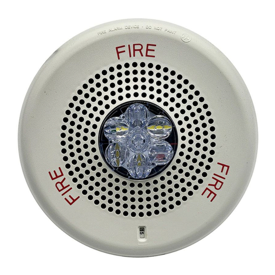
The Siemens SL2CHC Chime and SL2CHSC Chime-Strobe appliances are designed for easy installation with a pre-wire capable mounting
plate. All models are for 24V operation. Series SL2CHC/SL2CHSC Chime is UL Listed for indoor fire protection service under Standard
UL464 for Private Mode Audible Signal Appliances as well as ULC-S525-2016 (Audible Signaling Devices for Fire Alarm and Signaling
Systems). The SL2 Chime is designed for low current draw and versatile performance. The SL2 Chime offers a choice of 1Hz, 2Hz, coded,
or temporal code 3 (T3) operation. It has an adjustable sound level, and operates at a frequency of 890Hz. The Low Profile design
incorporates a high efficiency speaker for maximum output at minimum power, and features a sealed back construction for extra protection
and improved audibility. These models are listed for indoor use and ceiling mount with the backboxes specified in these instructions (see
mounting options). Model SL2CHC (non-strobe) may be wall or ceiling mounted.
The Siemens SL2 strobe meets NFPA 2016 20 millisecond light pulse duration code requirements. In addition, the Siemens SL2 product
line has been UL/ULC listed as compatible with all Fire Alarm Control Panels (FACP) and accessories that have been determined to be
compatible with Siemens ST Strobe based products including the SL, ST, SE, SEH, SET, S-HQ, STH, AS, CH, HS, MTH and Z series. The
maximum number of SL2 devices per NAC is determined by dividing the maximum current rating of the FACP NAC by the total current
rating of one SL2 device, with a maximum of 105 SL2 devices per NAC. Refer to FACP installation instructions and relevant compatibility
guides for more detail. The Siemens SL2 Series may be installed in the same notification zone and field of view with any Siemens ST, SL,
and Z series Strobe based product.
Siemens SL2 Multi-Candela Chime-Strobes can provide a synchronized strobe appliance when used in conjunction with an FACP that
incorporates the Siemens sync protocol, a Sync Module (DSC), or the Siemens Power Supply.
CAUTION: Do not change factory applied finishes. "DO NOT PAINT".
ATTENTION: Ne pas modifiez les finitions appliquées en usine. "NE PAS PEINTURER"
IMPORTANT: PLEASE READ THESE INSTRUCTIONS CAREFULLY. FAILURE TO COMPLY WITH ANY OF THE FOLLOWING
INSTRUCTIONS COULD RESULT IN IMPROPER APPLICATION, INSTALLATION AND/OR OPERATION OF THESE PRODUCTS IN
AN EMERGENCY SITUATION, WHICH COULD RESULT IN PROPERTY DAMAGE AND SERIOUS INJURY OR DEATH TO YOU
AND/OR OTHERS.
SPECIFICATIONS:
Models
SL2CHC (Chime), SL2CHSC (Chime-Strobe)
Agency
Strobe: UL1638, UL1971,CAN/ULC-S526-16
Sounder: UL464, CAN/ULC-S525-16
Input Voltage
DC or FWR, 24V Regulated, 16 to 33V (All models)
Chime Patterns
1Hz, 2Hz, Coded, T3 (field selectable, Table 4)
Strobe Light Output
Strobe: 15, 30, 75, 110, 150, 177cd (field selectable)
NAC Characteristics
Max. line resistance: 35Ω
Environmental
Indoor Use Only. 0° C - 50° C (32° F - 122° F) 93% R.H.
Table 2A: SL2CH Chime – Current and Sound Pressure Level Ratings
Maximum
RMS
Current
UL/ULC Voltage
(Amps)
DC
16.0 – 33.0 Vdc
0.022
FWR
16.0 – 33.0 Vrms
0.022
Table 2B: Directional Characteristics
-3dB
+/- 90 Degrees Horizontal, +/- 90 Degrees Vertical (does not reach 3dB)
-6dB
+/- 90 Degrees Horizontal, +/- 90 Degrees Vertical (does not reach 6dB)
Table 3: SL2CHSC Strobe Current Ratings (AMPS) **
Regulated 24DC (16-33VDC)
Candela Setting
15cd
DC
0.022
FWR
0.036
** Setting will determine the current draw of the product.
PN P85865-001A
Table 1: Specifications
Reverberant dBA at 10Ft
Anechoic dBA at 10 Ft
per UL464
per CAN/ULC-S525-16
for Private Mode
for Dwelling Use Only
Min
Max
Min
51
68
61
51
68
61
Regulated 24FWR (16-33VRMS)
30cd
75cd
110cd
150cd
0.030
0.060
0.086
0.125
0.050
0.092
0.142
0.196
When calculating the total currents: Use Table 2A and Table 3 to determine the highest value of "RMS Current" for an individual appliance,
then multiply these values by the total number of appliances; be sure to add the currents for any other appliances powered by the same
source and include any required safety factors.
Make sure that the total RMS current required required by all appliances that are connected to the system's PRIMARY and SECONDARY
power sources, NAC circuits, DSC Sync Modules or Siemens Power Supplies does not exceed the power sources' rated capacity or the
current ratings of any fuses on the circuits to which these appliances are wired.
Check the minimum and maximum output of the power supply and standby battery, and subtract the voltage drop from the circuit wiring
resistance to determine the applied voltage to the appliance.
WIRING DIAGRAMS:
Figure 1B: One circuit.
SL2CHS Chime and Strobe activate in unison.
+
FROM PRECEDING APPLIANCE
FACP, POWER SUPPLY
-
OR SYNC MODULE
*Refer to DC Sync Module instruction sheets or Siemens Power Supplies for additional information.
Figure 2:
NOTES:
Max
1.
The strobe will produce 1 flash per second over the "Regulated Voltage" range.
78
2.
Strobe is not designed to be used on coded systems in which the applied voltage is cycled on and off.
78
3.
The maximum number of SL2 strobes on a single notification appliance circuit shall not exceed 105.
4.
These appliances are UL Listed as "Regulated". They are intended to be used with FACPs whose notification circuits are UL Listed
as "Regulated."
5.
These appliances were tested to the regulated voltage limits of 16.0-33.0 Volts. Do not apply voltage outside of this range. Check
the minimum and maximum output of the power supply and standby battery and subtract the voltage drop from the circuit wiring
resistance to determine the applied voltage to the strobes. The max wire impedance between strobes shall not exceed 35 ohms.
6.
Make sure that the total RMS current required by all appliances that are connected to the system's primary and secondary power
sources, notification appliance circuits, sync modules, or power supplies does not exceed the power sources rated capacity or the
current ratings of any fuses on the circuits to which these appliances are wired.
177cd
7.
The Code 3 temporal pattern (1/2 second on, 1/2 second off, 1/2 second on, 1/2 second off, 1/2 second on, 1-1/2 off and repeat) is
0.185
specified by ANSI and NFPA 72 for standard emergency evacuation signaling. Code 3 shall be used only for fire evacuation signaling
0.274
and not for any other purpose.
8.
The effect of shipping and storage temperatures shall not adversely affect the performance of the appliance when it is stored in the
original cartons and not subjected to misuse or abuse.
Siemens Industry, Inc.
Building Technologies Division
2 Gatehall Drive
Parsippany, NJ 07054
PN P85865-001A
Figure 1A: One Circuit. SL2CH Chime
+
FROM PRECEDING APPLIANCE
FACP, POWER SUPPLY
-
OR SYNC MODULE
-
+
Figure 1C: Two Circuits (Chime may be Coded)
SL2CHS Chime and Strobe will operate independently
-
+
+
FROM PRECEDING APPLIANCE
FACP, POWER SUPPLY
OR SYNC MODULE
+
TO NEXT
FROM PRECEDING APPLIANCE
APPLIANCE
FACP, POWER SUPPLY
-
OR E.O.L.R.
OR SYNC MODULE
-
+
+
1. This model has in-out wiring terminals that accept two #12 to #18 American Wire Gauge (AWG) wires at
each screw terminal. Strip leads 3/8 inches and connect to screw terminals.
2. Break all in-out wire runs on supervised circuits to assure integrity of circuit supervision as shown in
Figure 2. The polarity shown in the wiring diagrams is for operation of the appliances. The polarity is
reversed by the FACP during supervision.
Siemens Canada Limited
Building Technologies Division
1577 North Service Road East
Oakville, Ontario, L6H 0H6
Canada
+
TO NEXT
APPLIANCE
-
OR E.O.L.R.
+
-
+
+
+
+
TO NEXT
APPLIANCE
-
-
OR E.O.L.R.
+
+
TO NEXT
APPLIANCE
-
-
OR E.O.L.R.
-
+
+
Page 1
Advertisement

Related Manuals for Siemens SL2CHC


Summary of Contents for Siemens SL2CHC
- Page 1 SL2 device, with a maximum of 105 SL2 devices per NAC. Refer to FACP installation instructions and relevant compatibility guides for more detail. The Siemens SL2 Series may be installed in the same notification zone and field of view with any Siemens ST, SL, and Z series Strobe based product.
- Page 2 Strobe device has only one mounting orientation. LED light element should be oriented toward the floor Align cover to the SL2CHC/SL2CHSC appliance with strobe opening over LED lens. Then, snap the cover in place. To remove the appliance, insert a small flat-bladed screwdriver into the opening ½” as shown in Figure 5. Then remove the grille.
Need help?
Do you have a question about the SL2CHC and is the answer not in the manual?
Questions and answers