
Related Manuals for Siemens FDM275-O


Summary of Contents for Siemens FDM275-O
- Page 1 FDM275-O Radio manual call point Technical Manual Building Technologies A6V10425652_en--_f 2016-11-28 Control Products and Systems...
- Page 2 Issued by: Siemens Switzerland Ltd. Building Technologies Division International Headquarters Gubelstrasse 22 CH-6301 Zug Tel. +41 41 724-2424 www.siemens.com/buildingtechnologies Edition: 2016-11-28 Document ID: A6V10425652_en--_f © Siemens Switzerland Ltd, 2014 2 | 46 Building Technologies A6V10425652_en--_f Fire Safety 2016-11-28...
-
Page 3: Table Of Contents
Table of contents About this document ................5 Applicable documents ................. 7 Download center ..................8 Technical terms and abbreviations .............. 8 Revision history ..................9 Safety ....................10 Safety instructions ..................10 Safety regulations for the method of operation ...........12 Standards and directives complied with............14 Release Notes ...................14 Structure and function ................. - Page 4 Fields of application ................... 24 Mounting site ..................... 24 Environmental influences ................24 Mounting and installation ..............25 Mounting radio manual call point FDM275-O..........25 Installation ....................26 Replacing the plastic insert with a glass insert..........29 Installing the protective cover ..............30 Commissioning ...................31...
-
Page 5: About This Document
Intended use The radio manual call point FDM275-O may only be used in a fire detection system with a radio gateway approved by the manufacturer. The radio manual call point FDM275-O is compatible with the radio module FDRF272-O. - Page 6 About this document Applicable documents Document identification The document ID is structured as follows: A6Vxxxxxxxx_aaAA_vv A6Vxxxxxxxx_--AA_vv A6Vxxxxxxxx_aa--_vv A6Vxxxxxxxx_----_vv ID code Description A6Vxxxxxxxx STEP-ID generated by the STEP system Separator Language abbreviation in accordance with ISO 639-1 Country abbreviation in accordance with ISO-3166-1 Multilingual or international Document version, single or double digit: a, b, …z;...
-
Page 7: Applicable Documents
A6V10431682 Data sheet Radio fire detection system OEM A6V10367669 Open-Source Software (OSS) Licenses A6V10425655 Installation Radio manual call point FDM275-O Applicable documents also include your installation manufacturer's technical manual and your radio gateway manufacturer's technical manual. 7 | 46 A6V10425652_en--_f... -
Page 8: Download Center
You can download various types of documents, such as data sheets, installation instructions, and license texts via the following Internet address: http://siemens.com/bt/download Enter the document ID in the 'Find by keyword' input box. You will also find information about search variants and links to mobile applications (apps) for various systems on the home page. -
Page 9: Revision History
About this document Revision history 1.4 Revision history The reference document's version applies to all languages into which the reference document is translated. The first edition of a language version or a country variant may, for example, be version 'd' instead of 'a' if the reference document is already this version. The table below shows this document's revision history: Modification index Edition date... -
Page 10: Safety
Safety Safety instructions 2 Safety 2.1 Safety instructions The safety notices must be observed in order to protect people and property. The safety notices in this document contain the following elements: Symbol for danger Signal word Nature and origin of the danger Consequences if the danger occurs Measures or prohibitions for danger avoidance Symbol for danger... - Page 11 Safety Safety instructions How risk of injury is presented Information about the risk of injury is shown as follows: WARNING Nature and origin of the danger Consequences if the danger occurs Measures / prohibitions for danger avoidance How possible damage to property is presented Information about possible damage to property is shown as follows: NOTICE Nature and origin of the danger...
-
Page 12: Safety Regulations For The Method Of Operation
2.2 Safety regulations for the method of operation National standards, regulations and legislation Siemens products are developed and produced in compliance with the relevant European and international safety standards. Should additional national or local safety standards or legislation concerning the planning, mounting, installation,... - Page 13 Disregard of the safety regulations Before they are delivered, Siemens products are tested to ensure they function correctly when used properly. Siemens disclaims all liability for damage or injuries caused by the incorrect application of the instructions or the disregard of danger warnings contained in the documentation.
-
Page 14: Standards And Directives Complied With
Safety Standards and directives complied with 2.3 Standards and directives complied with A list of the standards and directives complied with is available from your Siemens contact. 2.4 Release Notes Limitations to the configuration or use of devices in a fire detection installation with a particular firmware version are possible. -
Page 15: Structure And Function
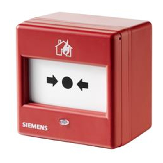
3 Structure and function 3.1 Overview The manual call point FDM275-O is intended for use in areas of a building where a fire can be detected by people who can manually trigger an alarm. The manual call point FDM275-O consists of a back box, a switching unit, and a battery pack. -
Page 16: Details For Ordering
Plastic insert 'Neutral' FDMK295 A5Q00013448 3.1.2 Scope of delivery The radio manual call point FDM275-O is supplied with a mounted plastic insert 'Neutral' FDMG295 and key FDMK295, and without a battery pack. The following items must be ordered separately: Battery pack BAT3.6-10 Glass insert 'Neutral' 3.1.3 Product version ES... -
Page 17: Power Supply
Structure and function Overview Product version on the product label and the type plate Details of the product version can be found after the device order number: Figure 2: Example of a product label with details of the product version Depending on the product and various approvals, the product labels may differ in terms of the information type and layout. -
Page 18: Setup
Structure and function Setup 3.2 Setup 180° Figure 4: Radio manual call point FDM275-O 1 Back box 8 Plastic/glass insert 2 Screws for wall mounting 9 Pressure point marking 3 Battery connector 10 Housing cover 4 Battery pack BAT3.6-10 11 Key... -
Page 19: Function
3.3.2 Internal alarm indicator The internal alarm indicator's LED has two colors and shows the operating condition of the radio manual call point FDM275-O. Figure 5: Internal alarm indicator The table below describes the flashing behavior of the internal alarm indicator in the radio manual call point FDM275-O: Several flashing patterns are available for normal operation. - Page 20 Structure and function Function Operating condition Flashing Graphic mode Alarm IAI flashes red once a second Alarm in test mode IAI flashes green twice every four seconds and red every second in- between Fault There is an error. IAI flashes red four times every second Commissioning...
-
Page 21: Test Mode
Structure and function Function Operating condition Flashing Graphic mode New battery IAI lights up once for five seconds Battery is flat IAI off Several operating conditions may be indicated at the same time. This may lead to the flashing patterns overlapping one another. The red LED indicator has priority over the green LED indicator. -
Page 22: Accessories
Inscription field for commissioning date Compatible with: – Radio manual call point FDM273-O – Radio manual call point FDM275-O – Radio fire detector FDOOT271-O Order number: S54370-Z11-A1 3.4.2 Key FDMK295 For testing and resetting manual call points For removing the housing cover from the back Compatible with: –... -
Page 23: Plastic Insert Fdmp295
Structure and function Accessories 3.4.4 Plastic insert FDMP295 For alarm activation and protection against soiling Compatible with: – Radio manual call point FDM275-O Order number: A5Q00013445 3.4.5 Protective cover FDMC295 For protection against unintended alarm activation Compatible with: – Radio manual call point FDM275-O... -
Page 24: Planning
Planning Fields of application 4 Planning 4.1 Fields of application The radio manual call points are intended for use in places where a fire can be detected by people who can manually trigger an alarm. 4.2 Mounting site The radio manual call points must be mounted in easily accessible places at a height of 0.9...1.6 m on an even surface. -
Page 25: Mounting And Installation
Mounting radio manual call point FDM275-O 5 Mounting and installation 5.1 Mounting radio manual call point FDM275-O Secure the radio manual call point FDM275-O at a height of 0.9…1.6 m on an even surface. Observe the country-specific regulations for the exact mounting height! Figure 6: Opening the housing with the key FDMK295 w The position of radio manual call point FDM275-O has been established. -
Page 26: Installation
Mounting and installation Installation 5.2 Installation 180° 1 Back box 9 Screws for switching unit 2 Battery pack BAT3.6-10 10 Internal alarm indicator 3 Type plate with adhesive label 11 Plastic/glass insert 4 Battery holders 12 Housing cover 5 Battery connector 13 Retainer 6 Housing switching contact 14 Spring... - Page 27 The internal alarm indicator flashes red. a The radio manual call point FDM275-O is set to the factory setting. 4. Insert the battery pack into the switching unit so that it snaps into place in the three battery holders (4).
- Page 28 Mounting and installation Installation OUT OF ORDER AUSSER BETRIEB HORS SERVICE FUORI SERVIZIO FUERA DE SERVICIO BUITEN GEBRUIK A5Q00030603 Figure 7: 'Not in use' label See also 2 Internal alarm indicator [ 28 | 46 Building Technologies A6V10425652_en--_f Fire Safety 2016-11-28...
-
Page 29: Replacing The Plastic Insert With A Glass Insert
5.3 Replacing the plastic insert with a glass insert Proceed as follows to replace the plastic insert with a glass insert: w The gateway detector line to which the radio manual call point FDM275-O is logged on is switched off. -
Page 30: Installing The Protective Cover
(1) intended for this purpose. See also 'Protective cover FDMC295' chapter. a The protective cover is installed. Figure 9: Installing the protective cover FDMC295 1 Radio manual call point FDM275-O 2 Protective cover 30 | 46 Building Technologies... -
Page 31: Commissioning
Commissioning Performance check 6 Commissioning When the battery connector is connected, the radio manual call point FDM275-O is activated. Insert the battery packs into the devices at the location where they are going to be used just before commissioning the fire detection installation. -
Page 32: Localization And Device Testing
Commissioning Localization and device testing 6.2 Localization and device testing The manual call points have an internal alarm indicator [ 19]. This internal alarm indicator may also be activated from the control panel for localization and device testing. The table shows the LED indication for the different control panel commands. -
Page 33: Maintenance / Repair
2. Pull the key out of the housing and push the plastic insert upward. a The internal alarm indicator stops flashing. a The radio manual call point FDM275-O is ready for operation. Figure 11: Establishing the state of operational readiness of the radio manual call point with plastic... - Page 34 Snap the bottom housing cover into place in the back box. 5. If necessary, check the function of the manual call point. See the chapter 'Performance check'. a The radio manual call point FDM275-O is ready for operation. Figure 12: Replacing the glass insert Broken glass insert...
-
Page 35: Establishing Factory Settings
7.2 Establishing factory settings All existing settings are deleted and reset to the factory settings. The radio manual call point FDM275-O can only be integrated into a radio cell as a new device if it is set to its factory settings. - Page 36 5. Press the button in the 'new' opening (3) with a slim pen or pencil (4) for approx. five seconds. a The internal alarm indicator flashes red every 2 seconds. a The radio manual call point FDM275-O is set to the factory setting (Installation 26]). 36 | 46...
-
Page 37: Basic Principles For Replacing The Battery Pack
Maintenance / Repair Basic principles for replacing the battery pack 7.3 Basic principles for replacing the battery pack WARNING Risk of explosion due to fire or short-circuit, even if the battery pack is discharged Injuries caused by flying parts To prevent the connection wires short-circuiting, insulate the connections and stick the battery cable to the battery pack. -
Page 38: Replacing The Battery Pack In The Radio Manual Call Point
Maintenance / Repair Replacing the battery pack in the radio manual call point 7.4 Replacing the battery pack in the radio manual call point NOTICE Unintentional alarm activation Removing the glass or plastic insert triggers an alarm if the detector line is activated. - Page 39 8. Connect the battery connector (8). a The alarm indicator lights up red for 5 seconds. a After a further 10 seconds, the radio manual call point FDM275-O signals that it is no longer installed in the housing and the alarm indicator flashes green (flashing pattern number 3 with interval of 2 seconds).
-
Page 40: Specifications
Specifications Technical data 8 Specifications 8.1 Technical data You will find information on approvals, CE marking, and the relevant EU directives for this device (these devices) in the following document(s); see 'Applicable documents' chapter: Document A6V10431682 Device characteristics Detector diagnosis With Wireless diagnostic tool or connected fire control panel Type of alarm activation... - Page 41 Specifications Technical data Ambient conditions Place of installation Inside buildings/indoors Operating temperature -10…+55 °C Storage temperature -30…+75 °C Air humidity 95 % rel. Protection categories (IEC 60529): IP24D Electromagnetic compatibility: 10 kHz…100 kHz 160 V/m 100 kHz…2.5 GHz 30 V/m Mechanical data Weight: 0.216 kg...
-
Page 42: Dimensions
Specifications Dimensions 8.2 Dimensions 86.8 36.5 8.3 Master gauge for recesses 25.4 25.4 A, B = 5.3 mm 42 | 46 Building Technologies A6V10425652_en--_f Fire Safety 2016-11-28... -
Page 43: Environmental Compatibility And Disposal
Specifications Environmental compatibility and disposal 8.4 Environmental compatibility and disposal This equipment is manufactured using materials and procedures which comply with current environmental protection standards as best as possible. More specifically, the following measures have been undertaken: Use of reusable materials Use of halogen-free plastics Electronic parts and synthetic materials can be separated Larger plastic parts are labeled according to ISO 11469 and ISO 1043. -
Page 44: Glossary
Glossary Glossary Factory setting Basic settings present at the time of delivery Radio device Any device that the radio gateway monitors 44 | 46 Building Technologies A6V10425652_en--_f Fire Safety 2016-11-28... -
Page 45: Index
Index Index Flashing mode Application area Internal alarm indicator ........19 Ambient conditions.......... 24 Flashing pattern Approvals ............40 Configuration ..........19 Internal alarm indicator ........19 Battery pack Description............22 Impact Replacing ............38 Chemicals ............24 Replacing the battery pack ......37 Moisture ............ - Page 46 Issued by © Siemens Switzerland Ltd, 2014 Siemens Switzerland Ltd Technical specifications and availability subject to change without notice. Building Technologies Division International Headquarters Gubelstrasse 22 CH-6301 Zug +41 41-724 24 24 www.siemens.com/buildingtechnologies Document ID: A6V10425652_en--_f Edition: 2016-11-28...
Need help?
Do you have a question about the FDM275-O and is the answer not in the manual?
Questions and answers