Advertisement
Quick Links
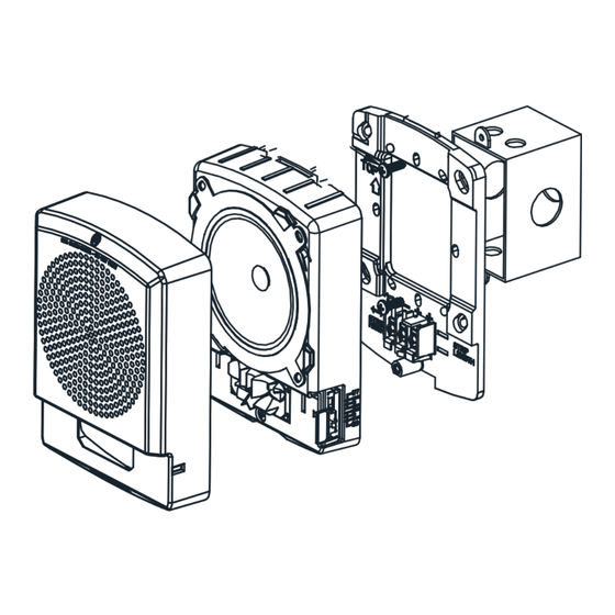
INSTALLATION INSTRUCTIONS
SL2 LOW FREQUENCY SOUNDER STROBES AND SOUNDERS
WITH PRE-WIRE/PRE-TEST (WALL MOUNT)
IMPORTANT: All audible and visual signaling appliances must be installed in accordance with all applicable national and local fire alarm
codes and any other required regulatory agencies.
The Siemens SL2FS Sounder (520Hz) and SL2FSS Sounder Strobe (110/177cd) appliances are designed for easy installation with a pre-
wire capable mounting plate. All models are for 24V operation. The SL2FS Sounder and SL2FSS Sounder Strobe are rated as low
frequency devices per UL 464, suitable for sleeping areas per NFPA 72. The SL2FS sounder may be wall or ceiling mounted.
The Siemens SL2 strobe meets NFPA 2016 20 millisecond light pulse duration code requirements. In addition, the Siemens SL2 product
line has been UL/ULC listed as compatible with all Fire Alarm Control Panels (FACP) and accessories that have been determined to be
compatible with Siemens ST Strobe based products including the SL, ST, SE, SEH, SET, S-HQ, STH, AS, CH, HS, MTH and Z series. The
maximum number of SL2 devices per NAC is determined by dividing the maximum current rating of the FACP NAC by the total current
rating of one SL2 device, with a maximum of 105 SL2 devices per NAC. Refer to FACP installation instructions and relevant compatibility
guides for more detail. The Siemens SL2 Series may be installed in the same notification zone and field of view with any Siemens ST, SL,
and Z series Strobe based product.
Siemens Low Frequency Sounder Strobe can provide a synchronized strobe appliance when used in conjunction with an FACP that
incorporates the Siemens Sync Protocol, a DSC Sync Module or a Siemens Power Supply. When set to the T3/4 setting, a DSC Sync
Module can toggle the Low Frequency Sounder between Code 3 (T3) for fire/emergency evacuation and Code 4 (T4) for carbon monoxide
(CO).
CAUTION: Do not change factory applied finishes. "DO NOT PAINT".
ATTENTION: Ne pas modifiez les finitions appliquées en usine. "NE PAS PEINTURER"
IMPORTANT: PLEASE READ THESE INSTRUCTIONS CAREFULLY. FAILURE TO COMPLY WITH ANY OF THE FOLLOWING
INSTRUCTIONS COULD RESULT IN IMPROPER APPLICATION, INSTALLATION AND/OR OPERATION OF THESE PRODUCTS IN
AN EMERGENCY SITUATION, WHICH COULD RESULT IN PROPERTY DAMAGE AND SERIOUS INJURY OR DEATH TO YOU
AND/OR OTHERS.
SPECIFICATIONS:
Models
SL2FSS (Sounder Strobe), SL2FS (Sounder)
Agency
Strobe: UL1638, UL1971,CAN/ULC-S526-16
Sounder: UL464, CAN/ULC-S525-16
Input Voltage
DC or FWR, 24V Regulated, 16 to 33V (All models)
Non-Sync: Continuous, Code 3 (field selectable)
Sounder Patterns
Siemens Sync Protocol: Code 3 Sync, T3/T4 Sync Selectable (with DSC)
Coded Operation: Use Continuous Setting on SL2FS Sounder Only Model
Strobe Light Output
110cd or 177cd (field selectable)
NAC Characteristics
Max. line resistance: 35Ω
Environmental
Indoor Use Only. 0° C - 50° C (32° F - 122° F) 93% R.H.
* Code 3/Code 4 (T3/T4) operation requires the use of the Siemens Sync Protocol or DSC module.
Table 2: Current Ratings (AMPS) **
Regulated 24DC (16-33VDC)
Sound Setting
SL2FSS
110cd
Continuous (CONT)
0.164
Code 3 (T3)
0.164
Code 3/Code 4 (T3/4)
0.164
** Setting will determine the current draw of the product.
When calculating the total currents use Table 2 to determine the highest value of RMS current for an individual appliance, then multiply
these values by the total number of appliances. Be sure to add the currents for any other appliances, including audible signaling
appliances powered by the same source, and to include any required safety factors.
Important: When installing strobes in an open office or other areas containing partitions or other viewing obstructions, special attention
should be given to the location of the strobes so that the operating effect can be seen by all intended viewers. Furthermore, the intensity,
number, and type of strobes shall be sufficient to alert the intended viewer with proper illumination, regardless of the viewers orientation.
A small possibility exists that the use of multiple strobes within a person's field of view, may induce a photo-sensitive response in persons
with epilepsy. Strobe reflections in a glass or mirrored surface might also induce such a response. To minimize this possible hazard,
Siemens strongly recommends that the strobes installed should not present a composite flash rate in the field of view which exceeds five
(5) Hz at the operating voltage of the strobes. Siemens also strongly recommends that the intensity and composite flash rate of installed
strobes comply with levels established by applicable laws, standards, regulations, codes and guidelines.
PN P85753-001A
Table 1: Specifications
Regulated 24FWR (16-33VRMS)
SL2FSS
SL2FS
SL2FSS
SL2FSS
177cd
110cd
177cdr
0.256
0.098
0.235
0.348
0.256
0.098
0.235
0.348
0.256
0.098
0.235
0.348
Sound Setting
Continuous
Code 3
Code 3/Code 4
WIRING DIAGRAMS:
FROM PRECEDING APPLIANCE
*Refer to DSC Sync Module instruction sheet or Siemens Power Supplies for additional information.
Figure 2:
NOTES:
1.
The strobe will produce 1 flash per second over the "Regulated Voltage" range.
SL2FS
2.
Strobe are not designed to be used on coded systems in which the applied voltage is cycled on and off.
3.
The maximum number of SL2 strobes on a single notification appliance circuit shall not exceed 105.
0.138
4.
These appliances are UL Listed as "Regulated". They are intended to be used with FACPs whose notification circuits are UL Listed
0.138
as "Regulated."
5.
These appliances were tested to the regulated voltage limits of 16.0-33.0 Volts. Do not apply voltage outside of this range. Check
0.138
the minimum and maximum output of the power supply and standby battery and subtract the voltage drop from the circuit wiring
resistance to determine the applied voltage to the strobes. The max wire impedance between strobes shall not exceed 35 ohms.
6.
Make sure that the total RMS current required by all appliances that are connected to the system's primary and secondary power
sources, notification appliance circuits, sync modules, or power supplies does not exceed the power sources rated capacity or the
current ratings of any fuses on the circuits to which these appliances are wired.
7.
The Code 3 temporal pattern (1/2 second on, 1/2 second off, 1/2 second on, 1/2 second off, 1/2 second on, 1-1/2 off and repeat) is
specified by ANSI and NFPA 72 for standard emergency evacuation signaling. Code 3 Horn shall be used only for fire evacuation
signaling and not for any other purpose.
8.
The Code 4 temporal pattern (100 ms on, followed by 100 ms off, for 4 cycles, followed by 5 seconds of silence and repeat), is specified
by ANSI and NFPA 720 for carbon monoxide emergency signaling.
9.
The effect of shipping and storage temperatures shall not adversely affect the performance of the appliance when it is stored in the
original cartons and not subjected to misuse or abuse.
Siemens Industry, Inc.
Building Technologies Division
2 Gatehall Drive
Parsippany, NJ 07054
PN P85753-001A
Table 2A: Sound Output – dBA at 10Ft
Reverberant dBA per UL 464
16V
24V
33V
80
80
80
80
80
80
80
80
80
Table 2B: ULC Directional Characteristics
-3dB
+/- 90 Degrees Horizontal, +/- 89 Degrees Vertical
-6dB
+/- 90 Degrees Horizontal, +/- 90 Degrees Vertical
Figure 1:
FACP, POWER SUPPLY
OR SYNC MODULE
1. This model has in-out wiring terminals that accept two #12 to #18 American Wire Gauge (AWG) wires at
each screw terminal. Strip leads 3/8 inches and connect to screw terminals.
2. Break all in-out wire runs on supervised circuits to assure integrity of circuit supervision as shown in
Figure 2. The polarity shown in the wiring diagrams is for operation of the appliances. The polarity is
reversed by the FACP during supervision.
Siemens Canada Limited
Building Technologies Division
1577 North Service Road East
Oakville, Ontario, L6H 0H6
Canada
Anechoic dBA per CAN/ULC-S525-16
For Dwelling Use Only
16V
24V
33V
80
80
80
80
80
80
80
80
80
TO NEXT
APPLIANCE
OR E.O.L.R.
Page 1
Advertisement

Related Manuals for Siemens SL2FS


Summary of Contents for Siemens SL2FS
- Page 1 SL2 device, with a maximum of 105 SL2 devices per NAC. Refer to FACP installation instructions and relevant compatibility Code 3/Code 4 guides for more detail. The Siemens SL2 Series may be installed in the same notification zone and field of view with any Siemens ST, SL, and Z series Strobe based product.
- Page 2 Align cover to the SL2FS/SL2FSS appliance with strobe opening over LED lens. Then, snap the cover in place. To remove the appliance, insert a small flat-bladed screwdriver into the bottom opening ½” as shown in Figure 5. Then lift off grille.
Need help?
Do you have a question about the SL2FS and is the answer not in the manual?
Questions and answers