Table of Contents
Advertisement
Installation Instructions
Models SSD-C / SSD-C-INTL
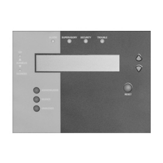
System Status Display with Control
ON
AUDIBLES
ON
OFF
BUTTON ENABLE
SILENCE
UNSILENCE
Figure 1
SSD-C System Status Display
Siemens Building Technologies
Fire Safety
Advertisement
Table of Contents

Related Manuals for Siemens SSD-C


Summary of Contents for Siemens SSD-C
-
Page 1: Installation Instructions
Installation Instructions Models SSD-C / SSD-C-INTL System Status Display with Control ALARM SUPERVISORY SECURITY TROUBLE AUDIBLES SILENCED ACKNOWLEDGE RESET BUTTON ENABLE SILENCE UNSILENCE Figure 1 SSD-C System Status Display Siemens Building Technologies Fire Safety... - Page 2 Display Siemens Building Technologies P/N 315-048733-3 Fire Safety...
- Page 3 NACs in the system are in supervisory mode. When the SOUNDER DISABLE option is selected in the Zeus Programming Tool, the sounder remains OFF , regardless of the status of the system. Siemens Building Technologies P/N 315-048733-3 Fire Safety...
- Page 4 ALARM SUPERVISORY SECURITY TROUBLE MOST RECENT MOST RECENT MOST RECENT MOST RECENT FIRST FIRST FIRST FIRST ALARM SUPERVISORY SECURITY TROUBLE ALARM SUPERVISORY SECURITY TROUBLE Figure 2 Event Priority - United States and Canada Siemens Building Technologies P/N 315-048733-3 Fire Safety...
- Page 5 16, 2002 , 04:15:25pm alarm 3-45 custom message for this alarm ack’d smoke 001 of 200 alm=200 supv=000 sec=000 trbl=000 Figure3 SSD-C LCD - Supervisory Mode (Top) and Active Event Mode (Bottom) Siemens Building Technologies P/N 315-048733-3 Fire Safety...
- Page 6 Figure 4 SSD-C Switch Location If the SSD-C is located at the end of the wire, add the terminating resistance to the communication wire by setting SW1 and SW2 to the ON position. This allows the NIC-C to properly supervise the communication wires.
- Page 7 14 - 18 AWG SSD-C 2. No EOLR required. S1-1, S1-2 has to be on the ON position if the SSD-C is at the end of the Style 4 or Style 7 network. PSC-12 3. Use twisted pair or twisted...
- Page 8 – CABLE EARTH TO SSD GROUND PSC-12 MAIN SSD-TB – Figure 6 Wiring The SSD-C DOUBLE GANG BOX 3 1/2-INCHES DEEP ( A 4-INCH SQUARE BOX MOUNTING PLATE 2 1/8-INCHES DEEP CAN ALSO BE USED) SSD ASSEMBLY OVERLAY Figure 7...
- Page 9 An auxiliary regulated power-limited power supply may be used to provide power to the SSD. The power supply must be UL approved for Fire Protection Signaling Application. Be sure to include the SSD-C in the battery calculations. Siemens Building Technologies P/N 315-048733-3...
- Page 10 Siemens Building Technologies, Inc. Siemens Building Technologies, Ltd. 8 Fernwood Road 2 Kenview Boulevard Florham Park, New Jersey 07932 Brampton, Ontario L6T 5E4 CN P/N 315-048733-3...
Need help?
Do you have a question about the SSD-C and is the answer not in the manual?
Questions and answers
on the SSD-C can you buy replacement buttons for the silence/unsilence/acknoledge buttons