GME CM40 Series Service Manual
Commercial analogue mobile radios
Hide thumbs
Also See for CM40 Series:
- Instruction manual (42 pages) ,
- Programming manual (32 pages) ,
- Reference manual (33 pages)

Related Manuals for GME CM40 Series


Summary of Contents for GME CM40 Series
- Page 1 CM40 & CM50 Series Commercial Analogue Mobile Radios C M 4 0 & C M 5 0 S E R V I C E M A N U A L SERVICE MANUAL...
-
Page 2: Table Of Contents
CONTENTS Radio Frequency Exposure Hazard ................4 Specifications ........................ 5 General ............................5 Transmitter ...........................5 Receiver ............................6 Audio .............................6 Mechanical ............................6 Models .......................... 7 Overview ............................7 Available Models ...........................7 Description ........................8 Overview ............................8 Physical Description ........................8 Local Setup ...........................8 Remote Setup ..........................10 Extended Setup ..........................10 Technical Description ........................13 Microprocessor ...........................17... - Page 3 Selective Calling: .........................62 Emergency Channels: (Applies to Australia only) ...............62 Telemetry Channels: ........................62 GME Warranty Against Defects .................. 63 C M 4 0 & C M 5 0 S E R V I C E M A N U A L...
-
Page 4: Radio Frequency Exposure Hazard
RADIO FREQUENCY EXPOSURE HAZARD Attention This radio should be used only in an occupational (work related) environment where the user is aware of and able to exercise control over their exposure to RF energy. To ensure your safety please read the following information before installing and using the radio. •... -
Page 5: Specifications
SPECIFICATIONS General Type CM40 CM50 Frequency Band UHF 450-520 MHz UHF 450-520 MHz VHF 136 - 174MHz Number of Channels 199 (80 CB) 2000 (80 CB) Number of Zones Channel Spacing 12.5 kHz Channel Steps 12.5kHz, 6.25kHz, 5kHz, 2.5kHz Frequency Stability ±1.5ppm for -20°C to 60°C Modulation Antenna Impedance... -
Page 6: Receiver
SPECIFICATIONS Receiver Type CM40 CM50 Circuit Type Double Conversion Superheterodyne, DC coupled, DSP audio processing IF Frequencies 21.4Mhz (VHF) 38.85 MHz (UHF) 450KHz Analog Sensitivity -122dBm for 12dB SINAD unweighted Adjacent Channel Selectivity 60 dB Spurious Rejection 80 dB Intermodulation Rejection 75 dB Blocking 100 dB... -
Page 7: Models
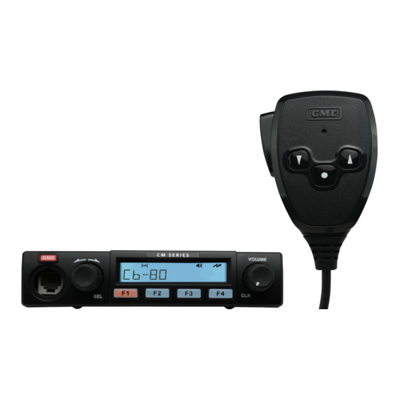
MODELS Overview The CM40 mobile is available in UHF (450-520 MHz) and has a maximum 5W transmission power. The CM50 series is available in UHF (450-520 MHz) and VHF (136-174 MHz) and has a maximum 25W transmission power. Available Models Radios The table below lists the CM40 &... -
Page 8: Description
UIC600 Advanced Controller Microphone The UIC600 advanced controller microphone has the following keys: • • Power • F1 - F5 Programmable keys • Emergency • Up scroll • A button • Volume up • Down scroll • B button • Volume down •... - Page 9 Extension Antenna RJ12 Rear Socket Speaker Socket (Factory used only) 12VDC connection Figure 2: Local Control CM40/50 Radio Rear View NOTE: The RJ12 Rear Socket does not support TX/RX Audio and is for Factory use only Call Programmable Key Microphone Up Key Down Key Programmable Key...
-
Page 10: Remote Setup
Remote Setup NOTE: The RJ45 socket on the remote control panel is only used with a UIC500/600 controller microphone or the RH006 Remote Head. RJ45 socket Figure 4: Base Radio Front View Rotate for channel control/ Volume control/CLR Push SEL Push for Function A for Function B Function Function... - Page 11 Programable Button / Emergency Microphone B button CLR (clear) F1 Programmable F2 Programmable Volume up/down F3 Programmable Up/down Scroll Keys F4 Programmable Backlit keypad Alphanumeric keys Figure 7: UIC500 Controller Microphone C M 4 0 & C M 5 0 S E R V I C E M A N U A L...
- Page 12 Emergency button Power button Microphone Status LED F4 Programmable B button CLR (clear) Up/down Scroll Keys F1 Programmable A button SEL (Select) F2 Programmable F5 Programmable F3 Programmable Volume up/down Backlit keypad Alphanumeric keys Figure 8: UIC600 Controller Microphone S E R V I C E M A N U A L C M 4 0 &...
-
Page 13: Technical Description
Technical Description Power Supply The CM40/50 radios are designed to operate from a nominal 13.8V DC power source via DC input socket SK901. Excessive voltage and reverse polarity protection are provided by asymmetrical suppression diode D902. +3.3V Supply The +3.3V supply is obtained from the +13.8V_SWITCHED supply using the DC/DC converter IC U903 which performs PWM regulation control. - Page 14 +5V Supply The +5V supply is generated from the +13.8V_SWITCHED power supply using the 5V linear regulator U902. It supplies power to: • DAC U806 • IF IC U301 • Op-amps U701, U807 • Buffers U804, U805 • Switches U303, U304 Figure 11: +5V Power Supply +8V Supply The +8V supply is generated from the +13.8V_SWITCHED power supply using the 8V linear regulator...
- Page 15 The +8VTX is switched by Q905 and Q907 and supplies power to the following: • TX Driver U601 • Antenna Switch Q601 • ALC Op-amp U603 Figure 13: +8VTX Switched Supply +3.3VPLL Supply The +3.3VPLL supply is generated from the +8V supply using the 3.3V linear regulator U503. It provides a clean 3.3V supply to the following: •...
- Page 16 +13.8V_Filtered Supply (25W UHF/VHF) Transistors Q901 and Q902 are configured as an active impulse noise reject filter. The output voltage of this circuit follows the average negative peak of the battery voltage with a small adjustable offset. Positive spikes are suppressed. Feedback is provided by the error amplifier Q902 and its collector current drives the pass transistor Q901.
-
Page 17: Microprocessor
Microprocessor The CPU is a dsPIC 16-bit combined CPU and DSP device. The 16MHz crystal XT801 is used to generate the CPU timing clock. Power is provided by the 3.3V switching regulator U903. The resistive divider R913, R914 is used to generate the power fail signal at pin 24. The CPU regularly reads this pin to ensure that the +13.8V supply is sufficiently maintained. -
Page 18: Voltage Controlled Oscillator (Vco)
Voltage Controlled Oscillator (VCO) VCO is a conventional common collector stage based around Q101. The main tuning elements are the capacitor C109, inductor L103 and the microstrip inductor between L103 and ground. Frequency tuning is achieved by varactors (UHF: D103-106, VHF: D103-D108). When in transmit mode, the transistor Q105 switches on the diode D102. -
Page 19: Antenna Switching
Antenna Switching The antenna RX/TX switching is achieved using two switching diodes, D603 and D605. The low pass filter (LPF) that connects the antenna to this switch attenuates out-of-band signals and provides impedance matching between the TX output module U602 and the antenna. In receive mode, Q601 is off and D603, D605 are reverse biased. - Page 20 RF Amplifier Cont. Following the LNA is a 3-section parallel LC tank. This forms a band pass filter (BPF) centered around the receive frequency, rejecting out-of-band signals. The BPF is tuned using varactors D203-205. Tuning voltages for the notch and BPFs are supplied by the DAC U806. Figure 22: UHF Band Pass Filter First Mixer and IF Section After the BPF, the signal passes to the first mixer stage.
-
Page 21: Receiver - Vhf
FM Demodulator FM demodulation is performed by the IF IC U301. The 38.85MHz signal is coupled to the RF input of U301 where it is mixed with the 38.4MHz oscillator signal generated by XT301. This produces a second IF signal at 450kHz. The second IF signal is then switched to either the wideband ceramic filter CF301 or narrowband ceramic filter CF303 using the switch ICs U303, U304. - Page 22 Figure 25: VHF First Mixer FM Demodulator FM demodulation is performed by the IF IC U301. The 21.4MHz signal is coupled to the RF input of U301 where it is mixed with the 20.95MHz oscillator signal generated by XT301. This produces a second IF signal at 450 kHz.
-
Page 23: Audio Power Amplifier
Audio Power Amplifier The filtered FM audio from the CODEC is coupled to the input of the audio amplifier U401. This amplifier is configured to have a flat frequency response. The output of the amplifier is coupled to the internal speaker J402 and external socket J401. The amplifier is placed in standby mode when Q402 is driven on by the CPU, pulling pin 8 of the audio amplifier low. - Page 24 Figure 27: 25W UHF Power Amplifier Figure 28: VHF Power Amplifier S E R V I C E M A N U A L C M 4 0 & C M 5 0...
-
Page 25: Connectivity
Connectivity Front Panel Connector J802 provides connectivity between the radio base and the radio control interface. It carries the +13.8V supplies, microphone audio, volume control signals and UART RX/TX. The level converters U804 and U805 convert the CPU 3.3V UART interface to 5V for the front panel. Figure 29: J802 Controller Connector Wireless Header Connector J806 is a socket into which expansion modules may be plugged to extend radio... - Page 26 Auxiliary Interface Connector J801 is a socket intended for use with auxiliary cables. The cables provide an interface for external control of the radio for third-party applications. It carries the +13.8V_SWITCHED supply, RS232 level RX/TX, PTT input, BUSY output, TX/RX audio and several reconfigurable I/Os. Figure 31: CM Series Auxiliary Connector J801 Note: Refer to the CM Series AT Command Reference Manual for working instructions on available...
- Page 27 Name Description Levels AUX_PTT PTT indicator to radio. 0 to supply voltage (+13.8V). Active low. AUX_BUSY Busy out indicator from radio. 0 to +3.3V. Programmable polarity and function. RS232_RX Serial transmit from DTE to radio. -15 to +15V. 0 (space): +2.4 to +15V. 1 (mark): -15 to +1.2V.
- Page 28 AUXILIARY LEAD DIAGRAMS LE111: Ignition Sense Lead (RS232) to suit CM Series 8 ±2mm 1.0mm 10mm PIN 1 IDENTIFIER PIN 19 PIN 20 16mm 35 ±2mm PIN 1 PIN 2 335 ±10mm 48mm PIN 1 (END VIEW) (END VIEW) BLACK BROWN BLACK ORANGE...
- Page 29 AUXILIARY LEAD DIAGRAMS LE114: 1M Auxiliary Cable with DB25 (Male) Connector to suit CM Series 1000.0 10.0mm 60.0 5.0mm DB25 Male SHDR-20V-S-B 25.0mm CON2 DB25 TX AUDIO - DC COUPLED TX AUDIO - DC COUPLED RSSI CON1 ALARM SHDR-20V-S-B RS232 RX AUX PTT RS232 TX AUX BUSY...
-
Page 30: Installation
INSTALLATION Overview The CM40/50 radio is supplied with a slide-on mounting bracket. The bracket is screwed or bolted in a convenient location in a vehicle using the mounting slots provided in the base. The CM40/50 radio has a built-in speaker and may be installed with the speaker facing upwards or downwards to ensure the receiver audio is projected clearly. -
Page 31: Removing The Radio
Removing the Radio To remove the radio from the mounting bracket, pull the two tabs on either side of the mounting bracket outwards until the radio releases. Slide out the radio. Figure 35: Removing the Radio DC Power Connection The CM40/50 radio is designed for 13.8V DC, negative earth installations only (i.e. where the nega- tive terminal of the battery is connected to the chassis or frame of the vehicle). -
Page 32: Fitting And Removing The Mp600B Fist Microphone
Fitting and Removing the MP600B Fist Microphone The MP600B fist microphone is supplied with a mounting clip. Screw the MP600B microphone mounting clip to a firm surface. The MP600B microphone uses an RJ12 6-pin style plug and socket. To fit the MP600B microphone: Position the MP600B microphone plug so the plastic tab faces downwards. -
Page 33: Fitting And Removing A Uic500/600 Controller Microphone
Fitting and removing a UIC500/600 Controller Microphone Screw the UIC500/600 controller microphone mounting clip to a firm surface. The UIC500/600 con- troller microphone uses an RJ45 style plug and socket. To fit the UIC500/600 controller microphone, position the UIC500/600 controller microphone plug so the plastic tab faces downwards. -
Page 34: Alignment
ALIGNMENT Alignment Procedure The equipment required to perform the alignment procedure is listed below. • Radio communications test set • 13.8V DC power supply • LS1-USB programming cable • LS002 programming adapter (local/control head) • LS003 programming adapter (base radio) •... - Page 35 Turn the radio on. Run CM40.exe/CM50.exe to open the CM40/50 series radio programmer software. Figure 42: GME Radio Programmer Message Click OK. Figure 43: GME Radio Programmer Ensure correct port settings using Program > Serial Port Auto Detect.
-
Page 36: Transmitter Center Frequency Alignment
Transmitter Center Frequency Alignment To align transmitter center frequency: Select the Frequency tab. Set the radio to an analog channel. Or select an option from Alignment Frequency. Set the service monitor to transmitter test mode. Click the PTT button in the upper left of the screen. The radio will switch to transmit mode. -
Page 37: Receive Frequency Dc Offset Alignment
Receive Frequency DC Offset Alignment To align receive frequency DC offset: Select the Frequency tab. Set the radio to an analog channel, or select Frequency from Alignment Frequency options. Set the service monitor to Receiver Test mode. Inject a -70dBm unmodulated signal into the radio from the service monitor at the alignment frequency. -
Page 38: Transmitter Output Power Alignment
Transmitter Output Power Alignment To align transmitter output power: Select the Transmitter tab. Select the 25W output in the Power Output section. Select the frequency under the Alignment Frequency section. Click the PTT button at the upper left of the screen to transmit. Change the Power Adjust value for the chosen alignment frequency until the service monitor reads 25W. -
Page 39: Transmitter Deviation/Modulation Alignment
Transmitter Deviation/Modulation Alignment Note: Ensure that the Transmit Modulation AF Filter has been correctly set on test equipment (15kHz LPF recommended). To align transmitter modulation: FOR BALANCE Click the Transmitter tab. Set the radio to an analog channel, or select frequency in the Alignment Frequency section. -
Page 40: Receiver Front-End Band Pass Alignment - Uhf
Receiver Front-End Band Pass Alignment - UHF To align receiver band pass filter alignment - UHF RSSI polling method: Select the Receiver tab. Set the radio to an analog channel, or select the frequency from the Alignment Frequency options. Select the first frequency option in the Alignment Frequency section. Set the service monitor to RF Generate. - Page 41 Figure 48: UHF Receiver BPF Alignment C M 4 0 & C M 5 0 S E R V I C E M A N U A L...
-
Page 42: Receiver Band Pass Filter Alignment - Vhf
Receiver Band Pass Filter Alignment - VHF To align receiver band pass filter - VHF RSSI polling method: Select the Receiver tab. Set the radio to an analog channel, or select the frequency from Alignment Frequency options. Select the first option in the Alignment Frequency section. Set the service monitor to RF Generate. -
Page 43: Receiver S-Meter Alignment
Receiver S-Meter Alignment To align the receiver S-meter: Select the S-meter tab. Select the second option in the Alignment Frequency section. Inject a -121dBm signal into the radio from the service monitor at the alignment frequency. Click the Set S1 button. Inject a -73dBm signal into the radio from the service monitor at the alignment frequency. -
Page 44: Vco Control Voltage Check
VCO Control Voltage Check Required equipment also includes a CRO (Oscilloscope) or DVM (Digital Voltage Meter) for measuring VCO Control Voltage. Figure 51: VCO Control Voltage Test Point (PCB Bottom View) To check VCO control voltage for UHF: Click Align to open the alignment screen. Select the Transmitter tab. -
Page 45: Parts List
PARTS LIST CM40/50 Radio Parts List: Mechanical Part Number Description Circuit Reference 46A0439 Clamp - DC Lead Clip 730171 Connector - 20 Way HST SHD Aux Socket SMD J801 730170 Connector - 40 Way Hirose DF12 P25 Socket SMD J805 730135 Connector - 8 Pin [Interconnect Board] J901... -
Page 46: Cm40/50 Radio Parts List: Electrical
PARTS LIST CM40/50 Radio Parts List: Electrical Part Number Description Circuit Reference 10A027 Filter - 450KHz C24 CF302 10A029 Filter - CFWM450E CF301 10A047 Filter - LTM450IW CF303 77MAX3232E U803 77R2A20168 U806 77UMD3N Q105 Q205 Q206 Q904 Q906 77MCP6002M IC - Amplifier U701 U703 U807 77MCP6002T IC - Amplifier... -
Page 47: Cm40/50 Radio Parts List: Electrical
PARTS LIST CM40/50 Radio Parts List: Electrical Part Number Description Circuit Reference 77BC817W Transistor Q601 Q804 77BC847BW Transistor Q104 Q502 Q503 Q902 77BC857CW Transistor Q501 77PDTC114T Transistor Q402 Q801 Q805 Q807 Q907 56SMD14 Trim Pot 10K RV901 771SV276 Diode D501 D503 771SV304 Diode D103 D104 D105 D106 D107 D108... -
Page 48: Pcb Layouts
PCB LAYOUTS CM40-UHF-5W (Top View) Figure 52: Top view of the PCB 580461-6 S E R V I C E M A N U A L C M 4 0 & C M 5 0... -
Page 49: Cm40-Uhf-5W (Bottom View)
PCB LAYOUTS CM40-UHF-5W (Bottom View) Figure 53: Bottom view of the PCB 580461-6 C M 4 0 & C M 5 0 S E R V I C E M A N U A L... -
Page 50: Cm50-Uhf-25W (Top View)
PCB LAYOUTS CM50-UHF-25W (Top View) Figure 54: Top view of the PCB 580443-6 S E R V I C E M A N U A L C M 4 0 & C M 5 0... -
Page 51: Cm50-Uhf-25W (Bottom View)
PCB LAYOUTS CM50-UHF-25W (Bottom View) Figure 55: Bottom view of the PCB 580443-6 C M 4 0 & C M 5 0 S E R V I C E M A N U A L... -
Page 52: Cm50-Vhf-25W (Top View)
PCB LAYOUTS CM50-VHF-25W (Top View) Figure 56: Top view of the PCB 580485-07 S E R V I C E M A N U A L C M 4 0 & C M 5 0... -
Page 53: Cm50-Vhf-25W (Bottom View)
PCB LAYOUTS CM50-VHF-25W (Bottom View) Figure 57: Bottom view of the PCB 580485-7 C M 4 0 & C M 5 0 S E R V I C E M A N U A L... -
Page 54: Block Diagrams
BLOCK DIAGRAMS CM40-UHF-5W Figure 58: CM40-50 UHF Block diagram S E R V I C E M A N U A L C M 4 0 & C M 5 0... -
Page 55: Cm50-Uhf-25W
BLOCK DIAGRAMS CM50-UHF-25W Figure 59: CM50 VHF Block Diagram C M 4 0 & C M 5 0 S E R V I C E M A N U A L... -
Page 56: Cm50-Vhf-25W
BLOCK DIAGRAMS CM50-VHF-25W S E R V I C E M A N U A L C M 4 0 & C M 5 0... -
Page 57: Circuit Diagrams
CIRCUIT DIAGRAMS CM40-UHF-5W C M 4 0 & C M 5 0 S E R V I C E M A N U A L... -
Page 58: Cm50-Uhf-25W
CIRCUIT DIAGRAMS CM50-UHF-25W S E R V I C E M A N U A L C M 4 0 & C M 5 0... -
Page 59: Cm50-Vhf-25W
CIRCUIT DIAGRAMS CM50-VHF-25W C M 4 0 & C M 5 0 S E R V I C E M A N U A L... -
Page 60: Notices & Warnings
NOTICES & WARNINGS Copyright Notice: GME Pty Ltd reserves all rights to this document and the information contained herein. Reproduction, use or disclosure to third parties without express permission is strictly prohibited. © 2021 GME Pty Ltd, Sydney, Australia S E R V I C E M A N U A L... -
Page 61: Postface
POSTFACE Information Concerning UHF CB Radio: IMPORTANT The use of the Citizen Band radio service is licensed in Australia by the ACMA Radio communications (Citizens Band Radio Stations) Class Licence and in New Zealand by the Ministry of Economic Development New Zealand (MED). A General User Radio Licence for Citizens Band radio and operation is subject to conditions contained in those licences. -
Page 62: Selective Calling
The Duplex function can only be selected on UHF CB channels 1 - 8 and 41 - 48 as these are the channels that have been allocated for repeater use. When Duplex is selected, your radio receives on the selected channel (e.g. CH 1) but transmits 30 channels higher (CH 31). The repeater hears your signal on CH 31 and retransmits it on CH 1 for others to hear. -
Page 63: Gme Warranty Against Defects
GME WARRANTY AGAINST DEFECTS This warranty against defects is given by GME Pty Ltd ACN 000 346 814 (We, us, our or GME). Our contact details are set out in clause 2.7. This warranty statement only applies to products purchased in Australia. Please contact your local GME distributor for products sold outside of Australia. - Page 64 A customer support team member will troubleshoot and validate if your product is faulty. If so, they will email you a product RMA (Return Material Authorisation). Products that are authorised to be returned to GME must include the following: RMA form (Return Material Authorisation) A copy of your proof of purchase, the faulty product, including all accessories 2.7 Send your claim to:...
- Page 65 GME Pty Ltd. DEC 2023 17 Gibbon Road, Winston Hills NSW 2153, Australia D/N: 52957-1...
Need help?
Do you have a question about the CM40 Series and is the answer not in the manual?
Questions and answers