GME CM40 Series Instruction Manual
Commercial analogue mobile radios
Hide thumbs
Also See for CM40 Series:
- Programming manual (32 pages) ,
- Service manual (65 pages) ,
- Reference manual (33 pages)
Table of Contents
Advertisement
Quick Links
Advertisement
Table of Contents

Subscribe to Our Youtube Channel
Related Manuals for GME CM40 Series


Summary of Contents for GME CM40 Series
- Page 1 CM40 & CM50 Series Commercial Analogue Mobile Radios INSTRUCTION MANUAL...
-
Page 2: Table Of Contents
CONTENTS INTRODUCTION: SETTINGS: Available Configurations Alert Level Key Features Beep Level Supplied Configurations Key Tones Controls Channel Info Display GENERAL OPERATION: Functions Turning the Radio On/Off & Volume Lock Radio Adjusting the Speaker Volume Squelch Level Selecting Channels TX Power Screen Display Radio Info Display Symbols... -
Page 3: Introduction
INTRODUCTION The CM40 and CM50 have been designed and made in Australia by GME Pty Ltd specifically to meet the requirements of commercial radio users. Please read this user manual thoroughly. It provides information on the features, parts, controls and specifications of the CM40 and CM50 radios. -
Page 4: Supplied Configurations
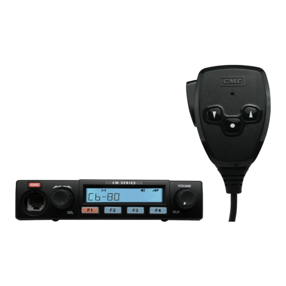
SUPPLIED CONFIGURATIONS CM40 Series: Standard Configuration CM40-U5 MP600B Heavy Duty IP67 Fist Mic to suit CM & TX Series MB009 Mounting Bracket for CM & TX Series LE09 1.8M DC Lead to suit 5W CM & TX Series CM50 Series :... -
Page 5: Controls
CONTROLS The instructions below describe the locations and defult functions of the controls on the fixed mount radio and microphones. Each of these controls have been configured by your dealer for your application. If required, please refer to your dealer for more detailed operating instructions relating to the specific programming of your radio. - Page 6 UIC600 Microphone Controls When using the UIC600 Controller Microphone, the CM50 base radio must be fitted with a remote- control panel. The front of the CM50 base radio will have no controls, the UIC600 controller microphone is connected into the socket and controls all functions of the CM50 radio through assigned keys/ buttons.
-
Page 7: General Operation
GENERAL OPERATION Please refer to the diagrams on the Controls page for a general description of the controls and keys. PROGRAMMABLE KEYS: The dealer can assign control functions to programmable keys on the radio. Contact the dealer or refer to the Programmable Keys Control Functions section of this manual for more information. Turning the Radio On/ Off &... -
Page 8: Selecting Channels
To adjust the volume on the UIC600 Controller Microphone use the Up/ Down Volume Buttons. Volume Up/Down Selecting Channels: Local/ Control Head: Select Channels from the main menu, rotate the A Button (Channel Selector) to locate the desired channel then press the Push-to-Talk (PTT). Controller Microphone: Select Channels from the main menu, use the Up/ Down Arrows to locate the desired channel then press the Push-to-Talk (PTT). -
Page 9: Screen Display
DISPLAY The radio and the controller microphone displays the current menu and the status of the radio. When a menu is not accessed, the radio displays information such as the channel that is currently selected. Screen Display The radio screen display on the local/ remote control head control. The screen display on the controller microphone. -
Page 10: Leds
LEDs The controller microphone is fitted with an LED light that displays different colours depending on the radio status. The table below explains the meaning of the LED light colours. Colour State/Action The radio is transmitting. Green The radio is receiving a call. Orange Emergency mode is active and the radio is not transmitting or receiving calls. -
Page 11: Advanced Operation
ADVANCED OPERATIONS START UP DISPLAY The screen will display the last selected channel. Press the A Button to access the main menu. Channels A channel contains frequencies the radio uses to transmit and receive signals. The Channels menu displays a list of channels that are available in the currently selected zone. To access the Channels menu: 1. -
Page 12: Recent Calls
Recent Calls This feature lists the 20 most recent calls made, received or missed by displaying the corresponding Call ID or Unit ID. The most recent call is displayed first on the list. Select a Call/ Unit ID on this list to call back. -
Page 13: Selcall
Selcall (Selective Calling) Selective Calling is an analog signaling technology which operates like a telephone where a call to a specific radio uses the custom unique ID of the radio. SellCall supports 48 unique idents, with up to 11 characters of alpha text to be displayed. To access the Selcall menu: 1. -
Page 14: Send Dtmf
Send DTMF DTMF (Dual Tone Multiple Frequency) is an analog signaling system used to connect to a telephone network by a telephone interconnect device. The Send DTMF option sends a predefined string of DTMF tones for keying up a repeater. DTMF supports 15 unique tone sequences of up to 16 tones each. -
Page 15: Services
SERVICES The Services menu becomes available only if Digital Selcall is enabled. Digital Selcall (MDC1200) is a digital signalling technology that is used for analog channels. The CM40 and CM50 series programming manual contains information on configuring the radio to use digital selcall. Services provide features that are listed and described in the table below. -
Page 16: Send Msg
Send MSG The Send MSG (Send Message) feature provides a list of predefined short messages that can be broadcast to other radio operators to indicate an event or make a request. To access the Send MSG menu: 1. Select Services from the main menu. 2. -
Page 17: Send Alert (Page)
Send Alert (Page) The Send Alert feature allows for an alert to be sent to another radio requesting communication. To access the Send Alert menu: 1. Select Services from the main menu. 2. Select Send Alert. 3. Press the A Button to select or the B Button to go back. SEND MSG SEND ALERT send alert... -
Page 18: Send Status
Send Status The Send Status feature provides a list of predefined status messages that can be broadcast to other radio operators to inform them of the user’s current status. To access the Send Status menu: 1. Select Services from the main menu. 2. -
Page 19: Set Status
Set Status The Set Status option allows selection and setting a status message that indicates the radio’s current status. The selected message remains set in the radio until updated with another message. When the radio receives a status request message it will reply by broadcasting the currently stored status, allowing other users to query the radio’s current status. -
Page 20: Status Request
Status Request The Status Request option allows a signal to be sent to another radio asking for a status update. The Status Request option allows access to a list of predefined radio IDs to send a request to. To access the Set Request menu: 1. -
Page 21: Check Request
Check Request The Check Request feature sends a radio check message to confirm whether a radio is within communication range. To access the Check Request menu: 1. Select Services from the main menu. 2. Select Check Request. 3. Press the A Button to select or the B Button to go back. The first item displayed is ENTER ID if Check Request is selected. -
Page 22: Inhibit Request
Inhibit Request A radio that is configured with this feature can send an Inhibit Request that prevents a selected radio from operating. The Inhibit Request feature may also be known as Stun. To access the Inhibit Request menu: 1. Select Services from the main menu. 2. -
Page 23: Uninhibit Request
Uninhibit Request A radio that is configured for this feature can send an Uninhibit Request to an inhibited radio allowing it to resume operation. The Uninhibit Request feature may also be known as Revive. To access the Uninhibit Request menu: 1. -
Page 24: Settings
SETTINGS The Settings option contains a list of options that can be set for the radio. To access the Settings menu: 1. Select Settings from the main menu. 2. Press the A Button to select or the B Button to go back to the previous menu. SELCALL SEND DMTF settings... -
Page 25: Beep Level
Beep Level The Beep Level option allows you to set the level of the beep tone. beep 5 BEEP 5 Accept Back UIC600 Microphone Display Radio Display To access the Beep Level: 1. Select Settings from the main menu 2. Select Alert Level. 3. -
Page 26: Channel Info
Channel Info The Channel Info displays the configuration information for the set channel. 1. Press the A Button to access the menu. ALERT LEVEL CHAN INFO chan info FUNCTIONS Select Back UIC600 Microphone Display Radio Display 2. Use the A Button (Selector Knob) on the local head, or the Up/ Down Arrows on the controller microphone to scroll the information on the display. -
Page 27: Functions
Functions The Functions menu allows access to functions such as Locking the Radio, Squelch Level and Transmission Power. To access the Functions menu: 1. Select Settings from the main menu. 2. Select Functions. CHAN INFO FUNCTIONS functions RADIO INFO Select Back UIC600 Microphone Display Radio Display... -
Page 28: Squelch Level
To Unlock the radio: 1. Press the A Button to access the Unlock option. 2. Press the A Button again to unlock the radio. The radio may require a PIN to unlock if configured for PIN entry. For information on how to change the PIN. Refer the Change PIN section of this manual. unlock UNLOCK? Accept... -
Page 29: Tx Power
TX Power The TX Power option allows you to set the radio’s maximum transmission power level. LOCK RADIO SQUELCH LVL TX POWER TX POWER Select Back UIC600 Microphone Display Radio Display To access TX Power: 1. Select Settings from the main menu. 2. -
Page 30: Change Pin
Change PIN The Change PIN option allows the PIN used to lock and unlock the radio to be changed. To access Change PIN: 1. Select Settings from the main menu. 2. Select Radio Info. 3. Select Change PIN. 4. The screen displays the message ENTER PIN. To change the PIN on the controller microphone: 1. -
Page 31: Serial Number
Serial Number The Serial Number option displays the radio’s serial number. To access Serial No: 1. Select Settings from the main menu. 2. Select Radio Info. 3. Select Serial No. MAC ADDR MSM VERSION serial no SERIAL NO Select Back UIC600 Microphone Display Radio Display 4. -
Page 32: Main Speaker
Main Speaker To access Main Speaker: 1. Select Settings from the main menu. 2. Select Speakers. 3. Select Main Spk. MAIN SPK AUX SPK main spk Select Back UIC600 Microphone Display Radio Display To set the Mute/Unmute Main Speaker: 1. Press the A Button to select MUTE to mute main speaker. 2. -
Page 33: Diagnostics
DIAGNOSTICS The Diagnostics option allows access to view the Radio’s Frequency and RSSI. To access the Diagnostics option:: 1. Select Diagnostics from the main menu. TRUNKING SETTINGS diagnostics DIAGNOSTICS Select Back UIC600 Microphone Display Radio Display There are two options available for this feature: •... -
Page 34: Rssi
RSSI The RSSI (Received Signal Strength Indication) option displays the received signal strength of the current channel. The signal strength is expressed in decibels (dBm). The higher the dBm number, the stronger the signal. To view the radio RSSI: 1. Select Diagnostics from the main menu 2. -
Page 35: Menu Tree
MENU TREE Channels Zones Recent Call Recent Message Selcall Send DTMF Services* Send Message Send Alert Se�ngs Alert Level Beep Level Send Status Channel Info Key Tones Set Status Display** Status Request Func�ons Lock Radio Check Request Squelch Level TX Power Inhibit Request Radio Info F/W Version... -
Page 36: Notices & Warnings
NOTICES & WARNINGS Copyright Notice: GME Pty Ltd reserves all rights to this document and the information contained herein. Reproduction, use or disclosure to third parties without express permission is strictly prohibited. © 2021 GME Pty Ltd, Sydney, Australia Interference with Vehicle Electronics Some of the electronics in your vehicle may be susceptible to RF energy when your radio is transmitting. -
Page 37: Postface
POSTFACE Information Concerning UHF CB Radio: IMPORTANT The use of the Citizen Band radio service is licensed in Australia by the ACMA Radio communications (Citizens Band Radio Stations) Class Licence and in New Zealand by the Ministry of Economic Development New Zealand (MED). A General User Radio Licence for Citizens Band radio and operation is subject to conditions contained in those licences. - Page 38 The Duplex function can only be selected on UHF CB channels 1 - 8 and 41 - 48 as these are the channels that have been allocated for repeater use. When Duplex is selected, your radio receives on the selected channel (e.g. CH 1) but transmits 30 channels higher (CH 31). The repeater hears your signal on CH 31 and retransmits it on CH 1 for others to hear.
-
Page 39: Warranty
GME WARRANTY AGAINST DEFECTS This warranty against defects is given by GME Pty Ltd ACN 000 346 814 (We, us, our or GME). Our contact details are set out in clause 2.7. This warranty statement only applies to products purchased in Australia. Please contact your local GME distributor for products sold outside of Australia. - Page 40 A customer support team member will troubleshoot and validate if your product is faulty. If so, they will email you a product RMA (Return Material Authorisation). Products that are authorised to be returned to GME must include the following: RMA form (Return Material Authorisation) A copy of your proof of purchase, the faulty product, including all accessories 2.7 Send your claim to:...
-
Page 41: Notes
NOTES C M 4 0 & C M 5 0 I N S T R U C T I O N M A N U A L... - Page 42 GME Pty Ltd. 17 Gibbon Road, Winston Hills NSW 2153, Australia OCT 2021 P/N: N/A D/N: 52250-1...
Need help?
Do you have a question about the CM40 Series and is the answer not in the manual?
Questions and answers