Table of Contents
Advertisement
Quick Links
Advertisement
Table of Contents

Related Manuals for GME CM1039


Summary of Contents for GME CM1039
- Page 1 CM1039 PROFESSIONAL SERIES MOBILE RADIO INSTRUCTION MANUAL...
- Page 2 Copyright Notice Standard Communications Pty Ltd reserves all rights to this document and the information contained herein. Reproduction, use or disclosure to third parties without the express permission is strictly prohibited. Copyright 2013 Standard Communications Pty Ltd Sydney, Australia RADIO FREQUENCY EXPOSURE HAZARD Attention This radio should be used only in an occupational (work related) environment where the user is aware of and able to exercise control over their exposure to RF energy. This radio is not authorized for use by the consumer or by the general population. To comply with the US FCC radio frequency guidelines and to ensure your safety please read the following information before installing and using the radio. • Use the radio only within the guidelines of this manual. • Use only with an approved antenna. • Do not remove the RF Exposure label from this radio. • Do not transit longer than the rated duty cycle of 50% talk‐50% listen. Radio Frequency Exposure Control This radio emits RF (Radio Frequency) energy or radio waves when transmitting. RF energy is one of many forms of electromagnetic energy including sunlight and electricity. The FCC Radio Frequency exposure guidelines include recommendations on the safe levels of exposure for workers and the general public with a significant margin of protection. To comply with FCC exposure limits the radio must be installed using an externally mounted antenna with a gain of either 2.15 dBi or 5.15 dBi. Transmit only when bystanders are at a minimum safe distance of 35 inches (0.9 m) from the antenna. For further information on RF energy exposure and how to control it, please visit the following website. www.fcc.gov/oet/rfsafety/rf‐faqs.html 2 ...
- Page 3 Compliance with RF Energy Standards This radio is designed and tested to comply with a number of national and international standards and guidelines (listed below) regarding human exposure to RF electromagnetic energy. This radio complies with the IEEE and ICNIRP exposure limits for occupational/controlled RF exposure environment at duty cycles of up to 50% talk‐50% listen and should be used for occupational use only. In terms of measuring RF energy for compliance with the FCC exposure guidelines, your radio radiates measureable RF energy only when it is transmitting (during talking), not when it is receiving (listening) or in standby mode. This radio complies with the following RF energy exposure standards and guidelines: • United States Federal Communications Commission, Code of Federal Regulations; 47CFR part 2 sub‐part J • American National Standards Institute (ANSI)/Institute of Electrical and Electronic Engineers (IEEE) C95. 1‐1992 • Institute of Electrical and Electronic Engineers (IEEE) C95. 1‐1999 edition • International Commission on Non‐Ionizing Radiation Protection (ICNIRP) 1998 FCC COMPLIANCE This equipment has been tested and found to comply with the limits for a Class B digital device, pursuant to part 15 of the FCC Rules. These limits are designed to provide reasonable protection against harmful interference in a residential installation. This equipment generates uses and can radiate radio frequency energy and, if not installed and used in accordance with the instructions, may cause harmful interference to radio communications. However, there is no guarantee that interference will not occur in a particular installation. If this equipment does cause harmful interference to radio or television reception, which can be determined by turning the equipment off and on, the user is encouraged to try to correct the interference by one or more of the following measures: • Reorient or relocate the receiving antenna. • Increase the separation between the equipment and receiver. • Connect the equipment into an outlet on a circuit different from that to which the receiver is connected. Consult the dealer or an experienced radio/TV technician for help. ...
- Page 4 USING THE RADIO IN EXPLOSIVE ATMOSPHERES OR BLASTING AREAS Switch off your radio before entering any area where there may be inflammable gas, liquids or dust. An explosion could result in serious injury or death. Switch off your radio when approaching a blasting area. Blasting areas are usually sign posted with instructions to users to turn off two way radios. Strong radio transmissions could ignite blasting caps resulting in an unscheduled explosion resulting in serious injury or death. INSTALLATION GUIDELINES • Do not install the radio near an airbag or in an area where an airbag may deploy. If an airbag is obstructed by the radio, it may not deploy as expected. It could also propel the radio with enough force to cause serious injury. • Avoid touching the heat sink at the rear of the radio while the radio is in use. The heat sink can become hot during prolonged use. • Do not install the radio in front of a vehicle heater. The radio requires a cool airflow over the rear heat sink when transmitting to maintain efficiency. • Do not make unapproved modifications to the radio. Such modifications could void the warranty and cause the radio to operate outside its approved specifications. Interference with Vehicle Electronics Some of the electronics in your vehicle may be susceptible to RF energy when your radio is transmitting. Examples of electronic devices in your vehicle that could be affected are anti‐ lock/anti‐skid braking systems, cruise control systems and fuel injection systems. If your vehicle is fitted with any of these systems please consult your vehicle manufacturer to determine whether these systems are likely to be affected by your radio when it is transmitting. Careful selection of mounting locations and good installation techniques should generally minimize any interference to your vehicle electronics. 4 ...
-
Page 5: Table Of Contents
CONTENTS INTRODUCTION. . . . . . . . . . . . . . . . . . . . . . . . . . . . . . . . . . . . . . . . . . . . . . . . . . . . . . . . . . . 6 FEATURES. . . . . . . . . . . . . . . . . . . . . . . . . . . . . . . . . . . . . . . . . . . . . . . . . . . . . . . . . . . 6 PRIMARY CONTROLS. . . . . . . . . . . . . . . . . . . . . . . . . . . . . . . . . . . . . . . . . . . . . . . . . . . . . . . . 7 Front Panel. . . . . . . . . . . . . . . . . . . . . . . . . . . . . . . . . . . . . . . . . . . . . . . . . . . . . . . . . 7 Rear Panel. . . . . . . . . . . . . . . . . . . . . . . . . . . . . . . . . . . . . . . . . . . . . . . . . . . . . . . . . 7 MC513BC Microphone. . . . . . . . . . . . . . . . . . . . . . . . . . . . . . . . . . . . . . . . . . . . . . . . 7 PROGRAMMABLE KEYS. . . . . . . . . . . . . . . . . . . . . . . . . . . . . . . . . . . . . . . . . . . . . . . . . . . . . . 8 MENU NAVIGATION. . . . . . . . . . . . . . . . . . . . . . . . . . . . . . . . . . . . . . . . . . . . . . . . . . . . . . . . 8 General. . . . . . . . . . . . . . . . . . . . . . . . . . . . . . . . . . . . . . . . . . . . . . . . . . . . . . . . . . . . 8 Menu Map. . . . . . . . . . . . . . . . . . . . . . . . . . . . . . . . . . . . . . . . . . . . . . . . . . . . . . . . . 9 GENERAL OPERATION. . . . . . . . . . . . . . . . . . . . . . . . . . . . . . . . . . . . . . . . . . . . . . . . . . . . . . 10 Backlight. . . . . . . . . . . . . . . . . . . . . . . . . . . . . . . . . . . . . . . . . . . . . . . . . . . . . . . . . . . 10 TX Power Level. . . . . . . . . . . . . . . . . . . . . . . . . . . . . . . . . . . . . . . . . . . . . . . . . . . . . . 10 Squelch. . . . . . . . . . . . . . . . . . . . . . . . . . . . . . . . . . . . . . . . . . . . . . . . . . . . . . . . . . . . 10 Squelch Level. . . . . . . . . . . . . . . . . . . . . . . . . . . . . . . . . . . . . . . . . . . . . . . . . . . . . . . 11 Beep Volume. . . . . . . . . . . . . . . . . . . . . . . . . . . . . . . . . . . . . . . . . . . . . . . . . . . . . . . 11 Firmware Version. . . . . . . . . . . . . . . . . . . . . . . . . . . . . . . . . . . . . . . . . . . . . . . . . . . . 12 Radio Serial Number. . . . . . . . . . . . . . . . . . . . . . . . . . . . . . . . . . . . . . . . . . . . . . . . . . 12 Selective Call. . . . . . . . . . . . . . . . . . . . . . . . . . . . . . . . . . . . . . . . . . . . . . . . . . . . . . . . 12 ... -
Page 6: Introduction
INTRODUCTION The GME CM1039 Series is a 25W Commercial radio which will operate in the VHF 136 – 174 MHz, UHF(H) 450MHz – 512MHz and UHF(L) 403MHz – 470MHz bands. GME CM1039 Series radios represent a significant opportunity for both large and small network operators to effectively future proof their communications systems. The CM1039 series of mobile radios permits fleet transition from a simple, yet fully featured analog transceiver to a totally compliant conventional or trunked P25 digital solution. The GME CM1039 supports a range of configurable options to suit any application and virtually any vehicle installation challenge. The CM1039 Series can operate in three modes: 1. Conventional analog 2. P25 Conventional 3. P25 Trunked with encryption and data FEATURES • Local and Remote configurations • Scan • RSSI Voting • 1072 Channels • 50 Zones • Selcall (analog mode) • MDC1200 (analog mode) • CTCSS • DCS ... -
Page 7: Primary Controls
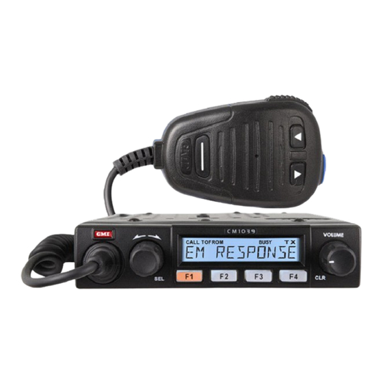
PRIMARY CONTROLS Front Panel Channel / Microphone On/Off Volume / Select Knob Display Socket Clear Knob F1 Function F2 Function F3 Function F4 Function Key Key Key Key Rear Panel 12V DC Connection Antenna Extension Socket Speaker MC513BC Microphone Call Key Push‐To‐Talk ... -
Page 8: Programmable Keys
PROGRAMMABLE KEYS The functions of the following buttons are determined through dealer programming. • Select (SEL) knob) • Clear (CLR) knob ) • F1 Key • F2 Key • F3 Key • F4 Key • Call Key (MC513BC top) • Dash ( ‐ ) Key (MC513BC front) MENU NAVIGATION The menu is used to adjust settings within the radio. Menu items can be individually enabled or disabled by the dealer programmer. Depending on how it is programmed, the menu in your radio may only include a small selection of the possible items listed below or it may be disabled completely. An enabled menu item may not be applicable to all installed channels; however, the menu item will always remain visible in the menu. Attempts to select the invalid menu item will result in an error beep. Menu Navigation ‐ General To access the menu, press the SEL knob. Rotate the SEL knob to scroll through the available menu options. Press the SEL knob again to select the displayed option. For submenu items, rotate the SEL knob again until the required submenu item is displayed then press the knob to select. Example: To adjust the Beep Tone volume level; 1. Press SEL to access the Menu. 2. Rotate to ‘SETTINGS’ then press SEL. 3. -
Page 9: Menu Map
Note: The Menu option will timeout after 5 seconds if no further menu selections are made. Menu Map The following Menu Map represents all of the available menu options. Only the menu items that have been enabled in your radio will actually appear in your radio’s menu. 9 ... -
Page 10: General Operation
GENERAL OPERATION BACKLIGHT The LCD back light brightness level is adjustable in 16 steps from off to full. To adjust the back light brightness; 1. Press SEL. 2. Rotate to ‘SETTINGS’ and press SEL. 3. Rotate to ‘DISPLAY’ and press SEL. 4. Rotate to ‘BKLGT’ and press SEL. 5. Rotate to select the required brightness setting. 6. Press SEL to accept. TX POWER LEVEL Sets the global maximum transmit power for the radio. The user can select from 1 of 4 levels: 1W, 5W, 10W, 25W. Note: Individual channels can also have their own power settings in which case the transmit power for the selected channel will be the lower of the two power settings. E.g. If a channel is set for 10W and the maximum power level is 25W, then the transmit power on that channel will be 10W. However if the maximum power is then lowered to 5W, then the actual transmit power on that channel will be 5W. To set the TX Power; 1. Press SEL. 2. Rotate to ‘SETTINGS’ and press SEL. 3. Rotate to ‘FUNCTIONS’ and press SEL. 4. Rotate to ‘TX POWER’ and press SEL. 5. Rotate to select the required TX power 6. Press SEL to accept. SQUELCH ... -
Page 11: Squelch Level
5. Rotate to select ON or OFF. The squelch will open when OFF is selected and close when ON is selected. 6. Press SEL to accept. Note: Squelch settings are not applicable to P25 operation. SQUELCH LEVEL The squelch level adjusts the sensitivity of the squelch to incoming signals. The squelch level should be set at a point where the squelch remains closed when there are no signals present but will open on most signals. In quiet country or rural locations where there is little interference a lower value may be set to allow the squelch to open on very weak signals. In inner city applications or areas of severe interference a higher value may be necessary to allow only stronger signals to open the squelch. To adjust the squelch level; 1. Press SEL. 2. Rotate to ‘SETTINGS’ and press SEL. 3. Rotate to ‘FUNCTIONS’ and press SEL. 4. Rotate to ‘SQL LEVEL’ and press SEL. 5. Rotate to select the required squelch level from 1 ‐ 9 6. Press SEL to accept. BEEP VOLUME The Beep Volume adjusts the volume level of the beeps that are heard when buttons are pressed. To adjust the Beep Volume; 1. Press SEL. 2. Rotate to ‘SETTINGS’ and press SEL. 3. Rotate to ‘ALERT LEVEL’ and press SEL. 4. -
Page 12: Firmware Version
FIRMWARE VERSION To read the current firmware version; 1. Press SEL. 2. Rotate to ‘SETTINGS’ and press SEL. 3. Rotate to ‘RADIO INFO’ and press SEL. 4. Rotate to ‘VERSION’ and press SEL. 5. The current radio firmware version will be displayed. 6. Press and hold CLR to exit the menu. ELECTRONIC SERIAL NUMBER (ESN) To view the radio’s electronic serial number; 1. Press SEL. 2. Rotate to ‘SETTINGS’ and press SEL. 3. Rotate to ‘RADIO INFO’ and press SEL. 4. Rotate to ‘SERIAL NO and press SEL. 5. The radio’s electronic serial number will be displayed. 6. Press and hold CLR to exit the menu. SELECTIVE CALL Selective Calling (Selcall) is a secure signaling system allowing individual radios to be selectively called without disturbing others on the same channel. Each radio can be pre‐ programmed with a unique Selcall Ident. The radio can then be set to remain totally quiet while it monitors the channel for Selcall signals. If an incoming signal contains a Selcall matching the Ident in your radio, an alarm sounds to alert you and the caller’s identification is displayed on your radio. In this way, even if you are away from your radio when the call is received, you will still know that you were called. You can then return the call at your convenience. If further calls are received, the most recent caller is displayed. If Selcall has been enabled on your radio, it may allow you to call others who are also using the Selcall system. It may also be programmed to allowing specific groups of radios to be ... -
Page 13: Dtmf
If the call is received successfully, a confirmation message will be displayed. Operating in the Quiet mode The QUIET mode prevents any incoming transmissions from being heard until your Selcall Ident is received. This allows you to monitor a busy channel for calls without being disturbed by unwanted signals. When your Selcall Ident is received, the QUIET mode is cancelled and all incoming signals will be heard in the speaker. If your radio is programmed with a Quiet key, you may be able to manually activate your radios Quiet muting system. If not, your radio's quiet muting system will have been preset for you by your retailer. DTMF Your radio may be fitted with DTMF ‘speed dial’ memories to provide pre‐programmed DTMF sequences. If fitted, DTMF ‘speed dial’ memories can be programmed into one of more of the function keys F1, F2, F3 or F4. MDC1200 DIGITAL DATA SIGNALLING MDC1200 digital / data signaling offers expanded calling functions. MDC1200 Menu functions are located in the SERVICES menu. Available menu options are; • Call Alert • Radio Check • Status • Status Request • Message • Remote Monitor • Stun • Revive MDC1200 – Primary use functions: • PTT‐ID • Emergency Call CTCSS/DCS (Continuous Tone Coded Squelch System / Digitally Coded Squelch) ... -
Page 14: Monitor Function
MONITOR A monitor key is used to monitor (listen) to a channel that would normally remain squelched (quiet) under the control of a CTCSS or DCS tone. When CTCSS/DCS is being used, there may be other users talking on the channel but you will not be able to hear anything. Pressing the Monitor key overrides the tone squelch to allow you to hear these signals. The Monitor key is often used to check that the channel is clear before transmitting. Note: The Monitor key does not open the Squelch; it simply overrides the CTCSS/DCS tone decoder. If there are no signals on the channel, the radio will still remain quiet and no receiver noise will be heard. ZONES The CM1039 series radio is capable of 50 zones which are used for allocating discreet channels or talk group (P25) into zones. Zones can also be used for regional, hierarchy or geographic grouping A zone is a collection of channels or talk groups. Zones are used to group channels that have something in common, such as public agency (police, fire, ambulance) or geographic region. When zones are enabled, the user can select channels only from the currently active zone. If zones are not required, zones can be globally disabled. All channels then appear in one list. The maximum channel capacity is 1072 channels. If zones are enabled, every channel must belong to a zone and each channel can be in only one zone at a time. Each zone can be individually enabled. A zone containing no channels is always disabled. When selecting a zone, the user can select only from the list of enabled zones. The maximum number of zones is 50. Selecting a zone To select a zone: 1. Press SEL to access the Menu. 2. Rotate the SEL knob to select ‘ZONES’ then press SEL. 3. Rotate the SEL knob to select the desired Zone then press SEL. ... - Page 15 channel in the current zone. The radio doesn't change to the selected zone until the SEL knob is pressed. If the CLR knob pressed, the zone menu clears and the radio continues to operate on the current channel. Programmable keys can be assigned to the ZONE function providing direct access to the ZONEs menu. The zone is then selected using the SEL knob. If zones are globally disabled, the zone menu item is also disabled. Zone Initial Channel By default, the radio changes to the first channel in the selected zone. The first channel is known as the home channel of the zone. Optionally the radio can be configured to save the current channel in the current zone before changing to the selected zone. The radio then changes to the saved channel of the selected zone. If there is no saved channel in the selected zone, the radio defaults to the first channel in the zone. Zone Display Each zone has a zone name. The zone name is displayed when selecting a zone using the ZONE menu. With a one‐line display it is not possible to show the channel name and zone name at the same time. The main screen normally displays the channel name. If a key is assigned to the ZONE function, then pressing that key will display the current zone. The radio changes to the zone select menu with the current zone as the starting point. Pressing the ZONE key again or pressing the BACK key cancels the zone select menu. If no key is pressed, a timeout will clear the zone menu and return the radio to the main screen. By this mean the user can check what the current zone is by a key press at any time, but the zone name is not normally displayed. Zones and Recall Channels A recall channel is a channel assigned to a RECALL key. The channel assigned to a RECALL key is not necessarily in the current zone. When the RECALL key is pressed, the radio changes to the recall channel. By default the radio changes to the zone the recall channel is in, (although this is optional), therefore the next channel change using the SEL knob will be from the recall channel's zone. Alternatively the radio can be configured to remain in the current zone while on the recall channel frequency or talk group. In this case the next channel change using the SEL knob will be from channels in the current zone. 15 ...
- Page 16 Zones and Scanning There are two main types of scanning; scan groups and zone scan. The scan behavior when zones are changed depends on the current scan type in progress. A scan group is a list of channels used for scanning or voting. The scan group appears in the channel list, and is selected by the user with the SEL knob. If the radio is currently on a scan group channel, scanning stops when the zone is changed. If the initial channel in the selected zone is a scan group, then scanning resumes with that scan group. Zone scan gives the user the ability to scan selected channels in the current zone. Channels to be included in the scan are tagged. Zone scan is started and stopped with the SCAN key. If zone scan is active when zones are changed then zone scan continues to be active in the selected zone if that zone has channels tagged for zone scan. If zone scan is not possible in the selected zone, (e.g. there are insufficient tagged channels) then scan stops and the radio changes to the initial channel in the zone. Channels in a scan group are not necessarily from the current zone. While scanning the radio remains in the current zone as it changes channels in the scan group. If a signal is received or PTT is pressed so the radio holds on a channel in the scan group, the radio remains in the current zone. If the user exits scan while holding on a channel in the scan group the radio may change to the zone of the hold channel or optionally remain in the current zone. Zone Editing Zones can be created, modified and deleted using the Radio programmer only. Zones cannot be modified by the user. If zones are enabled, there must be at least one zone in the radio. If there is only one zone, then all channels in the radio will be in that zone. A zone must contain at least one channel for that zone to be enabled. If no zone name is specified the radio generates a zone name: ZONE 1, ZONE 2 etc. A zone can be disabled with the radio programmer. A disabled zone cannot be selected by the user in the radio, however, the zone and its channels will still exist in the memory. A zone is deleted when all channels in that zone are also deleted or moved from that zone. If the zone contains channels that are members of a scan group that is in another zone, then 16 ...
-
Page 17: Scan
the zone cannot be deleted until the channel is removed from the scan group. When a zone is deleted, the zone name is erased and all zone flags are cleared. Every channel has to belong to a zone. Channels can be moved from one zone to another in the programmer. SCAN The scan feature is used to monitor a group of channels for activity. When there is activity on a channel the radio stops scanning and holds on that channel. A scan group can only contain Analog or P25 channels. The scan group cannot include another scan group or a P25 Trunking channel. The channels in the scan group do not have to be from the same zone as the scan group. Channels in the scan group may be hidden channels, or channels that can normally be selected. A scan group can contain up to 32 channels. There are two ways that channels can be grouped for scanning or voting: Scan Group Zone Scan Scan Group A scan group is a list of channels used for scanning or voting. The main use for a scan group is to define a channel that performs RSSI voting of repeater frequencies. However, scan groups can be configured for different types of scanning or voting. A scan group appears in the channel list and is selected using the SEL knob. The name of the scan group appears as a channel name; therefore a scan group appears to be another channel to the user. If zones are enabled, a scan group has to belong to a zone. A scan group can only belong to one zone. Several scan groups can be included in one zone. Scanning or voting begins automatically when the scan group is selected. Scanning or voting stops when the scan group is deselected. While there is no channel activity and the scan group is scanning, the scan group name is displayed. When channel activity is detected, the display may show the name of the channel the radio is holding on. When channel activity ceases and the radio resumes scanning or voting, the scan group name is displayed again. A scan group can be assigned to a RECALL key. When the RECALL is pressed while on another channel, the radio selects the scan group and scanning or voting begins immediately. If a RECALL key assigned to another channel or scan group is pressed while a 17 ... -
Page 18: Voting
scan group is active, then the scan group is deselected and scanning or voting stops. The radio then selects the channel or scan group assigned the RECALL key. A scan group is configured using the radio programmer. The scan group configuration cannot be modified and channels cannot be added to or removed from the scan group by the user. A scan group can be configured for either scanning or voting. Each scan group can be configured individually. Scanning Scanning is generally used to monitor a group of unrelated channels for activity. The radio checks each channel in the scan group in turn for activity and holds on the first channel with a valid signal. The conditions to hold on a channel are the same as the general un‐mute conditions of the radio. When the signal disappears the radio continues to hold on the channel until the scan hold timeout expires. If the scan hold timeout expires, the radio resumes scanning. Open Scan In Open Scan, the radio scans the channels in the sequence of the channel list checking for activity. If the PTT is pressed while holding on a channel, the radio transmits on the hold channel and the scan transmit channel is set to the hold channel. When the PTT is pressed while scanning, the radio transmits on the scan transmit channel. Priority Scan In Priority Scan, the radio scans the channels in sequence similar to open scan but checks a priority channel more often than the other channels. The first channel in the scan group is the priority channel. If the PTT is pressed while holding on a channel, the radio transmits on the hold channel. When the PTT is pressed while scanning, the radio transmits on the priority channel. VOTING Voting is generally used to monitor a group of channels associated with a repeater network. There are two general types of voting, RSSI voting and Busy Voting. RSSI Voting RSSI voting (also called Signal Strength voting) is used with repeater networks where the repeaters transmit the same information simultaneously on different repeater frequencies. 18 ... - Page 19 The radio scans the repeater output frequencies and selects the channel with the highest signal strength or the first channel above a signal strength threshold. The radio maintains a channel to use for PTT. Generally this is the last channel the radio selected for receive. If no signal has been received the radio will cycle through all the channels in turn on each PTT press. Busy Voting Busy voting is used when there are several repeaters on the same site providing a pool of channels to several groups of users. Each group of users is generally defined by a common CTCSS tone. The radio scans the channels and keeps track of which channels are free and which are busy and currently used by another group. When a signal is received with the correct CTCSS tone, the radio stops scanning and holds on that channel. When the PTT is pressed the radio transmits on a free repeater channel. The radios in a group don't transmit on the same repeater channel each time, as it depends on which repeater channel is in use at any given time. Zone Scan Zone scan is used to scan a group of channels for activity within the current zone. The channels are scanned in sequence for activity using open scan or priority scan methods. Voting is not used for zone scan. The channels to be scanned are tagged for zone scan. Analog channels, P25 Conventional channels, and scan groups can be tagged for zone scan. If a scan group is tagged, then only the first channel in the scan group is included in the zone scan sequence. P25 Trunking channels cannot be tagged. Hidden channels can also be tagged. Hidden channels can only be tagged by the radio programmer, not by the user. Zone scan channels are tagged using the radio programmer. The user may also optionally be enabled to tag channels for zone scan. To tag a channel, the user selects the channel with the SEL knob then tags the channel with a long press of the SCAN key. A tagged channel is untagged with a long press of the SCAN key. Zone scan is selected using the SCAN key. When the SCAN key is pressed, the radio commences scanning all the tagged channels in the current zone. The SCAN key is pressed again to stop zone scan. While zone scan is active the SEL knob cannot be used to select channels. If a RECALL key is pressed during zone scan, then zone scan stops and the radio selects the channel or scan group assigned to the RECALL key. 19 ...
-
Page 20: Scan Nuisance Delete
If a different zone is selected while zone scan is active, then zone scan continues to be active in the selected zone if possible. If there are not enough channels tagged for zone scan in the selected zone, then zone scan stops. If the SCAN key is pressed while a scan group is selected (i.e.: an RSSI voting channel), the radio stops the scan group activity and commences the zone scan. When the SCAN key is pressed again, the zone scan stops and the radio will resume scan group activity. During zone scan, the display changes through the zone scan channels. When activity is detected on a channel, the radio holds on the channel and the display shows the name of the hold channel. The current channel may be included in the zone scan channel list even if it is not tagged. SCAN NUISANCE DELETE A nuisance channel is one where temporary unwanted noise or interference constantly stops the scan. A nuisance channel can be temporarily removed by turning the SEL knob while holding on the channel. The radio will resume scanning and the nuisance channel will be removed for a fixed time (typically 2 minutes). A nuisance channel can also be removed from the scan sequence by a long pres of the SCAN key while holding on the channel. The radio will resume scanning and the nuisance channel will be removed as long as zone scan is active. DYNAMIC REGROUPING Dynamic regrouping allows the network or dispatcher to re‐assign the radio to a special communications talk group. When operating on this group, normal channel change operation may be disabled. Dynamic regrouping is only available on P25 trunking channels. To activate dynamic regrouping, the operator sends a ‘Dynamic Regroup Request’ to the P25 network. To send a Dynamic Regroup request: 1. Press the SEL knob to access the menu. 2. Rotate the SEL knob to select ‘TRUNKING’ then press the SEL knob. 3. Rotate the SEL knob to select ‘DYN REGROUP’ then press the SEL knob to send the request. 4. The display will show ‘SEND REQ’. If the request is successful the display shows an acknowledgement. The request may not succeed for various reasons. 20 ... -
Page 21: Failsoft Operation
Dynamic regrouping is de‐activated by either selecting another talk group/channel (if possible), or by send a request to de‐activate dynamic regrouping. When deactivated, the radio will return to the talk group that was active when the dynamic regroup request was sent. Dynamic regrouping is not preserved between power off‐on. FAILSOFT OPERATION If the radio is unable to access the trunking system, it can be programmed to enter failsoft mode. In failsoft mode the radio switches to a programmed conventional P25 or analog channel. Failsoft mode is entered when either a trunking channel is selected and the radio fails to register with the trunking controller, or the radio loses communications with the trunking controller. INSTALLATION The CM1039 is supplied with a slim, slide‐on mounting cradle. The cradle can be screwed or bolted in any convenient location in your vehicle (under or above the dash, on the centre console, etc) using the mounting slots provided in the base. The CM1039 contains a built‐in speaker and can be installed with the speaker facing upwards or downwards to ensure the receiver audio is projected clearly. Alternatively, the CM1039 can be fitted with an extension speaker if required. When installing the radio, avoid mounting it close to heaters or air conditioners. Screw the mounting cradle to a firm surface. Slide the CM1039 into the cradle from the front until it clicks into place. Finally, plug the power and antenna leads to the sockets provided on the rear of the radio. Mounting the Cradle 21 ... -
Page 22: Fitting The Radio
Fitting the Radio Removing the Radio Gently spread tabs Gently spread Slide radio from tabs cradle Fitting MC513BC Microphone Screw the microphone mounting clip to a firm surface. The microphone uses a miniature 6 pin telephone style plug and socket. To fit the microphone: 1. Position the microphone plug so the plastic tab faces downwards. Press the plug into the socket until it ‘clicks’. 2. Gently press the rubber strain relief into the hole surrounding the socket so that the slot around the strain relief fits neatly inside the lip of the hole. 22 ... -
Page 23: Removing The Microphone
Removing the microphone 1. Squeeze the rubber strain relief near the front panel to disengage the slot, and slide the strain relief back along the microphone cord. 2. Squeeze the plastic tab on the microphone plug towards the plug to unlock it while gently pulling the plug outwards. If the plug does not come out easily, the tab has not released correctly and should be squeezed again. Console Mounting the CM1039 Series For console mounting, a flush mounting DIN Adaptor MBD001 is available as an optional accessory. The adaptor includes mounting brackets and a specially designed front panel escutcheon to suit most vehicle installations. Installation instructions are provided with the bracket. See your nearest GME retailer for details. Din Adaptor MBD001 23 ... -
Page 24: Dc Power Connection
DC POWER CONECTION The CM1039 is designed for 13.8 Volt DC, negative earth installations only (i.e. where the negative terminal of the battery is connected to the chassis or frame of the vehicle). Two in‐line 10 Amp fuses are supplied. These fuses are to be connected as close to the battery as possible. The radio’s positive (red) lead should be connected via a 10 Amp fuse directly to the battery’s positive terminal. Connect the radio’s negative (black) lead via a 10 Amp fuse directly to the battery’s negative terminal. ANTENNA INSTALLATION To comply with FCC exposure limits the radio must be installed using an externally mounted antenna with a gain of either 2.15 dBi or 5.15 dBi. For best results your antenna should be professionally installed using industry standard techniques. Transmit only when bystanders are at a minimum safe distance of 35 inches (0.9 m) from the antenna. 24 ... -
Page 25: Specifications
SPECIFICATIONS GENERAL RF Performance: Compliant with AS/NZS 4295, ETSI EN 300-086-2, ETSI EN 300-113-2, TIA-603-C, FCC Parts 90/15, IC - RSS119 Frequency Band: VHF 136 to 174 MHz, UHF Lo 403 to 470 MHz, UHF Hi 450 to 512 MHz RF Switching Bandwidth: VHF 38 MHz, UHF 70 MHz Number of channels:... -
Page 26: Warranty
The Warranty period begins on the date of purchase from an authorized GME Sales and Service Outlet. This warranty is offered to the original end user and is not assignable or transferable. GME is not responsible for any ancillary equipment attached to or used in conjunction with its products.
Need help?
Do you have a question about the CM1039 and is the answer not in the manual?
Questions and answers