
Related Manuals for Captron CANEO 40 Puck Series


Summary of Contents for Captron CANEO 40 Puck Series
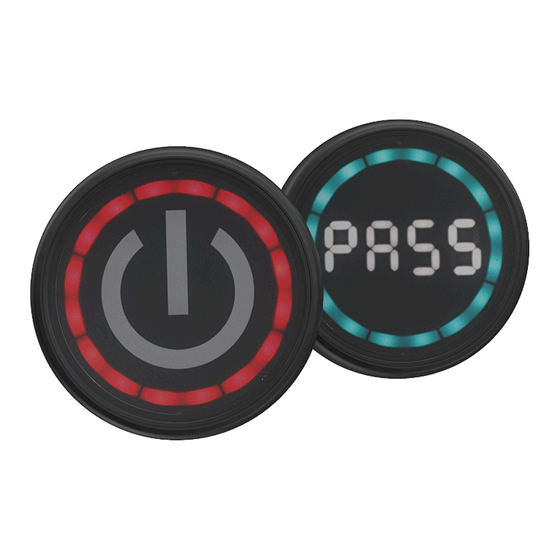
- Page 1 CANEO CANEO Original operating instructions Original operating instructions series40 Puck series40 Puck series40 Puck display series40 Puck display...
-
Page 2: Table Of Contents
Table of Contents 1 Foreword..................3 2 Safety.....................3 General safety................3 Notes and symbols used............3 Personnel qualifications............5 Intended use................5 Reasonably foreseeable misuse..........5 3 General description..............5 4 Assembly..................6 5 Operation..................7 6 Maintenance..................7 Maintenance operations............7 7 series40 disassembly..............7 8 Disposal..................8 9 Technical specifications.............. -
Page 3: Foreword
Foreword These operating instructions are intended for technicians/installers and operators and should be kept for future reference. Read these operating instructions carefully and make sure that you have fully understood the contents before installing or working with the SENSORswitches. Metric and imperial measurements are used in drawings. Imperial measurements are marked with [ ]. - Page 4 WARNING Warning designates a hazardous situation, which, if ignored, may lead to death or serious injury. The symbol next to the warning indicates the type and source of the danger. CAUTION Caution designates a hazardous situation, which, if ignored, may lead to injury.
-
Page 5: Personnel Qualifications
Personnel qualifications A qualified electrician is a person with suitable technical training, expertise and experience as well as knowledge of relevant standards, who can evaluate the work assigned to them correspondingly and recognize potential risks. Intended use The SENSORswitch is intended for use in accordance with the items listed here, the values from the “Technical specifications”... -
Page 6: Assembly
A SENSORswitch B Flat seal (fitted) C Lock nut D Connection M12 Assembly WARNING Improper work on electrical systems! Electric shock can result in death or life-threatening injuries. Before working on electrical systems, disconnect them from their voltage supply and secure them against being switched on again. Work on electrical installations should be carried out only by qualified personnel in compliance with local and national electrical regulations and specifications. -
Page 7: Operation
Operation series40 is operated by touching the button surface. For information on configuring the SENSORswitch, see our website series4x scan the QR code. Maintenance Maintenance operations Carry out the following maintenance operations at the specified intervals. Maintenance operation as needed annually Clean the button surface Check cables for intactness and firm fit... -
Page 8: Disposal
Disposal Different types of electrical and electronic components must be recycled according to their type. All applicable statutory, state and local laws and regulations must be complied with. Technical specifications series4x Operating voltage DC 12 - 24 V (8.4 to 31.2 V) Load current max. -
Page 9: Connection Options
Connection options Plug M12, 3-pin Plug M12, 4-pin Plug M12, 5-pin Connection plan 3-pin brown +VDC black IO - Link Communication (NPN / PNP NO / NC) blue The product description will indicate the configuration. CANEO 9/16 series40 Puck series40 Puck display... - Page 10 4-pin white brown +VDC black IO - Link Communication (NPN / PNP NO / NC) blue The product description will indicate the configuration. 5-pin white gray brown +VDC black IO-Link communication (NPN / PNP NO / NC) blue The product description will indicate the configuration. 10/16 CANEO series40 Puck...
-
Page 11: Drilling Pattern
Drilling pattern 20,4 The SENSORswitch is secured against rotation by the illustrated hole. Metric and imperial measurements are used in drawings. Imperial measurements are marked with [ ]. Dimensional drawing 26,5 13,1 2,68 1,04 0,52 M12x1 M22x1 CANEO 11/16 series40 Puck series40 Puck display... - Page 12 12/16 CANEO series40 Puck series40 Puck display...
-
Page 13: Manual Updates
Manual updates CAPTRON reserves the right to make changes to the contents of this manual as needed. The most current version can be found on our website www.captron.com Imprint The operating instructions have been authored and published by CAPTRON Electronic GmbH Johann-G.-Gutenberg-Straße 7... - Page 14 14/16 CANEO series40 Puck series40 Puck display...
- Page 15 CANEO 15/16 series40 Puck series40 Puck display...
- Page 16 Artikelbeschreibung / Product description 16/16 CANEO series40 Puck series40 Puck display...
Need help?
Do you have a question about the CANEO 40 Puck Series and is the answer not in the manual?
Questions and answers