
Related Manuals for jcb 19C-1e


Summary of Contents for jcb 19C-1e
- Page 1 OPERATOR'S MANUAL COMPACT EXCAVATOR 19C-1e EN - 9831/8250 ISSUE 4 - 09/2020 THIS MANUAL SHOULD ALWAYS STAY WITH THE MACHINE...
- Page 3 Operator's Manual. You must understand and follow the instructions in the Operator's Manual. If you do not understand anything, ask your employer or JCB dealer to explain it. OPERATOR'S Do not operate the machine without an Operator's...
- Page 4 Notes: 9831/8250-4...
-
Page 5: Table Of Contents
Table of Contents Contents Page No. Acronyms Glossary ............................Introduction About this Manual Model and Serial Number ........................1 Using the Manual ..........................1 Left-Hand Side, Right-Hand Side ......................1 Cab/Canopy ............................1 Cross References ..........................2 Location of Manual ..........................2 Safety Safety - Yours and Others ........................ - Page 6 Table of Contents Entering and Leaving the Operator Station General ..............................28 Service Disconnect General ..............................30 Before Starting the Machine General ..............................31 Operator Seat General ..............................32 Basic Seat ............................32 Suspension Seat ..........................33 Seat Belt General ..............................34 Inertia Reel Seat Belt .........................
- Page 7 Table of Contents Load Charts ............................60 Overload Warning System ........................61 Working with the Excavator End General ..............................62 Preparing to Use the Excavator End ....................62 Lifting With the Excavator End ......................62 Digging ..............................64 Working with the Dozer Blade General ..............................
- Page 8 Put into Storage ..........................104 During Storage ..........................104 Take out of Storage .......................... 105 Security General .............................. 106 JCB Plantguard ..........................106 Construction Equipment Security and Registration Scheme (CESAR) ..........106 Maintenance Introduction General .............................. 107 Owner/Operator Support ........................107 Service/Maintenance Agreements ....................
- Page 9 Table of Contents Seat Belt ............................132 Controls ............................. 133 Tracks General ............................. 134 Rubber .............................. 134 Track Gearbox Oil ..............................137 Hydraulic System General ............................. 138 Services ............................139 Oil ..............................140 Cylinders / Rams ..........................140 Electrical System General .............................
-
Page 10: Acronyms Glossary
Table of Contents Acronyms Glossary Alternating Current CESAR Construction Equipment Security and Registration Direct Current Electronic Control Unit FOGS Falling Object Guard System FOPS Falling Object Protective Structure HBCV Hose Burst Check Valve Hydraulic Tool Carrier International Organization for Standardization Light Emitting Diode MECU Machine Electronic Control Unit... -
Page 11: Introduction
Particular attention must be given to all the safety aspects of operating and maintaining the machine. If there is anything you are not sure about, ask your JCB dealer or employer. Do not guess, you or others could be killed or seriously injured. -
Page 12: Cross References
Introduction About this Manual Cross References In this manual, cross references are made by presenting the subject title in blue (electronic copy only). The number of the page upon which the subject begins is indicated within the brackets. For example: Refer to: Cross References (Page 2). -
Page 13: Safety
If you do not fully understand the warning messages, ask your employer or JCB dealer to explain them. Safety is not just a matter of responding to the warnings. All the time you are working on or with the machine you must be thinking of what hazards there might be and how to avoid them. -
Page 14: General Safety
Machine Modifications This machine is manufactured in compliance with prevailing legislative requirements. It must not be altered in any way which could affect or invalidate its compliance. For advice consult your JCB dealer. Clothing and Personal Protective Equipment (PPE) Do not wear loose clothing or jewellery that can get caught on controls or moving parts. Wear protective clothing and personal safety equipment issued or called for by the job conditions, local regulations or as specified by your employer. -
Page 15: About The Product
Product Compliance Your JCB product was designed to comply with the laws and regulations applicable at the time of its manufacture for the market in which it was first sold. In many markets, laws and regulations exist that require the owner to maintain the product at a level of compliance relevant to the product when first produced. -
Page 16: Description
For more information, contact your JCB dealer. Optional Equipment and Attachments A wide range of optional attachments are available to increase the versatility of your machine. Only the JCB approved attachments are recommended for use with your machine. Contact your JCB dealer for the full list of approved attachments available. -
Page 17: Main Component Locations
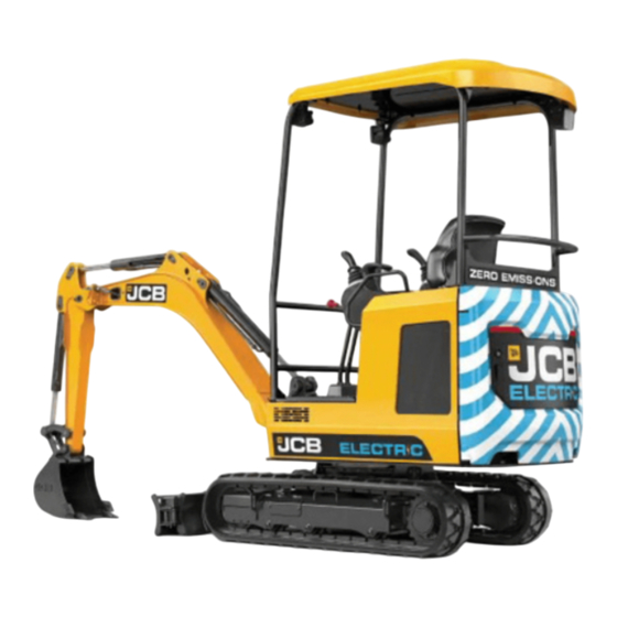
About the Product Description Before you do a maintenance task, make the product safe. Main Component Locations Figure 4. A Canopy (contains the operator station) B Upper structure C Undercarriage D Dozer blade E Kingpost F Bucket G Boom (part of the excavator arm) H Dipper (part of the excavator arm) 9831/8250-4... -
Page 18: Product And Component Identification
This must be done by a qualified person. For assistance, contact your JCB dealer. Failure to take precautions could result in death or injury to the operator. - Page 19 Product and Component Identification WARNING When replacing or repairing the ROPS/FOGS/TOPS structure you must replace the fixings. Never re-use fixings. Use only new genuine JCB fixings tightened to the torque figures specified in the operator's manual. ROPS and TOPS Data Plate Machines built to the ROPS (Roll-Over Protective Structure) and TOPS (Tip-Over Protective Structure) standards have an identification label attached to the cab/canopy.
- Page 20 About the Product Product and Component Identification Figure 6. A FOGS data plate B ROPS and TOPS data plate 9831/8250-4...
-
Page 21: Safety Labels
Keep all of the safety labels clean and readable. Replace a lost or damaged safety label. Make sure the replacement parts include the safety labels where necessary. Each safety label has a part number printed on it, use this number to order a new safety label from your JCB dealer. 9831/8250-4... -
Page 22: Safety Label Identification
About the Product Safety Labels Safety Label Identification Figure 7. 817/7006-2 332/V3761-1 332/T9356-2 817/70112 817/70018 817/700106-2 817/7004 9831/8250-4... - Page 23 About the Product Safety Labels Figure 8. 817/70112 817/700106-2 817/7004 Table 2. Safety Labels Item Part No. Description Qty. 332/F0279 Stability hazard. Ensure the load is within the capability of the machine. Read the Operator’s Manual. 817/70014 Warning. Read the Operator’s Manual before you operate the machine. 332/T9356 Falling hazard.
- Page 24 About the Product Safety Labels Item Part No. Description Qty. 817/70018 Warning. Crushing of whole body. Do not operate the controls from outside of the machine. 817/70106 Strike to whole body (machine swing). Keep a safe distance from the machine. 817/70004 Warning.
-
Page 25: Operator Station
About the Product Operator Station Operator Station Component Locations Figure 9. A Track controls Refer to: Track Controls B Control lever Refer to: Excavator End Controls (Page 45). (Page 53). C Track extension lever Refer to: Retractable D Dozer blade control lever/ 2-speed selection Undercarriage Controls (Page 57). - Page 26 About the Product Operator Station Q Quickhitch release bar- stowage position R Hourmeter 9831/8250-4...
-
Page 27: Interior Switches
About the Product Interior Switches Interior Switches Ignition Switch The ignition key operates the four-position ignition switch. The ignition key can only be inserted or removed in position 0. If the machine fails to start, the ignition key must be returned to position 0 before starting the motor again. Figure 10. -
Page 28: Console Switches
About the Product Console Switches Console Switches General Figure 11. Table 4. Control isolation solenoid on/ When the LED (Light Emitting Diode) is illuminated the hydraulics are off switch active. Aux1 selection switch Illuminates when single acting or double acting system is selected. Lift overload switch Illuminates when lift overload capacities is exceeded, remove the ex- cess load and press the switch to silence the buzzer. - Page 29 About the Product Console Switches Beacon on/off switch LED illumination: Beacon on Q-Hitch sequence switch Not used 9831/8250-4...
- Page 30 Notes: 9831/8250-4...
-
Page 31: Operation Introduction General
Operation Introduction Operation Introduction General The aim of this part of the manual is to guide the operator step-by-step through the task of learning how to operate the machine efficiently and safely. Read the Operation section through from beginning to end. The operator must always be aware of events happening in or around the machine. -
Page 32: Operating Safety
On a busy site, use a signalman. Before doing any job not covered in this manual, find out the correct procedure. Your local JCB distributor will be glad to advise you. - Page 33 Operation Operating Safety Electrical Power Cables You could be electrocuted or badly burned if you get the machine or its attachments too close to electrical power cables. You are strongly advised to make sure that the safety arrangements on site comply with the local laws and regulations concerning work near electric power lines.
-
Page 34: Worksite Safety
Operation Operating Safety Roll Over Protection If the machine starts to roll over, you can be crushed if you try to leave the cab. If the machine starts to roll over, do not try and jump from the cab. Stay in the cab, with your seat belt fastened. Confined Areas Pay extra attention to proximity hazards when operating in confined areas. -
Page 35: Risk Assessment
It is essential that a risk assessment of the work to be done is completed and that the operator obeys any safety precautions that the assessment identifies. If you are unsure of the suitability of the machine for a specific task, contact your JCB dealer who will be pleased to advise you. - Page 36 Operation Operating Safety • How steep are any slopes, up/down/across? A cross slope is particularly hazardous, is it possible to detour to avoid them? Weather • How windy is it? High wind will adversely affect the stability of a loaded machine, particularly if the load is bulky.
-
Page 37: Walk-Around Inspection
Operation Walk-Around Inspection Walk-Around Inspection General WARNING Walking or working under a raised boom and dipper is hazardous. You could be crushed by the boom and dipper or get caught in the linkages. Lower the boom and dipper before doing these checks. The following checks must be made each time you return to the machine after leaving it for any period of time. -
Page 38: Entering And Leaving The Operator Station
Operation Entering and Leaving the Operator Station Entering and Leaving the Operator Station General WARNING For safety reasons, machines installed with single access canopies from new must not have the barrier removed. The machine must always be entered/exited with the left hand console raised. WARNING Do not enter or exit the cab unless the left console lever is in the fully raised position. - Page 39 Operation Entering and Leaving the Operator Station Figure 13. A Handrails B Track C Cab step 3. Hold the left handrail, step into the cab and swing yourself into the operators seat. Leaving the canopy 1. Park the machine on solid, level ground with the upper structure parallel to the undercarriage. 2.
-
Page 40: Service Disconnect
This below procedure is applicable for the partial isolation of battery for working on the PDU (Power Distribution Unit), AC (Alternating Current)/DC (Direct Current) converter, inverter or motor. For full isolation of the battery system or junction box, contact your local JCB dealer. Disconnect the Machine Electrics 1. -
Page 41: Before Starting The Machine
3.5. Remove or stow all loose articles in the canopy, for example tools. 3.6. Examine the ROPS (Roll-Over Protective Structure) and TOPS (Tip-Over Protective Structure) for damage. Get your JCB dealer to repair any damage. Make sure all securing bolts are installed and correctly tightened. -
Page 42: Operator Seat
Operation Operator Seat Operator Seat General CAUTION Position the seat so that you can comfortably reach the machine controls. Do not adjust the seat while the machine is moving. You could have an accident if you operate the machine with the seat in the wrong position. -
Page 43: Suspension Seat
Operation Operator Seat Suspension Seat Mechanical Suspension Seat Figure 16. A Fowards/backwards adjustment lever B Weight adjustment lever C Seat tilt-back control lever 9831/8250-4... -
Page 44: Seat Belt
Operation Seat Belt Seat Belt General WARNING Operating the machine without a seat belt can be dangerous. Before starting the motor, make sure your seat belt is fastened. Check the tightness and condition of the seat belt securing bolts regularly. WARNING When a seat belt is installed on your machine replace it with a new one if it is damaged, if the fabric is worn, or if the machine has been in an accident. - Page 45 Operation Seat Belt Figure 18. C Seat belt D Button Release the Seat Belt WARNING Release the seat belt only after safely stopping the machine, switching off the motor and engaging the park brake (if applicable). 1. Push the button and pull the tongue from the latch. 2.
-
Page 46: Mirrors
Operation Mirrors Mirrors General Installation Introduction When they operate the machine, the operator must continually survey their field of vision. It is important that the mirrors are securely installed and give maximum vision around the machine. When a mirror is provided to supplement the operators direct field of vision, it must be adjusted to serve as an aid to the operator in seeing people or obstacles around the machine. - Page 47 Operation Mirrors Figure 20. 45° 45° A Field of vision 9831/8250-4...
-
Page 48: Starting The Machine
Operation Starting the Machine Starting the Machine General WARNING Thoroughly warm the hydraulic oil before operating the excavator services. Before selecting boom up, check there are no overhead obstructions or electric power cables. 1. Make sure that the machine is ready to start. Refer to: Immobiliser (Page 39). -
Page 49: Immobiliser
If your machine has an immobiliser system installed, then your JCB dealer should enable the system as part of the standard machine Installation. If you prefer that the system is not enabled, then you must tell your JCB dealer. Your JCB dealer can enable the system at a later date. Machines with immobilisers installed should always be parked as per the instructions in the operators manual. - Page 50 Operation Starting the Machine 6. If an incorrect PIN code is entered, both the ‘tick’ button and 'back' button will flash for the specified duration, the lock symbol on the instrument cluster will not disappear. Repeat step 2 to 5 Duration: 3s 7.
-
Page 51: Stopping And Parking
Operation Stopping and Parking Stopping and Parking General WARNING Make sure that the excavator is in a safe condition. CAUTION Low speed must always be selected when unloading the machine from a vehicle or tracking down steep slopes. The machine will take longer to stop when the levers are released if high speed is selected. 1. -
Page 52: Preparing For Travel
Operation Preparing for Travel Preparing for Travel General When you travel on the road or on site there are usually local rules and safety regulations for the machine travel position. This publication contains recommendations that may help you meet the requirements of these regulations, they are not necessarily the applied law. -
Page 53: Safety Equipment
Operation Safety Equipment Safety Equipment General When you travel on the road or on site there are usually local rules and safety regulations for the machine travel position. This publication contains recommendations that may help you meet the requirements of these regulations, they are not necessarily the applied law. - Page 54 Operation Safety Equipment Figure 24. A Hydraulic controls isolation lever B Left hand pod 9831/8250-4...
-
Page 55: Drive Controls
Operation Drive Controls Drive Controls Track Controls WARNING When the cab is swung around so that it is facing the track motor end of the undercarriage, the operation of the track controls is reversed. Take extra care! The tracks are controlled using the control levers in front of the operator seat. The left control lever controls the left track. - Page 56 Operation Drive Controls The throttle control can be left in any one of the three position (H, G, L ) as required. Instrument panel displays the current selected mode. Table 5. Mode Description Low output used for fine control applications. General output used for standard applications.
-
Page 57: Instruments
WARNING If there is a fault with the machine electrical system an error may be displayed on the instrument panel. Contact your JCB dealer. Do not try to repair it yourself. The gauges, warning and indicator lamps are grouped together on the instrument panel. When a warning lamp comes on, an alarm will sound. - Page 58 Illuminates green when SAE controls are active. motive Engineers) ac- tive Master warning Audible/Visual. If amber light Illuminates then contact JCB dealer. If red light Illuminates then stop the machine immediately and contact your JCB dealer. Quickhitch unlock Illuminates amber when quickhitch is unlock.
-
Page 59: Getting The Machine Moving
Operation Getting the Machine Moving Getting the Machine Moving General WARNING Do not dismount a moving machine. The machine does not have gears. Do not overwork the motor unnecessarily. Operate the motor at a speed suitable for the duty being carried out. When moving the machine, keep it under control at all times. -
Page 60: Slopes
Operation Slopes Slopes General WARNING Make sure that you have been trained and are familiar with the use of machines on slopes, and understand the adverse affects that slopes and site conditions can have on stability. Never use the machine on a slope if you do not understand the recommended practices for the use of machines in such applications. -
Page 61: Working On Slopes
Operation Slopes When traversing a slope, ensure the following travel position is adhered to: 1. Position the cab facing forward over the dozer. 2. Raise the dozer blade. 3. Lower the boom so that the bucket or attachment is clear of the ground as specified distance and dipper is placed at specified angle to the ground. -
Page 62: Driving The Machine
Operation Driving the Machine Driving the Machine General WARNING When the cab is swung around so that it is facing the track motor end of the undercarriage, the operation of the track controls is reversed. Take extra care! The track controls operate as described when the excavator is positioned with the track idlers at the front. If the excavator is positioned with the track idlers at the rear the lever operation will be reversed. -
Page 63: Operating Levers/Pedals
Operation Operating Levers/Pedals Operating Levers/Pedals General WARNING Make sure it is clear overhead before raising the boom. Keep an adequate safe distance from all electrical power lines. Contact your local power company for safety procedures. CAUTION Keep the machine controls clean and dry. Your hands and feet could slide off slippery controls. If that happens you could lose control of the machine. - Page 64 Operation Operating Levers/Pedals Horn Button The horn button is located on the right hand excavator lever. Refer to: Component Locations (Page 15). Press and hold the button to activate the horn. It functions only when the ignition switch is on. Excavator Controls The excavator controls consist of the excavator levers.
- Page 65 Operation Operating Levers/Pedals Excavator Levers (ISO Control Pattern) Figure 37. A Slew cab left B Slew cab right C Raise boom D Lower boom E Dipper in F Dipper out G Crowd bucket (to gather a load) H Dump bucket (to dump a load) 9831/8250-4...
-
Page 66: Dozer Blade Controls
Operation Operating Levers/Pedals Swing Figure 38. A Swing left B Swing right C Thumb wheel D Change over button Press the change over button on the left joystick to select swing mode. An icon is displayed on the instrument panel. Press the change over button on the left joystick to select swing mode. -
Page 67: Retractable Undercarriage Controls
Operation Operating Levers/Pedals Figure 39. A Lower the dozer B Raise the dozer C Control lever D 2-speed selection button Retractable Undercarriage Controls To extend or retract the undercarriage (option): 1. Stop the machine on level ground. 2. Make sure that all persons are away from the machine and the surrounding area. 3. -
Page 68: Auxiliary Circuit Controls
Operation Operating Levers/Pedals Figure 41. A Track extension lever B Upward- retract C Downward- extend Auxiliary Circuit Controls WARNING Before operating the auxiliary control system make sure that you are aware of all safety notices that apply to the attachment you are using. Also make sure you have installed the attachment correctly and have read its operator's manual. - Page 69 Operation Operating Levers/Pedals Figure 42. A Tilt/grab changeover for tilt-rotator B Boom swing/AUX changeover C Left thumb wheel control - AUX2 D Right finger button - hammer continuous flow E Right thumb wheel control- AUX1 or boom swing Tilt/grab changeover for tilt-rotator and right finger button for hammer continuous flow are located underside of joystick.
-
Page 70: Lifting And Loading
The owner and/or operator must make sure that they fully understand the laws and regulations concerning the use of the JCB machine as an earthmover and for lifting. Consult your JCB dealer for more information. In certain countries safety regulations in force call for the application of specific safety factors. Consult your JCB dealer for more information. -
Page 71: Overload Warning System
The relevant load chart for your machine contains a part number. If the chart is missing or damaged a new decal must be attached, contact your JCB dealer for advise if you are not sure. Refer to: Performance Dimensions (Page 151). -
Page 72: Working With The Excavator End
Operation Working with the Excavator End Working with the Excavator End General WARNING When using the boom and dipper fully extended, take the following precautions, otherwise the machine could get damaged or become unstable and become a danger to you and other people. Make sure you do not exceed the working capacity of the boom at maximum reach. - Page 73 Refer to: Excavator End Dimensions and Performance (Page 151). 3. The correct JCB lifting shackle must be fitted. The bucket ram must be fully extended. If your machine is not installed with this equipment there will be a decal in the operators cab and you must use the machine for earth moving purposes only.
-
Page 74: Digging
Operation Working with the Excavator End Digging General WARNING Do not use pedals which are not locked in position as foot rests. Notice: When carrying out deep digging it is advisable to have the upper structure swung in line with the chassis. - Page 75 Operation Working with the Excavator End Figure 48. 5. Start dumping as the bucket approaches the pile. Do not waste time by dumping too far from the excavation. Dump close to the start dig position. 6. Swing the bucket back to the excavation and start the next dig. Backfill the excavation by loading the bucket with soil from the pile.
-
Page 76: Working With The Dozer Blade
Operation Working with the Dozer Blade Working with the Dozer Blade General When you work with the dozer blade, remember that you will be driving the machine. Keep alert for bystanders, animals and possible hazards. When possible, do not slew the machine to do a dozer blade task. If you must slew the machine to do a dozer blade task, use a smooth slew action and make sure there are no obstacles. -
Page 77: Backfilling
Operation Working with the Dozer Blade Backfilling When you backfill on a slope, pile the material on the high side of the trench when possible. Move the dozer blade level to the ground. Work at right angles to the trench, fill a dozer blades width at a time. Leave any spillage until the trench is filled. -
Page 78: Power Sockets
Operation Power Sockets Power Sockets Auxiliary Power Socket Your machine may be installed with one or more 12V auxiliary power sockets, which can be used for mobile phone chargers or other 12V powered devices. Only connect items which are compatible with the power rating of the socket and have the correct plug. Always operate the machine during the prolonged use of the electrical accessories, or the battery can discharge. -
Page 79: Fire Extinguisher
Operation Fire Extinguisher Fire Extinguisher General Location The fire extinguisher is located behind the seat and is held in position by a stowage bracket. Refer to: Operator Station (Page 15). Keep the fire extinguisher in this position until you need to use it. Operation WARNING Do not use the fire extinguisher in a confined space. -
Page 80: Moving A Disabled Machine
You must contact your nearest JCB dealer before you try to tow, winch or push the machine. Towing, winching or pushing the machine without following the correct procedure will damage parts of the hydraulic system. -
Page 81: Excavator End (Emergency Operation)
Operation Moving a Disabled Machine Figure 56. Excavator End (Emergency Operation) The excavator has an accumulator installed in the hydraulic pilot control system. The accumulator stores a limited amount of hydraulic pressure for use in an emergency (motor failure for example). This hydraulic pressure must be used to move the dipper and lower the boom into a safe position. -
Page 82: Lifting The Machine
Operation Lifting the Machine Lifting the Machine General DANGER Do not stand underneath the raised load during the lifting/lowering procedure. Stand clear and to one side until the load has been safely lowered. Make sure that the area is clear of other people before lowering the load. - Page 83 Operation Lifting the Machine 7. Check that the lifting eye is positioned directly above the machine centre of gravity. Figure 58. A Boom lift point B Dozer blade lift point C Spreader bar D Centre of gravity E Dimension= 817mm F Dimension= 786mm G Dimension= 528mm 9831/8250-4...
-
Page 84: Transporting The Machine
Operation Transporting the Machine Transporting the Machine General WARNING The safe transit of the load is the responsibility of the transport contractor and driver. Any machine, attachments or parts that may move during transit must be adequately secured. WARNING Make sure that the ramp incline does not exceed the machine's operational limits. CAUTION Before moving the machine onto the trailer, make sure that the trailer and ramp are free from oil, grease and ice. - Page 85 Operation Transporting the Machine 5. With the machine in low speed mode, track forward onto the ramp slowly and smoothly. Make sure the bucket will not contact the transporter ramps when loading the machine. Figure 60. 6. Slowly drive the machine to the top of the ramps. 7.
- Page 86 Operation Transporting the Machine Figure 62. Method 1 A Front undercarriage track leg tie-down points B Rear undercarriage track leg tie-down points C Angle = 25° to 45° D Angle = 9° to 15° E Length = 1,723mm to 1,027mm F Length = 1,726mm to 1,023mm G Length = 2,500mm H Slew ring centre line...
- Page 87 Operation Transporting the Machine Figure 63. Method 2 A Front slew spine tie-down points B Rear slew spine tie-down points C Angle = 35° to 46° D Angle = 45° to 60° E Angle = 9° to 15° F Length = 2,499mm to 1,846mm G Length = 2,720mm to 1,943mm H Length = 2,500mm J Slew ring centre line...
- Page 88 Operation Transporting the Machine Figure 64. Method 3 A Front slew spine tie-down points B Rear undercarriage turret tie-down points C Angle = 35° to 46° D Angle = 35° to 45° E Angle = 9° to 15° F Length = 2,499mm to 1,846mm G Length = 2,282mm to 1,670mm H Length = 2,500mm J Slew ring centre line...
-
Page 89: Unloading The Machine From The Transporting Vehicle/Trailer
Operation Transporting the Machine Table 7. Lashing capacity 17,000N (Maximum) Unloading the Machine from the Transporting Vehicle/Trailer WARNING If the dozer blade is to the rear, the track controls will be reversed. Use extreme caution when tracking off the trailer. 1. -
Page 90: Operating Environment
Charging may be restricted in high and low ambient conditions. The recommended temperature range for charging is from -20°C (-4.0°F) to 46°C (114.7°F). Consult your local JCB dealer for more information. In high and low temperature conditions, take the following precautions. They will make it easier to start and prevent possible damage to your machine. -
Page 91: Attachments
Always check the instruction supplied with the attachment, or if in doubt check with a JCB Dealer for advice. Some specification limits may also be shown on the data/rating plate on the attachment. -
Page 92: Connecting/Disconnecting Hydraulic Hoses
980/B5211 HM012T- top mount 980/B0450 Quickhitch adaptor (auger) (1) Mechanical Quickhitch is compatible with JCB supplied old buckets. (2) Adaptor to connect earth drill to mechanical and hydraulic Quickhitch. (3) GP is abbreviation for General Purpose. Connecting/Disconnecting Hydraulic Hoses WARNING Fine jets of fluid at high pressure can penetrate the skin. Keep face and hands well clear of fluid under pressure and wear personal protective equipment. - Page 93 Attachments Working with Attachments Connecting the Hydraulic Hoses 1. Make the machine safe. Refer to: Maintenance Positions (Page 116). 2. Vent the hydraulic system. Refer to: Discharge (Page 138). 3. Check the hoses and adaptors for damage. Refer to: Check (Condition) (Page 139). 4.
- Page 94 Attachments Working with Attachments Figure 68. 5. Check for leaks: 5.1. Start the machine. 5.2. Operate the related controls to increase the pressure in the hydraulic system. 5.3. Stop the machine then remove the ignition key. 5.4. Check for indications of leakage at the hose connections. Correct, as necessary. Disconnecting the Hydraulic Hoses 1.
- Page 95 Attachments Working with Attachments Figure 69. A Female coupling B Male coupling The quick release couplings will be trouble free and relatively easy to connect and disconnect, if they are kept clean and used correctly. The recommendations listed below must always apply when using flat face quick release couplings.
-
Page 96: Impact Protection
Make sure that the attachment, for example a hydraulic breaker is positioned in front of the cab before it is operated. Do not slew the boom to the side during operation of the attachment. Consult your JCB dealer for further information. Figure 71. -
Page 97: Direct-Mounted Attachments
Attachments Direct-Mounted Attachments Direct-Mounted Attachments General WARNING If two people are doing this job make sure that the person working the controls is a competent operator. If the wrong control lever is moved, or if the controls are moved violently, the other person could be killed or injured. -
Page 98: Quickhitch
Attachments Quickhitch Quickhitch Excavator End Quickhitch General WARNING Always install the quickhitch latch hook locking pin (mechanical only). Failure to install the pin will result in possible failure of the latching mechanism. Such a failure could result in the sudden release of an attachment from the machine and you or others could be killed or seriously injured. - Page 99 Attachments Quickhitch Figure 73. A Hole (dipper arm) B Hole (bucket link) C Hole (quickhitch) D Pivot pin (quickhitch to dipper arm) E Pivot pin (quickhitch to bucket link) F Hex head bolt G Lock nut 5.1. Operate the controls to line up the hole in the bucket link with the hole in Quickhitch. 5.2.
- Page 100 Attachments Quickhitch Figure 74. A Front jaw B Front pivot pin 4. Raise the attachment from the ground and roll the Quickhitch in the direction of the arrow until the rear pivot pin is resting on the Quickhitch latch hook. 5.
- Page 101 Attachments Quickhitch Figure 75. C Rear jaw D Rear pivot pin E Quickhitch latch hook F Latch hook locking pin G Lynch pin H Tommy bar Mechanical Quickhitch Attachment Removal 1. Park the machine on firm level ground. 2. Position the attachment approximately the specified distance from the ground in the orientation shown. Refer to Figure 76.
- Page 102 Attachments Quickhitch Figure 77. F Latch hook locking pin G Lynch pin H Tommy bar 4. Insert the tommy bar into the hole of the latch hook as shown. WARNING! The attachment will move when released. Stand clear and to one side when releasing the attachment.
- Page 103 Attachments Quickhitch Figure 79. A Front pivot pin Hydraulic Hitch Unlock Sequence Standard Attachment 1. To start Quickhitch unlock process make sure that hydraulics are on then press the Quickhitch sequence switch. Figure 80. 2. Press the control isolation switch to confirm the process. Make sure that LED (Light Emitting Diode) on the boom turns red.
- Page 104 Attachments Quickhitch Figure 83. A Jaw B Attachment 5. To engage the lock on the Quickhitch press one of the two switches shown. 5.1. Check the hitch visually to confirm it is locked. Figure 84. Figure 85. Maintenance Check the operation of the Quickhitch daily. Examine the Quickhitch daily for broken or missing parts.
-
Page 105: Buckets
Attachments Buckets Buckets General WARNING The bucket selected must be the correct width to suit the hole/trench to be excavated. However, if the hole width demands a larger bucket, consideration must be given to the density/weight of the material to be moved affecting the stability of the machine especially if working on a slope. If there is danger of the machine's stability being compromised, then select a smaller bucket or reposition the machine. - Page 106 Attachments Buckets Installation 1. Put the tooth in position. 2. Install the nuts and bolts to secure the tooth in position. Toe Plate Removal 1. Make the machine safe. Refer to: Maintenance Position (Excavator End Lowered) (Page 116). 2. Remove the nut and bolt. 3.
- Page 107 Attachments Buckets Installation 1. Put the toe plate in position. 2. Install the nuts and bolts to secure the toe plate in position. 9831/8250-4...
-
Page 108: Rockbreaker
Attachments Rockbreaker Rockbreaker General WARNING If a second person is involved with the operation ensure that the machine controls are not operated whilst they are in the working envelope of the machine and attachment, otherwise the other person could be killed or injured if a control is moved accidentally. WARNING You or others can be killed or seriously injured if you do unfamiliar operations without first practising them. - Page 109 Attachments Rockbreaker 3. Position the rockbreaker horizontally onto the ground. Refer to Figure 89. Figure 89. 4. Make the machine safe. 4.1. Stop the machine. 4.2. Release the auxiliary pressure. Refer to: Discharge (Page 138). 4.3. Disconnect the battery to prevent accidental operation of the machine. 5.
- Page 110 Attachments Rockbreaker For hammer button. Refer to: Excavator End Controls (Page 53). For Aux1 button. Refer to: Console Switches (Page 18). 9831/8250-4...
-
Page 111: Preservation And Storage
Preservation and Storage Cleaning Preservation and Storage Cleaning General WARNING When using cleaning agents, solvents or other chemicals, you must adhere to the manufacturer's instructions and safety precautions. WARNING Airborne particles of light combustible material such as straw, grass, wood shavings, etc. must not be allowed to accumulate within the battery compartment. -
Page 112: Preparation
Preservation and Storage Cleaning • Keep water temperature below 80°C (175.9°F). • Use a spray nozzle with a 40° wide angle spray pattern. • Keep the nozzle at least 300mm away from and perpendicular (at 90° degrees) to the decal. The machine must always be greased (if appropriate) after pressure washing or steam cleaning. -
Page 113: Checking For Damage
Preservation and Storage Checking For Damage Checking For Damage General Refer to the individual condition checks throughout the Maintenance section. Refer to: Maintenance Schedules (Page 112). 9831/8250-4... -
Page 114: Storage
Preservation and Storage Storage Storage General If the machine will not be used for an extended period, you must store the machine correctly. If you prepare the machine carefully and apply on-going care you can prevent deterioration and damage to the machine while it is in storage. -
Page 115: Take Out Of Storage
Preservation and Storage Storage 3. Start the motor. 4. Operate the hydraulic controls. Make sure that the hydraulic functions operate correctly. 5. Prepare the machine for storage. Take out of Storage 1. Clean the machine to remove all unwanted material and corrosive products. Dry the machine to remove solvents and moisture. -
Page 116: Security
The Construction Equipment Association is managing the scheme, and Datatag are providing the security material and support. JCB is fully supportive of the CESAR initiative and will offer it as a factory option across the range. -
Page 117: Maintenance
JCB trained specialist competent person. JCB dealer service engineers have been trained by JCB to do such specialist tasks, and are equipped with the necessary special tools and test equipment to do such tasks, thoroughly, safely, accurately and efficiently. -
Page 118: Service/Maintenance Agreements
If you use non-genuine JCB parts or consumables, then you can compromise the health and safety of the operator and cause machine failure. A parts book for your machine is available from your JCB dealer. The parts book will help you identify parts and order them from your JCB dealer. -
Page 119: Maintenance Safety
Maintenance Maintenance Safety Maintenance Safety General Electrical Repairs The machine uses a 48V electrical system. The electrical cables carrying 48V are orange in colour. Never touch the wire terminals or remove any of the protective covers unless you are trained accordingly and the machine has been made safe, otherwise you could be electrocuted. -
Page 120: Fluids And Lubricants
If fluid penetrates your skin, get medical help immediately. Hygiene JCB lubricants are not a health risk when used correctly for their intended purposes. However, excessive or prolonged skin contact can remove the natural fats from your skin, causing dryness and irritation. - Page 121 Maintenance Maintenance Safety • Don't keep oily rags in pockets • Wash dirty clothing before re-use • Throw away oil-soaked shoes First Aid - Oil Eyes In the case of eye contact, flush with water for 15min. If irritation persists, get medical attention. Swallowing If oil is swallowed do not induce vomiting.
-
Page 122: Maintenance Schedules
Maintenance Maintenance Schedules Maintenance Schedules General WARNING Maintenance must be done only by suitably qualified and competent persons. Before doing any maintenance make sure the machine is safe, it must be correctly parked on solid, level ground. To prevent anyone starting the machine, remove the key. Disconnect the battery (by means of the battery isolator if installed) when you are not using electrical power. - Page 123 Maintenance Maintenance Schedules Component Task 1,000 2,000 Slew Gearbox Bolts Check Track Gearbox Oil Replace HYDRAULICS Oil Level Check Replace Rams- Chrome Condition Check Hoses and Pipework - Dam- Check age/Leaks Return Filter Element Replace Suction Strainer Clean Security of Mounting Bolts on Ma- Check jor Assemblies ELECTRICS...
-
Page 124: Functional Tests And Final Inspection
Electrics All Electrical Equipment Opera- Check (operation) tion (e.g. warning lights, beacon, alarms, horns, wipers etc. Hourmeter Check (operation) Charger Function with JCB Check (operation) Charge Cable Fault codes/Correct level of Soft- Check (condition) ware (Service Master) Undercarriage Track and running gear... - Page 125 Maintenance Maintenance Schedules Component Task 1,000 2,000 Excavator Lever and Swing Pedal Check (operation) Locks/ Control Isolation Lifting Equipment Check (operation) Fit for Purpose Test (1) Jobs which must be performed by a specialist. (2) This may be required every six months or at least annually is some countries to meet and comply with legislation and for insurance purpose.
-
Page 126: Maintenance Positions
Maintenance Maintenance Positions Maintenance Positions General WARNING A machine can sink into soft ground. Never work under a machine on soft ground. WARNING Make the machine safe before getting beneath it. Make sure that any attachments on the machine are correctly attached. Remove the ignition key and turn the battery isolator to the off position. Make the machine safe before you start a maintenance procedure. -
Page 127: Service Points
Maintenance Service Points Service Points General The following illustrations identify the service points for the operator to perform the daily and weekly maintenance tasks. Battery Compartment Figure 92. View from Rear A Grease gun B Service disconnect C Fuse/relay box D 12V battery 9831/8250-4... - Page 128 Maintenance Service Points Hydraulic Compartment Figure 93. A Hydraulic tank filler cap B Charge inlet connector C Hydraulic oil level indicator D Inverter fan filler 9831/8250-4...
-
Page 129: Access Apertures
Maintenance Access Apertures Access Apertures General When moved to their maintenance position, the access panels give you access to parts or areas of the machine that are not required during machine operation. Before you operate the machine, make sure that all of the access panels are correctly in their closed or installed positions. - Page 130 Maintenance Access Apertures Close 1. Close the cover. 2. Make sure the cover is correctly latched. 3. Use the ignition key to lock the cover. Rear Counterweight Door WARNING Make sure that the machine is parked on the solid, level ground before opening the rear counterweight door.
- Page 131 Maintenance Access Apertures Figure 96. 400/N7405 1. Make the machine safe. Refer to: Maintenance Position (Excavator End Lowered) (Page 116). 2. Open the hydraulic compartment cover. Swing the cover to fully extend until it locks due to repositioning of stay bar in the slot provided in the retaining bracket. Figure 97.
- Page 132 Maintenance Access Apertures C Hinge pin 3. Disconnect the stay bar from the retaining bracket by lifting the stay bar out of the slot. 4. If necessary, hydraulic compartment cover can be detached from the rear counterweight door by lifting the cover assembly off the cover hinge pin.
-
Page 133: Hydraulic Compartment Cover
Maintenance Access Apertures Figure 99. A Retaining strap 9. Open the rear counterweight door. Close To close the rear counterweight door, follow the reverse sequence of open procedure. Hydraulic Compartment Cover Open 1. Make the machine safe with the excavator arm lowered. Refer to: Maintenance Position (Excavator End Lowered) (Page 116). - Page 134 Maintenance Access Apertures Figure 100. A Hydraulic compartment cover B Lock 9831/8250-4...
- Page 135 Maintenance Access Apertures Close 1. Close the cover. 2. Use the ignition key to lock the cover. Refer to Figure 100. 9831/8250-4...
-
Page 136: Tools
Maintenance Tools Tools General All tools must be kept in the toolbox (if installed) when not in use. Toolbox Your machine has a toolkit located above the above the hydraulic cooling pack. Toolkit contains: • Screwdriver • Socket handle • 10mm Socket •... -
Page 137: Lubrication
Maintenance Lubrication Lubrication General CAUTION Waxoyl contains turpentine substitute which is flammable. Keep flames away when applying Waxoyl. Waxoyl can take a few weeks to dry completely. Keep flames away during the drying period. Do not weld near the affected area during the drying period. Take the same precautions as for oil to keep Waxoyl off your skin. -
Page 138: Attachments
Maintenance Attachments Attachments General Lubricate Where applicable, refer to the specific manufacturers manual for instructions on the lubrication of optional attachments. Check (Condition) Where applicable, refer to the specific manufacturers manual for instructions on the maintenance of optional attachments. 9831/8250-4... -
Page 139: Body And Framework
Maintenance Body and Framework Body and Framework General Clean Keep all intakes and grilles clear from snow, ice and debris. Debris can collect under the boom. Remove all debris from under the boom. Thoroughly dry the piston rams and protect them with clean transmission or hydraulic oil if necessary. Check (Condition) 1. -
Page 140: Pivot Pins
Maintenance Body and Framework Figure 101. A Grease point 1. Make the machine safe with the excavator arm lowered. Refer to: Maintenance Position (Excavator End Lowered) (Page 116). 2. Get safe access to the grease point. 3. To make sure that the grease is fully distributed: 3.1. - Page 141 Maintenance Body and Framework Figure 102. A Dipper/dipper ram pivot pins B Bucket/bucket ram pivot pins C Boom/boom ram pivot pins D Kingpost pivot pins E Dozer/dozer ram pivot pins Figure 103. A Rear swing ram pivot pin B Front swing ram pivot pin 9831/8250-4...
-
Page 142: Operator Station
Modifications and repairs that are not approved by the manufacturer may be dangerous and will invalidate the ROPS/FOPS/FOGS certification. A failure to adhere to these precautions can cause death or injury to the operator. For assistance, contact your JCB dealer. 1. Make the machine safe. Refer to: Maintenance Positions (Page 116). -
Page 143: Controls
Maintenance Operator Station 5. Check that the buckle assembly is undamaged and operates correctly. Controls Check (Operation) Check the operation of the non-hydraulic and non-electrical operator station controls. 9831/8250-4... -
Page 144: Tracks
Rubber Check (Operation) WARNING Recoil unit servicing must only be carried out by JCB dealers. You could be killed or injured if you tamper with it. Notice: Always make sure that the track tension measurement is not less than specified or severe strain to the track will result. - Page 145 Maintenance Tracks Refer to: General (Page 163). Figure 105. A Tension measurement 5.1. If the measurement is incorrect then you must adjust the track tension. Tighten the Track 1. Remove the cover plate. 2. Add grease through the nipple in the adjusting screw until track tension is correct. 3.
- Page 146 Maintenance Tracks Check (Condition) Check the condition of the rubber track. Check for splits. 9831/8250-4...
-
Page 147: Track Gearbox
Maintenance Track Gearbox Track Gearbox Check (Level) 1. Park the machine on solid, level ground. 2. Make the machine safe with the excavator lowered. Refer to: Maintenance Position (Excavator End Lowered) (Page 116). 3. Clean the area around the fill/level plug. 4. -
Page 148: Hydraulic System
Maintenance Hydraulic System Hydraulic System General Discharge WARNING Mechanically operated dozer and track controls can be hydraulically vented at any time when the machine is switched off. Make sure that the machine is clear of bystanders otherwise they could be injured by moving parts of the machine. -
Page 149: Services
5. Lower the boom to the ground. There must be sufficient pressure stored in the accumulator to lower the boom to the ground in two stages. If this is not possible, contact your JCB dealer. Check (Leaks) Notice: If the fluid is cloudy, then water or air has contaminated the system. This could damage the hydraulic pump. -
Page 150: Oil
Extend each ram fully, one at a time and visually examine for score marks, dents, leaks or similar defects. Make the machine safe before inspecting each ram. If a ram piston appears defective, contact your service engineer or JCB dealer. 9831/8250-4... -
Page 151: Electrical System
Maintenance Electrical System Electrical System General Check (Operation) Make sure all of the electrical equipment operates correctly, for example: • Switches • Warning lights • Beacon • Alarms • Horn • Wipers • Hourmeter/display • 12V battery • Lights All defective equipment must be repaired before the machine is used. Check (Condition) Examine the electrical circuits regularly for: •... - Page 152 Maintenance Electrical System Figure 108. 4. Apply a thin layer of petroleum jelly to the terminal posts. Hazardous Voltage Batteries The batteries do not require any regular operator cleaning maintenance. Connect 12V Battery WARNING Keep metal watch straps and any metal fasteners on your clothes, clear of the positive (+) battery terminal.
- Page 153 Charging may be restricted in high and low ambient conditions. The recommended temperature range for charging is from -20°C (-4.0°F) to 46°C (114.7°F). Consult your local JCB dealer for more information. When charging the machine, refer to the charge indicators near charging socket or instrument panel display for the charge status of the batteries.
- Page 154 D Charger cable E Inline residual-current device (if installed) 2.1. You must use the JCB specified charger cable provided with the machine. 3. Lock the charger cable to the machine with the locking collar. 4. Connect the other end of the charger cable to mains power.
- Page 155 Maintenance Electrical System 4.1. The charger cable must be connected directly to the mains power. Do not use extension cables. 4.2. Make sure that you use the suitable rated power socket point. 5. Switch on the mains power. 5.1. If the charge cable has an inline residual-current device (RCD), press the on button. 6.
-
Page 156: Service Disconnect
The electrical circuits are protected by fuses. If a fuse blows, find out why before a new one is installed. Notice: Always replace fuses with ones of correct ampere rating to avoid electrical system damage. Notice: Fuses and relays in the hazardous voltage system must not be replaced, consult your JCB dealer. Refer to: Fuses (Page 159). -
Page 157: Relays
A Fusebox location Relays Replace Notice: Fuses and relays in the hazardous voltage system must not be replaced, consult your JCB dealer. Refer to: Relays (Page 160). 1. Make the machine safe. Refer to: Maintenance Position (Excavator End Lowered) (Page 116). -
Page 158: Miscellaneous
Maintenance Miscellaneous Miscellaneous Fire Extinguisher Check (Condition) In addition to the operator check the extinguisher must be serviced every 12 months by a suitably qualified person. 1. Examine the fire extinguisher for damage and leaks. 2. Make sure the fire extinguisher is correctly attached. 3. -
Page 159: Technical Data
Technical Data Static Dimensions Technical Data Static Dimensions Dimensions Figure 115. Table 14. Item Description Dimensions Sprocket idler centres - rubber 1,218mm Track length on ground 1,220mm Undercarriage overall length - rubber 1,578mm Undercarriage overall length - steel 1,578mm Kingpost clearance 409mm Tailswing radius 1,103mm... -
Page 160: Visibility Diagrams
Technical Data Static Dimensions Table 15. Description Weight Machine operating weight 1,765kg Operator 75kg Steel tracks 81kg Long dozer 9.2kg Hydraulic quick-hitch 24kg HBCV (Hose Burst Check Valve) 18kg Gravemaster dipper Ground bearing pressure 0.36kg/cm² Visibility Diagrams The machine is compliant with the visibility requirements as specified in EN 474 part 1:2006 i.e ISO (International Organization for Standardization) 5006:2006 (no masking). -
Page 161: Performance Dimensions
Technical Data Performance Dimensions Performance Dimensions Excavator End Dimensions and Performance Digging Figure 116. Table 16. Item Description Dimensions Boom length 1,800mm 1,800mm 1,800mm Dipper length 950mm 1,100mm 1,344mm (Grave- master) Maximum digging reach 3,899mm 4,043mm 4,247mm Maximum digging reach on 3,834mm 3,981mm 4,220mm... - Page 162 Technical Data Performance Dimensions Item Description Dimensions Dipper tearout 10.1kN 9.1kN 7.9kN Slew speed 7.9 RPM (Revolu- 7.9 RPM 7.9 RPM tions Per Minute) Lifting Figure 117. 9831/8250-4...
-
Page 163: Noise Emissions
The noise data values shown only apply to CE marked machines. For information relating to this machine when used with other JCB approved attachments, please refer to the literature accompanying the attachments. Table 17. Definition of terms... -
Page 164: Vibration Emissions
Technical Data Vibration Emissions Vibration Emissions General To assist in compliance with the European Directive 2002/44/EC, the duty specific vibration emission values for this machine type have been provided on the following page(s) and may be used for the assessment of risks to exposure from vibration. -
Page 165: Vibration Data
Technical Data Vibration Emissions Vibration Data Figure 119. 1.14 0.52 0.33 0.02 Dominant axis D1 Machine operating duty: Low Idle Machine operating duty: Excavating D3 Machine operating duty: Tracking (rough terrain) Machine operating duty: Tracking (concrete) Whole-body vibration emission determined in accordance with ISO 2631-1:1997 for this machine type is 0.33 m/s²... -
Page 166: Fluids, Lubricants And Capacities
Fluids, Lubricants and Capacities General JCB recommend that you use the JCB lubricants shown as they have been verified by JCB for use on JCB machines. However, you could use other lubricants that are equivalent to the JCB standards and quality or offer the same machine component protection. -
Page 167: Torque Values
Technical Data Torque Values Torque Values General Table 20. Item Torque N·m FOPS (Falling Object Protective Structure) bolts ROPS (Roll-Over Protective Structure) (cab mounts) bolts Track plate bolts Track tensioner cover plate bolts Grease tensioner adapter 9831/8250-4... -
Page 168: Electrical System
Technical Data Electrical System Electrical System General General Table 21. Item Specification Motor Type AC Permanent Magnet Motor Power continuous 20kW peak Operating Modes L-1200 rpm G-1600 rpm H-1800 rpm Auto Kick Up-2300 rpm, 2 speed tracking only 12V Battery Table 22. -
Page 169: Fuses
Technical Data Electrical System Fuses Figure 120. Table 24. Fuse Circuit Rating Ignition feed FA16, FA17, FA18, FA19, FA20 FA11, FA12, FA13, FA14, FA15 FB5, FB6, FB7, FB8 FB1, FB2, FB3, FB4 Seatbelt beacon link Crank Travel alarm Quickhitch/rapid charge Control ISO (International Organization for Standardization), High speed travel, Auto idle, Buzzer High flow single acting... -
Page 170: Relays
Technical Data Electrical System Fuse Circuit Rating FA16 Wiper FA17 Auxiliary socket FA18 Hydraulic fan FA19 Hourmeter FA20 ENGCON MECU1 MECU2 Warning cluster Livelink Front and boom worklights Rear worklights Beacon Relays Figure 121. Table 25. Relay Circuit Rear worklight Hydraulic fan Livelink Spare... - Page 171 Technical Data Electrical System Relay Circuit Wiper Rapid charge 9831/8250-4...
-
Page 172: Hydraulic System
Technical Data Hydraulic System Hydraulic System Auxiliary Circuits Table 26. Auxiliary Flow Auxiliary Pressure Aux1 (L/min) Aux2 (L/min) bar ( psi) 200 (2,898.5) 9831/8250-4... -
Page 173: Tracks
Technical Data Tracks Tracks General Table 27. Track Tension Track Type Track Width Minimum Track Tension Maximum Track Ten- sion Rubber Track 230mm 72mm 82mm 9831/8250-4... -
Page 174: Warranty Information
Technical Data Warranty Information Warranty Information Service Record Sheet Table 28. Signature and stamp Date Annual Insurance (Yes) Hours Figure 122. Installation Checklist Figure 123. 250h/3 Month Figure 124. 500h/6 Month 9831/8250-4... - Page 175 Technical Data Warranty Information Figure 125. 1000h/12 Month Figure 126. 1500h/18 Month Figure 127. 2000h/24 Month Figure 128. 2500h/30 Month 9831/8250-4...
- Page 176 Technical Data Warranty Information Figure 129. 3000h/36 Month Figure 130. 3500h/42 Month Figure 131. 4000h/48 Month Figure 132. 4500h/54 Month 9831/8250-4...
- Page 177 Technical Data Warranty Information Figure 133. 5000h/60Month Figure 134. 5500h/66 Month Figure 135. 6000h/72 Month Figure 136. 6500h/78 Month 9831/8250-4...
- Page 178 Technical Data Warranty Information Figure 137. 7000h/84 Month Figure 138. 7500h/90 Month Figure 139. 8000h/96 Month Figure 140. 8500h/102 Month 9831/8250-4...
- Page 179 Technical Data Warranty Information Figure 141. 9000h/108 Month Figure 142. 9500h/114 Month Figure 143. 10000h/120 Month Figure 144. 10500h/126 Month 9831/8250-4...
- Page 180 Technical Data Warranty Information Figure 145. 11000h/132 Month 9831/8250-4...
Need help?
Do you have a question about the 19C-1e and is the answer not in the manual?
Questions and answers