Advertisement
Table of Contents
- 1 Table of Contents
- 2 Intended Use
- 3 Dimensions
- 4 Tie down Points
- 5 Lifting Points
- 6 Cab Layout & Controls
- 7 Start up Sequence
- 8 Machine Health Check & Shut down Sequence
- 9 Hydraulic Hitch Unlock
- 10 Mechanical Hitch Unlock & Maintenance Position
- 11 Service / Maintenance
- 12 Service & Access Covers
- 13 Fluids & Lubricants
- Download this manual
Advertisement
Table of Contents

Summary of Contents for jcb 35Z-1
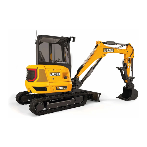
- Page 1 Quick Start Guide Compact Excavators 35Z-1 / 36C-1...
-
Page 2: Table Of Contents
Index Intended Use.......................3 Dimensions ......................4 Tie Down Points ....................5 Lifting Points .......................6 Cab Layout & Controls................... 7-10 Start Up Sequence ....................11 Machine Health Check & Shut Down Sequence …………………………………..……12 Hydraulic Hitch Unlock ……………………………..………………………………………………13 Mechanical Hitch Unlock & Maintenance Position ...........14 Service / Maintenance..................15 Service &... -
Page 3: Intended Use
Intended Use General Machine type – Compact Excavator Self propelled machine with a tracked undercarriage 360° revolving upper structure with boom, dipper, bucket and slew mechanism Intended Use Machine intended to be used in normal conditions as detailed in the operators manual ... -
Page 4: Dimensions
Dimensions Item Description 35Z-1 36C-1 Sprocket idler centres 1590mm Track length on ground 1590mm Undercarriage overall length 2049mm Kingpost clearance 555mm Tailswing radius – Light CW 900mm 1200mm Tailswing radius – Heavy CW 1000mm 1300mm Overall width of 1550mm superstructure... -
Page 5: Tie Down Points
Tie down points Method 1 Method 2 3 5 Z - 1 , 3 6 C - 1 | 5... -
Page 6: Lifting Points
Lifting Points Carry out the following procedure when lifting a machine: 1. Remove all attachments 2. Remove all loose equipment from machine exterior 3. Check the unladen weight of the machine 4. Attach lifting equipment to each end of the dozer blade. Correct lift-point positions are identified on the machine by a label. -
Page 7: Cab Layout & Controls
Cab Layout & Controls Component Locations A. Track Controls B. Excavator controls C. Dozer blade control lever D. Throttle control E. Switch console F. Entertainment system G. Air-conditioning controls H. Operator seat J. ISO/SAE control pattern switch K. Instrument panel L. - Page 8 Cab Layout & Controls Instrument Panel SAE active Air filter (blocked) indicator Seat belt Park brake Engine pre-heat Master warning After treatment critical warning Axle lock Fuel indicator Coolant temperature Engine oil pressure Battery charging condition Swing active Hydraulic active High travel speed Dozer blade, float After treatment critical warning...
- Page 9 Cab Layout & Controls Excavator Levers (ISO Control Pattern) Excavator Levers (SAE Control Pattern) 3 5 Z - 1 , 3 6 C - 1 | 9...
- Page 10 Cab Layout & Controls Swing Control Switch A. Swing left B. Swing right C. Swing control switch Auxiliary Controls A. Left electro-proportional switch for aux 2 (low flow) B. Tilt/grab changeover for tilt-rotator C. Boom swing/AUX changeover D. Right finger button – High flow AUX maximum preset flow button (momentary/latching depending on settings in menu) E.
-
Page 11: Start Up Sequence
Start Up Sequence 3 5 Z - 1 , 3 6 C - 1 | 11... -
Page 12: Machine Health Check & Shut Down Sequence
B. Coolant level low C. Blocked air filter D. Water in fuel indicator E. ‘Master warning’ – contact JCB dealer Shut Down Sequence 12 | P l e a s e s e e o p e r a t o r m a n u a l f o r f u l l d e t a i l s . -
Page 13: Hydraulic Hitch Unlock
Hydraulic Hitch Unlock System 3 5 Z - 1 , 3 6 C - 1 | 13... -
Page 14: Mechanical Hitch Unlock & Maintenance Position
Mechanical Hitch Unlock System Maintenance Position 1. Park machine on solid, level ground 1.1. Release the two track levers 1.2. Set handle throttle lever to idle position 2. Lower the dozer blade (B) 3. Lower excavator so attachment is flat on ground (A) 4. -
Page 15: Service / Maintenance
Service and Maintenance Daily Checks (10h) Action Check condition of attachments / optional equipment Visual Check Grease attachments / optional equipment / pivot pins as required Lubricate Clean bodywork and framework Clean Check condition of bodywork and framework Visual Check Check condition of cab/canopy including seat belt Visual Check Check engine for leaks and oil level... -
Page 16: Service & Access Covers
Service and Access Covers Engine Compartment Cover Hydraulic Compartment Cover Toolbox 16 | P l e a s e s e e o p e r a t o r m a n u a l f o r f u l l d e t a i l s . - Page 17 Service and Access Covers Engine Compartment A. Main fuel filter B. Overflow bottle C. Coolant system filter cap D. Air filter E. Air conditioning condenser (if fitted) F. Engine oil dipstick G. Engine oil filler cap R. Radiator Hydraulic Compartment H.
-
Page 18: Fluids & Lubricants
4001/3700 30 HP Engine coolant 7.3L (Cab) JCB Antifreeze 4006/1120 6.4L (Canopy) HP/Coolant/Water Track gearbox 0.8L JCB Engine Oil HP 4001/0305 SAE 30 (Not Multigrade) Track idler wheel 0.8L JCB HP90 Gear oil 4000/0305 Track roller (Top) 0.003L JCB HP90 Gear oil...


Need help?
Do you have a question about the 35Z-1 and is the answer not in the manual?
Questions and answers