
Related Manuals for Vulcan-Hart 7801A


Summary of Contents for Vulcan-Hart 7801A
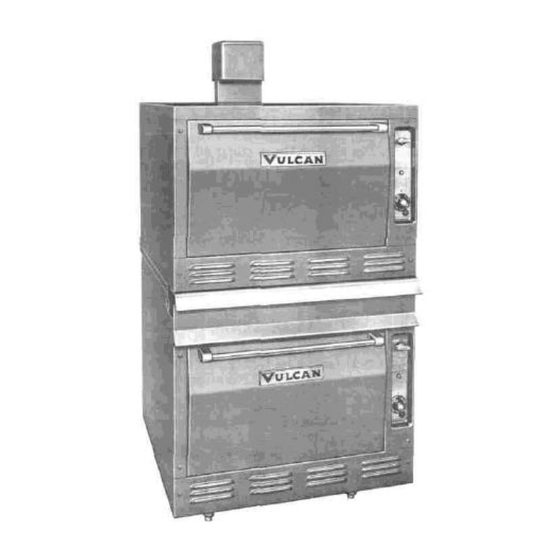
- Page 1 INSTALLATION, SERVICE & PARTS MANUAL FOR 7801A, 7802A & M7801A ROASTING OVENS VULCAN-HART CORPORATION, 3600 NORTH POINT BOULEVARD, BALTIMORE, MARYLAND 21222...
- Page 2 Qualified service personnel are those who are familiar with Vulcan equipment who have been endorsed by the Vulcan-Hart Corporation. All authorized service personnel are required to be equipped with a complete set of service parts manuals and stock a minimum amount of parts for Vulcan equipment.
- Page 3 ADDENDUM GAS COOKING EQUIPMENT MANUALS WARNING IMPROPER INSTALLATION, ADJUSTMENT, ALTERATION OR MODIFICATION, SERVICE OR MAINTENANCE CAN CAUSE PROPERTY DAMAGE, INJURY OR DEATH. READ THE INSTALLATION, OPERATING AND MAINTENANCE INSTRUCTIONS THOROUGHLY BEFORE INSTALLING OR SERVICING THIS EQUIPMENT. Clearances listed in this manual apply to combustible and non-combustible materials. H Series Gas Range clearances are now 9"...
- Page 4 IMPORTANT NOTES FOR ALL VULCAN APPLIANCES 1. These units are produced with the best possible workmanship and material. Proper installation is vital if best performance and appearance are to be achieved. Installer must follow the installation instructions carefully. 2. Information on the construction and installation of ventilating hoods may be obtained from the "Standard for the installation of equipment for the removal of smoke and grease laden vapors from commercial cooking equipment,"...
- Page 5 7800 SERIES RANGES-INSTALLATION, SERVICE AND PARTS MANUAL INDEX Vulcan ranges and ovens are produced with the best possible The manufacturer suggests that you thoroughly read this entire workmanship and material. Proper usage and maintenance will manual and carefully follow all of the instructions provided. result in many years of satisfactory performance.
- Page 6 BUMPER BAR INSTALLATION 7800 SERIES UNITS INSTALLATION PROCEDURE: WARNING: 1. REMOVE EXISTING 1/4-20 FAILURE TO INSTALL BUMPER BARS MAY SCREWS INDICATED. CAUSE MOTOR DAMAGE AND WILL VOID 2. POSITION BUMPER BARS AS SHOWN WARRANTY. 3. REPLACE 1/4-20 SCREWS AND SECURE BUMPER BARS AS SHOWN.
-
Page 7: Uncrating Instructions
INSTALLATION INSTRUCTIONS FOR VULCAN 7800 SERIES (INCLUDES ALL UNITS WITH OR WITHOUT OVENS MATERIALS. PROPER INSTALLATION IS VITAL i.e. MODULAR & EXPANDOS.) IF BEST PERFORMANCE AND APPEARANCE IS T0 BE ACHIEVED. PLEASE FOLLOW THESE THE VULCAN RANGE IS PRODUCED WITH THE INSTRUCTIONS CAREFULLY. - Page 8 UNIT INSTALLATION PROCEDURES (Cont'd.) 11. Adjust top burner pilot flames to a point where only a trace of yellow remains, this adjustment insures the best operating conditions. 12. The pressure regulator must be A.G.A. design certified. Regulators must have regulation capacity for total connected load.
- Page 9 OVEN TEMP. CONTROLS 7800 SERIES 4 . Replace dial. CAUTION While making this adjustment, OVEN TEMPERATURE CONTROLS 7800 INSTRUCTIONS FOR ROBERTSHAW MODEL FDO if the oven should become heated while the dial is set HEAVY DUTY FLAME MASTER OVEN CONTROL. This at a low range (below 350), the bypass flame will shut model FDO is a precision made instrument, carefully set off completely.
- Page 10 OVEN TEMPERATURE CONTROL 7800 SERIES THERMOSTATICALLY CONTROLLED GRIDDLE, the thermostat is a slotted screw adjustment marked "B" INSTALLATION see figure 1. This will adjust the by-pass gas only, counter clockwise to increase clockwise to decrease, Set metal brick supports in place, narrow ones (1) each adjust flame to approximately 1/8"...
-
Page 11: Temperature Control Calibration
TEMPERATURE CONTROL CALIBRATION OVEN TEMPERATURE CONTROL RECALIBRATION your reading is not within 15 degrees of the dial Field recalibration is seldom necessary, and should not setting. If recalibration is required, proceed as follows: be resorted to unless experience with cooking results, 5. - Page 12 TEMPERATURE CONTROL RECALIBRATION (Cont'd.) KX RECALIBRATION 1. Place the thermocouple of test instrument on the thermostat bulb. Close oven door. 2. Light the main burner by turning thermostat to 500° dial setting. 3. Allow the oven to heat until flame cuts off. After several cycles, check temperature.
- Page 13 LIGHTING, OPERATION and SHUTTING DOWN (OVEN SECTION) LIGHT OVEN BURNER AS FOLLOWS: C. MAKE SURE ALL BURNER VALVES AND MAIN SUPPLY VALVES ARE OFF. D. TO RETURN UNITS TO OPERATION OPEN MAIN GAS SUPPLY REPEAT STEPS 14 THRU 19 ON PAGES 6 TURN BURNER VALVE "ON"...
- Page 14 AUTOMATIC SAFETY PILOT INSTRUCTIONS 3 . Do not remove interrupter valve for field RECALIBRATION PROCEDURE service. Make note of number of degrees thermostat is off. Remove thermostat dial and loosen calibration NOTE: Make certain gas line to inlet of control is screws, see drawing, until plate moves freely.
- Page 15 TROUBLE SHOOTING (PROBLEMS & CAUSES) PROBLEM PROBABLE CAUSES OVEN TOO MUCH BOTTOM HEAT INSUFFICIENT HEAT INPUT OVER ACTIVE FLUE UNEVEN BAKE TOO LOW TEMPERATURE IMPROPER OPERATION SIDE BURNING IMPROPER BY-PASS SETTING FLUCTUATING GAS PRESSURE TOO MUCH TOP HEAT TOO HIGH TEMPERATURE FAULTY VENTILATION EXCESSIVE HEAT INPUT THERMOSTAT CALIBRATION...
-
Page 16: Replacement Parts List
THIS INFORMATION CAN BE FOUND ON THE INSTRUCTION PLATE ON FRONT OF THE UNIT. PARTS MAY BE ORDERED FROM YOUR DEALER, SERVICE AGENCY, OR THE FACTORY. ORDERS TO THE FACTORY SHOULD BE ADDRESSED: VULCAN-HART CORPORATION REPAIR PARTS DEPARTMENT 3600 NORTH POINT BLVD. - Page 17 Insert B...
- Page 18 REPLACEMENT PARTS LIST 109557-4 109557.4 3/16 Top Pilot Valve 7856A, 54A, 53-72A 109557-4 SG7856A, 54A 53-72A 104738-2 104738-2 3/16 Single Top Pilot Valve 7856A, SG7856A 104738-2 104738-2 102601 102601 Top Burner Valve 7830A, SG7830A 102601 102601 109433-1 109433-1 Top Aeration Plate 7845A, SG7845A 109432-1 109432-1...
- Page 19 REPLACEMENT PARTS LIST ORIFICE PART No. DESCRIPTION Burner Drill Size No. 7830 VALVES 7830 102601-44A VALVE, TOP BURNER ADJ. NAT. OUTER 44 (.086) 102601-56F VALVE, TOP BURNER FIXED L/P BUT. OUTER 55 (.052) 102601-55F VALVE, TOP BURNER FIXED L/P Prop. OUTER 54 (.050) 102601-48A...
-
Page 20: Cooking Chart
COOKING CHART IMPORTANT A pan of water (approximately 12" x 20" x 1") may be placed Recommended temperatures, times, number of racks and in the oven bottom. This water supplies humidity to reduce load control settings are intended as a guide only. shrinkage. - Page 21 COOKING CHART (Continued) RECOMMENDED TEMPERATURES, TIMES AND LOADS FOR BAKING PRODUCT TEMPERATURE TIME IN LOAD Yeast Bread* Note: Yeast Breads should be fully proofed for best Sweet Rolls & Danish Pastries 325° to 375° F 5 to 15 Med to Med- Med-to Lo+ Quick Breads Biscuits 350°...
- Page 22 WIRING DIAGRAM—7800 SERIES REV# DATE SIGN 6/3/80 8/2/80 9/11/8 RWR...
Need help?
Do you have a question about the 7801A and is the answer not in the manual?
Questions and answers