Table of Contents
Advertisement
Quick Links
Advertisement
Table of Contents

Related Manuals for ViscoTec RD-EC


Summary of Contents for ViscoTec RD-EC
- Page 1 Operating and Assembly Instructions Dispenser RD-EC...
-
Page 2: Table Of Contents
Dismantling the dispenser ........15 Operating and Assembly Instructions 2 / 27 Dispenser RD-EC... - Page 3 Dimensions ..........27 Disposal Operating and Assembly Instructions Dispenser RD-EC 3 / 27...
-
Page 4: Introduction
We would be happy to consider any suggestions you may have on how we might improve our products. Do you have any questions? We look forward to hearing from you: ViscoTec Pumpen- u. Dosiertechnik GmbH. Amperstrasse 13 D-84513 Toeging am Inn Tel.: +49(0)8631/9274-0... -
Page 5: Function Description
The design also conveying and metering of highly abrasive media. ViscoTec dispensers are rotating displacement pumps. The conveying elements comprise a rotating part, the "rotor", and a stationary part, the "stator". The rotor, which is in the form of a type of round thread, rotates inside the stator, which has one more thread turn and twice the pitch length of the rotor. -
Page 6: Safety
- when pumping without positive feed (primary pressure), no dry running or cavitation occurs in the dispenser. - the direction of rotation of the drive is always the same as the pumping direction of the dispenser. - the volumetric efficiency is >80 %. Operating and Assembly Instructions 6 / 27 Dispenser RD-EC... -
Page 7: Correct Use, Warranty
(DIN standards) that he/she can evaluate if the dispenser is safe. Operating and Assembly Instructions Dispenser RD-EC 7 / 27... -
Page 8: Organisational Measures
If there is any doubt at that the unit is not perfectly ready for operation, it must be shut down at once and inspected by a suitably qualified person before it is used again. Operating and Assembly Instructions 8 / 27 Dispenser RD-EC... -
Page 9: Operation
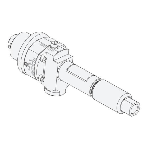
Setscrew, stator fastening (protection against turning) Machine number Type designation Order number Counter-clockwise rotation Fig. 1 Preferred metering direction: 1A inlet, 1B outlet, anti-clockwise rotating dispenser (as seen looking on the drive end) Operating and Assembly Instructions Dispenser RD-EC 9 / 27... -
Page 10: Starting Up For The First Time
Air bubbles can cause uncontrollable spurting out. Ensure that you stand back a safe distance. It is recommended that you wear suitable protective clothing under these circumstances. Fig. 2 Operating and Assembly Instructions 10 / 27 Dispenser RD-EC... -
Page 11: Shutting Down
Page 7. Servicing intervals The dispenser is to be considered largely maintenance-free. To ensure trouble-free operation, we recommend carrying out a regular check depending on the product to be processed. Operating and Assembly Instructions Dispenser RD-EC 11 / 27... -
Page 12: Stator Replacement
Fig. 3 Tip: When unscrewing / pulling off the stator, it can be helpful to lock the drive shaft with a suitable tool (pin, screwdriver, etc.) to prevent it from turning. Operating and Assembly Instructions 12 / 27 Dispenser RD-EC... -
Page 13: Fitting The Stator
Tip: When screwing / pushing on the stator, it can be helpful to lock the drive shaft with a suitable tool (pin, screwdriver, etc.) to prevent it from turning. * Recommended thread locking compound: Loctite® 572 Operating and Assembly Instructions Dispenser RD-EC 13 / 27... -
Page 14: Cleaning The Dispenser
• Remove the stator as described in the previous section. • Remove the 4 screws (12) • Pull the rotor assembly (1) with the O-ring (27) out of the dispenser housing (3). Fig. 6 Operating and Assembly Instructions 14 / 27 Dispenser RD-EC... -
Page 15: Dismantling The Dispenser
• Dismantle the dispenser as outlined in section 4.3. • Remove the 3 screws (11). • Pull out the rotor assembly (1) with shaft sealing units (D) and (E) out of the dispenser housing (3) Fig. 7 Operating and Assembly Instructions Dispenser RD-EC 15 / 27... - Page 16 (E). This is located in the bearing seal housing (2, Fig. Fig. 9). Fig. 8 • Unscrew both plugs (13). • Undo the bleed screw (14) with washer (sealing washer) (15). • Remove the setscrew (16). Fig. 9 Operating and Assembly Instructions 16 / 27 Dispenser RD-EC...
-
Page 17: Reassembling The Dispenser
The sealing chamber (H, Fig. 10) in the spacer (19) - between the two rotary shaft seals (20) - must be filled with a sealing medium resistant to aggressive media. We recommend OKS 469. Operating and Assembly Instructions Dispenser RD-EC 17 / 27... -
Page 18: Filling The Sealing Chamber With Sealing Medium
At the same time the contact surface on the drive shaft - at which the rotary shaft seals provide the seal - must be checked for damage (grooves where the seals run). If necessary, replace the drive shaft. Fig. 10 Operating and Assembly Instructions 18 / 27 Dispenser RD-EC... -
Page 19: Applying Sealing Medium To The Rotary Shaft Seal During Assembly
(20) pressed into the spacer (19). In this way sufficient sealing medium is applied to the shaft sealing unit (E). Wipe off excess sealing medium after assembly of the shaft sealing units. * We recommend OKS 469. Fig. 11 Operating and Assembly Instructions Dispenser RD-EC 19 / 27... -
Page 20: Troubleshooting
Shut down drive, check pipes and medium Increase in dispenser running Excessive back pressure Check pipes, nozzles, clean or noise (pipes, nozzles blocked) replace. Stator / rotor worn Change stator / rotor Operating and Assembly Instructions 20 / 27 Dispenser RD-EC... -
Page 21: Ordering Spare Parts
The data are also engraved on the dispenser ( see 3.1, Fig. 12 General overview of the dispenser, Page 9). Select the correct spare parts for your dispenser type using the drawing below and the relevant column in the item list. Operating and Assembly Instructions Dispenser RD-EC 21 / 27... -
Page 22: Spare Parts And Wearing Parts, Drawing And Parts List
Spare parts and wearing parts, drawing and parts list Fig. 13 Operating and Assembly Instructions 22 / 27 Dispenser RD-EC... - Page 23 Operating and Assembly Instructions Dispenser RD-EC 23 / 27...
-
Page 24: Recommended Spare Parts And Wearing Parts
Please see column S in the item list on the previous page. We would be pleased to prepare a quotation for a maintenance and service contract to suit your application or we can provide a repair kit. Operating and Assembly Instructions 24 / 27 Dispenser RD-EC... -
Page 25: Technical Specification
Technical specification Declaration of incorporation within the meaning of EU Directive 2006/42/EU on machinery Annex II B ViscoTec – Pumpen- u. Dosiertechnik GmbH Amperstr. 13, 84513 Töging hereby declare that in the design and manufacture of the incomplete machine described below that the following basic requirements of EU Directive 2006/42/EU had been applied and complied with: 1.1.2, 1.1.3, 1.1.5, 1.3.2, 1.5.4, 1.6.1, 1.6.2, 1.7.4, 1.7.4.1, 1.7.4.2... -
Page 26: Technical Data
Rotary shaft seal (L), high pressure rotary shaft seal PTFE 40% GF Rotor coating Hard chromium plated Rubberised flex-shaft VisChem Stator, see page 24 * Viton ® is a DuPont brand Operating and Assembly Instructions 26 / 27 Dispenser RD-EC... -
Page 27: Dimensions
Dispose of the dispenser in an environmentally safe way. All materials and products left in containers must be treated in accordance with the appropriate recycling requirements. z_letzte_Seite Field for the type plate sticker for this dispenser Operating and Assembly Instructions Dispenser RD-EC 27 / 27... - Page 28 E-Mail: mail@viscotec.de ViscoTec Pumpen- u. Dosiertechnik GmbH Telefon: +49(0)8631/9274-0 Amperstr. 13 | 84513 Töging a. Inn | Germany Internet: www.viscotec.de Fax: +49(0)8631/9274-300...
Need help?
Do you have a question about the RD-EC and is the answer not in the manual?
Questions and answers