Table of Contents
Advertisement
Quick Links
Advertisement
Table of Contents

Related Manuals for ViscoTec Preeflow eco-PEN600


Summary of Contents for ViscoTec Preeflow eco-PEN600
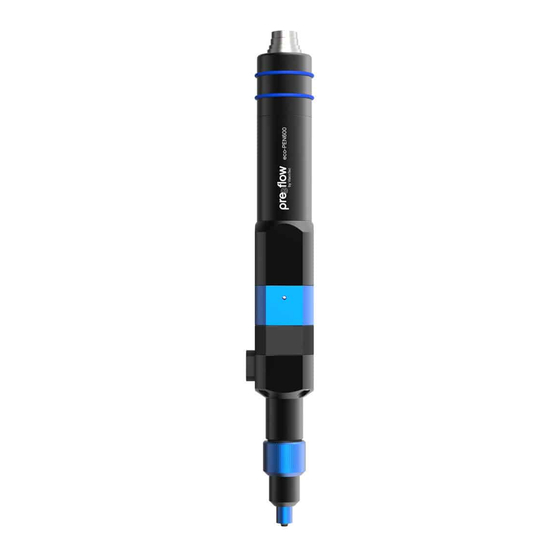
- Page 1 OPERATION & MAINTENANCE MANUAL eco-PEN600...
-
Page 2: Table Of Contents
TABLE OF CONTENTS Introduction ...................... 4 Delivery package ..................4 Incoming inspection ................. 5 Safety ........................ 6 Explanation of symbols used ..............6 Intended use .................... 7 Personnel....................8 2.3.1 Operators..................8 2.3.2 Maintenance staff ................ 8 Informal safety precautions..............8 Preventing damage to equipment ............ - Page 3 TABLE OF CONTENTS Maintenance ....................18 Maintenance intervals ................18 Troubleshooting ..................19 Stator change..................20 5.3.1 Disconnecting the dosing unit and drive unit ......20 5.3.2 Removing the stator..............21 Dismantling before cleaning..............22 Cleaning ......................23 Spare parts ..................... 24 Item list of the spare parts..............
-
Page 4: Introduction
INTRODUCTION Introduction Dear customer, We are delighted that you have decided to purchase a ViscoTec product. We have no doubt that this product will meet all your requirements. We wish you trouble-free and successful operation. The dosing system consists of the eco-PEN600 dispenser and the eco-CONTROL EC200 dosing control unit or the plug´n´dose dosing control unit. -
Page 5: Incoming Inspection
INTRODUCTION Incoming inspection Damage in transit can lead to malfunctions, and consequently to personal injury and damage to property. Damaged components must not be put into operation. Check the delivery immediately on receipt for damage in transit and damage to the packaging. -
Page 6: Safety
SAFETY Safety Explanation of symbols used The following symbols are used in this manual: Work step • List Fig. 1 Legend number, reference to a figure Reference to a comment COMMAND Designations of buttons/switches, menu items and input dialogs The following notices indicate safety instructions and must be followed: DANGER indicates a hazardous situation which, if not avoided, will result in death or serious injury. -
Page 7: Intended Use
SAFETY Intended use The eco-PEN600 dispenser is used to feed and precisely dose viscous materials. The dispenser is controlled using the eco-CONTROL EC200 dosing control unit or the plug´n´dose dosing control unit. Check the chemical resistance of the materials that are in contact with the material before commissioning. -
Page 8: Personnel
SAFETY Personnel The operating organisation shall ensure that only appropriately qualified and authorised personnel work on this machine. It is responsible for ensuring that operators and maintenance staff possess the necessary qualifications. Personnel must be at least 15 years old. All personnel working with or on the machine must have read and understood this operation manual. -
Page 9: Preventing Damage To Equipment
SAFETY Preventing damage to equipment In order to prevent damage to equipment and to ensure precision dosing, note that • the dispenser must never be operated without material (the stator will be destroyed) • the material inlet (feed) and the material outlet must never be closed during operation •... -
Page 10: Residual Risks
SAFETY Residual risks Thorough training, observance of the operation manual and compliance with safety regulations are key to permanently accident-free operation. The following residual risks may occur when operating this machine: WARNING Material hazardous to health The conveyed material may contain constituents which are hazardous to health. Such constituents may cause serious acute or chronic harm to health if they come into contact with skin, are inhaled or swallowed. -
Page 11: Transport And Storage
SAFETY CAUTION Splashing material During initial commissioning and after being refilled, air bubbles in the material could cause an uncontrollable spraying from the conveying area. This may result in injury. • Always wear appropriate protective equipment • Fully bleed the system before start of production CAUTION Pointed dosing needle Depending on its size, the dosing needle can be very thin and pointed. -
Page 12: Product Description
PRODUCT DESCRIPTION / OPERATION Product description The dispenser has been developed and tested for precision dosing of materials ranging from low to high viscosity with extremely high repeat accuracy. preeflow dispensers are positive displacement pumps. The conveying elements comprise a rotating part, the "rotor", and a stationary part, the "stator". -
Page 13: Fitting The Stator
OPERATION 4.1.1 Fitting the stator Coat the rotor (4) with material or a suitable lubricant. Turn the stator (7) in the correct position (see detailed view) on the rotor (4) until the dowel pin (8) begins to dip into the keyway (9). Lightly press the stator (7) towards the pump housing (19) and turn the assembly aid (6) in ... -
Page 14: Feeding Material And Bleeding The Dispenser For The First Time
OPERATION 4.1.3 Feeding material and bleeding the dispenser for the first time Preparation Connect the material supply (feed line, cartridge) to the material inlet (12) of the dispenser. The dispenser can be bled in one of two ways after the medium has been supplied. Version A (e.g. - Page 15 OPERATION Version B (e.g. open cartridge, dispenser fixed in place and supply of the material under pressure) Turn the bleed screw (23) 180 degrees so that the bleed hole (8) is in the position shown (direction of the drive unit). Pressurise the material.
-
Page 16: Calibration
OPERATION 4.1.4 Calibration To obtain a precise dosing result, the dosing quantity must be calibrated. This is performed using the eco-CONTROL EC200 dosing control unit. The exact procedure can be found in the dosing control unit manual. Switching on, starting dosing process Daily at the start of the shift / when starting work, perform the activities as described in Section 5.1 “Maintenance intervals”... -
Page 17: Decommissioning
OPERATION Decommissioning All activities described below may only be carried out by authorised maintenance staff. Switch off the drive to the dispenser and lock it to prevent it from being switched on again. Shut down material supply to the dispenser (depressurise). ... -
Page 18: Maintenance
MAINTENANCE Maintenance In the event of a fault, or if there is any doubt that the machine/system is not completely ready for operation, it must be shut down immediately and inspected by competent maintenance staff before operation continues. WARNING Maintenance and cleaning work may only be carried out when the machine has been shut down safely and secured against unauthorised restarting. -
Page 19: Troubleshooting
MAINTENANCE Troubleshooting Fault Possible cause Action Motor not connected Connect the motor Fault with mains supply Check electrical installation Material hardened/set Dismantle and clean the dispenser Dosing needle blocked Clean/replace dosing needle Dosing needle too small or too Use a different needle cross- long section. -
Page 20: Stator Change
MAINTENANCE Stator change All activities described below may only be carried out by authorised maintenance staff. Preparation Disconnect the dosing control unit from the power supply. Unplug the power supply to the drive unit. Shut down material supply (depressurise). ... -
Page 21: Removing The Stator
MAINTENANCE 5.3.2 Removing the stator Undo the cap nut (2). Pull off the end piece (3). Plug the star-shaped coupling (5) into the bearing housing (13). Couple the assembly aid (6) to the bearing housing (13). Unscrew stator (7) with assembly aid (6). -
Page 22: Dismantling Before Cleaning
MAINTENANCE Dismantling before cleaning When cleaning the dispenser, attention must be paid to the chemical properties and chemical reactions of the material. In doing so, observe and comply with the corresponding specifications of the product data sheet. If you have any queries, contact the manufacturer of the material. -
Page 23: Cleaning
CLEANING Cleaning WARNING Cleaning work may only be carried out when the machine has been shut down safely and secured against unauthorised restarting. Otherwise, serious injuries may result. • Switch off the dosing control unit. • Disconnect the dosing control unit's power cable from the power supply If the dispenser is soiled with material or if the dispenser is disassembled and cleaned, use a cleaning agent which matches the material. -
Page 24: Spare Parts
SPARE PARTS Spare parts Every time you order spare parts, please state the type identifier, serial number and order number. The serial number is engraved on the bearing housing (13). Item list of the spare parts Item Description Part No. Material eco-PEN600 dosing unit, cpl. -
Page 25: Overview Drawing Of The Spare Parts
SPARE PARTS Overview drawing of the spare parts Fig. 9 INST-002752 / A eco-PEN600 25 / 32... -
Page 26: Technical Specifications
Technical specifications Installation declaration Within the meaning of EU Directive 2006/42/EU on Machinery Annex II B ViscoTec Pumpen- u. Dosiertechnik GmbH Amperstraße 13 D-84513 Töging am Inn, hereby declare that, in the design and manufacture of the incomplete machine described below, the following basic requirements of EU Directive 2006/42/EC have been applied and complied with: 1.1.2, 1.1.3, 1.1.5, 1.3.2, 1.5.4, 1.6.1, 1.6.2, 1.7.4, 1.7.4.1, 1.7.4.2... -
Page 27: Technical Data
TECHNICAL SPECIFICATIONS Technical data eco-PEN600 Weight approx. 650 g Minimum operating pressure 0 bar, with self-levelling liquid Maximum operating pressure 6 bar, with non self-levelling liquid Maximum dosing pressure 20 bar Self sealing approx. 2 bar (reference material approx. 10 mPas at 20 °C) Motor 18 to 24 V DC, incremental encoder, planetary gear... -
Page 28: Materials Used
TECHNICAL SPECIFICATIONS Materials used Material Components in contact with the material Dispenser housing, end nozzle HD-POM Dispenser parts, motor housing Anodized aluminium Screws, washers, etc. Stainless steel A2 Stator elastomer, flexible shaft covering VisChem Shaft sealing rings O-rings FKM, FFKM Drive shaft, rotor Stainless steel A4 Dimensions... -
Page 29: Disposal
DISPOSAL / ACCESSORIES Disposal The dispenser must be removed by competent maintenance staff. Disposal may only be performed in line with the currently applicable, country-specific specifications, standards and legislation. Ensure environmentally friendly recycling of all materials. Electrical parts must not be disposed of with household waste (2012/19/EU). They must be taken to the collection points provided for this purpose or disposed of in an environmentally appropriate way. - Page 30 Notes 30 / 32 eco-PEN600 INST-002752 / A...
- Page 31 Notes INST-002752 / A eco-PEN600 31 / 32...
- Page 32 OPERATION & MAINTENANCE MANUAL eco-PEN600 Project number: 14X-XX-XXXX Order number: 14X-XX-XXXX © Copyright 2020 ViscoTec Pumpen- u. Dosiertechnik GmbH Amperstraße 13 D-84513 Töging am Inn Germany This document is protected by copyright. It must not be modified, extended, reproduced or distributed to third parties without written consent.
Need help?
Do you have a question about the Preeflow eco-PEN600 and is the answer not in the manual?
Questions and answers