Advertisement
Available languages
Available languages
Quick Links
Advertisement

Related Manuals for GOOD HOUSEKEEPING Abbey


Summary of Contents for GOOD HOUSEKEEPING Abbey
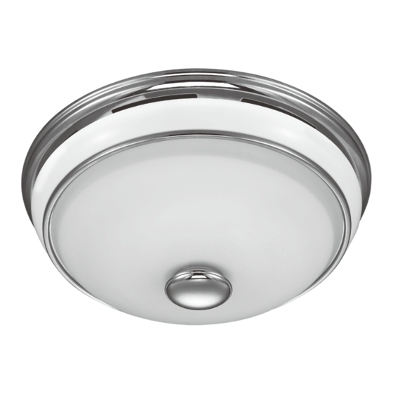
- Page 1 Abbey Bath Ventilator with Light Owner’s Manual Model 42105-01 81021 R20230830...
-
Page 2: Preventative Maintenance
W A R N I N G TO REDUCE THE RISK OF FIRE, ELECTRIC SHOCK, OR INJURY TO PERSONS, OBSERVE THE FOLLOWING: and the American Society for Heating, Refrigeration and Air- 1. Use this unit only in a manner intended by the manufacturer. If you have questions, contact the manufacturer. - Page 3 Check all the parts. If damaged, call 1-888-880-3267 Extra Screws for replacements. 3/8" Cable Connector * NOTE: Strain relief cable connector must be installed. Not Included. 95044-01-000 95029-01-000 77481-01-000 03242-07-133 98037-03-000 74508-03-133 77521-01-000 65219-01-000 97956-01-000 75184-01-133 97958-01-000 77537-01-199 Included. ools Needed. Not Included. Estimated assembly time: 30 to 60 minutes 42105-01 R20230830...
-
Page 4: Before Installation
Before Installation NOTE: Remove all packing materials before installation. Turn off the power source. Loosen screws. Remove the motor/blower from the housing. Remove packing material. Remove the pre-loaded screw tip covers. Back out the pre-loaded screw tips until flush with the side of the housing. 42105-01 R20230830... - Page 5 Remove the wiring cover screw. Remove the wiring cover. Pop out the first wiring access slug. Use second if needed. Insert the strain relief into the housing and secure with the washer. Choose Installation Option For New Construction - attaching to joist go to step A11, page 6 For New Construction - suspended between joists go to step B11, page 8 For Existing Construction - accessible from above go to step C11, page 12 For Existing Construction - accessible only from below go to step D11, page 16...
- Page 6 New Construction – attaching to joist Position the correct depth mark at the bottom edge of Screw pre-loaded screws into joist or framing. the joist based on the thickness of your sheetrock. Pull wires through the strain relief. Tighten the strain relief screws. Ground Black Green...
- Page 7 Connect 4" duct and vent to the outside. Tape joints. Install the wiring cover plate. Make sure all If ducting does not fit securely, an adapter may need wiring connections are inside the box or under to be purchased. the wiring cover plate. 0 0 0 0 0 0 0 0 Connect wiring from the motor to the wiring cover...
- Page 8 Go to step on page 18 to attach grill. Test the motor. If the motor does not run, check the plug connection. New Construction – suspended between joists Slide the mounting rails into brackets. Position the correct depth mark at the bottom edge of the joist based on the thickness of your sheetrock.
- Page 9 Insert screws, leaving space between the screw Attach the rails onto the screws. head and the joist. Screws are not provided. Tighten screws. Pull wires through the strain relief. Tighten the strain relief screws. 42105-01 R20230830...
- Page 10 Ground Black Green 2 Pin Bare Copper White Black Main Switch 1 (AC In) Fan Motor White White 3 Pin Black Light Light *Option Black Switch 2 (AC In) *Option Fan & Main Light Together Connect wires as shown. Install the wiring cover plate. Make sure all wiring Connect 4"...
- Page 11 Secure the motor by tightening the 2 screws. Turn on the power source. Go to step on page 19 to attach grill. Test the motor. If the motor does not run, check the plug connection. 42105-01 R20230830...
- Page 12 Existing Construction – accessible from above EXISTING FAN NO EXISTING FAN Remove an existing fan and check to make sure the Use the motor housing as a template to mark position. opening is large enough to accommodate the new motor housing (8"x 8.5"). Cut out an opening for the housing.
- Page 13 " 8 t i B Drill a hole in the center of each outline. Insert screws, leaving space between the screw head and the joist. Screws are not provided. Attach the rails onto the screws. Tighten screws. Connect 4" duct and vent to the outside. Tape joints. Pull wires through the strain relief.
- Page 14 Tighten the strain relief screws. Ground Black Green 2 Pin Bare Copper White Black Main Switch 1 (AC In) Fan Motor White White 3 Pin Light Black Light *Option Black Switch 2 (AC In) *Option Fan & Main Light Together Connect wires as shown.
- Page 15 Reinstall the motor by inserting the tabs and pushing Secure the motor by tightening the 2 screws. up into position. Make sure the wires are not pinched between the motor and the housing. Turn on the power source. Test the motor. If the motor does not run, check the plug connection.
- Page 16 Existing Construction – accessible only from below EXISTING FAN Remove an existing fan and check to make sure the Move the housing into position above the ceiling. opening is large enough to accommodate the new motor housing (8"x 8.5"). Attach existing ducting to duct connector. Pull wires through strain relief.
- Page 17 Ground Black Green 2 Pin Bare Copper White Black Main Switch 1 (AC In) Fan Motor White White 3 Pin Black Light Light *Option Black Switch 2 (AC In) *Option Fan & Main Light Together Connect wires as shown. Connect wiring from the motor to the wiring cover plate. Install the wiring cover plate.
- Page 18 Turn on the power source. Test the motor. If the motor does not run, check the plug connection. Go to step on page 19 to attach grill. 42105-01 R20230830...
- Page 19 Remove the thumbscrews. Connect wiring harness. Remove the strain relief bracket screw. Position the strain relief bracket under the motor as shown. Insert the strain relief bracket’s dog-leg tab so that it Align posts A, B, C and D (stamped into motor housing) hooks over the lip of the motor.
- Page 20 Attach thumbscrews. Install 2 LED Max 8 watt A-15 bulbs (Not Included) WARNING: To reduce the risk of electrical shock, all 4 thumbscrews MUST be properly installed. Align glass dome and push up Screw finial into position Complete. 42105-01 R20230830...
-
Page 21: Troubleshooting
Check the flapper to make sure it moves freely. If you need any assistance with setup, operation, or parts for your new Good Housekeeping bath exhaust fan, please call us. Our technical support staff is ready to help! We are open 24 hours a day, 7 days a week. - Page 22 Good Housekeeping bath exhaust fan motor fails at any time within two years after the date of sale to you due to a defect in material or workmanship, labor and materials to repair the defect will be provided free of charge at our nearest service center or our Service Department in Kennesaw, Georgia.
- Page 23 Abbey Ventilador para baño con luz Manual del Propietario Modelo 42105-02 81021 R20230830...
-
Page 24: Mantenimiento Preventivo
A D V E R T E N C I A PARA REDUCIR EL RIESGO DE INCENDIO, CHOQUE ELÉCTRICO O LESIONES A PERSONAS, OBSERVE LO SIGUIENTE : 1. Utilice esta unidad sólo de la manera indicada por el fabricante. Ingenieros Americanos en Calefacción y Aire acondicionado Si tiene alguna pregunta, contacte con el fabricante. - Page 25 Verifique todos los componentes. Si están daña- dos, llame al 1-888-880-3267 Tornillos para obtener un reemplazo. adicionales Conector de cable de 3/8" * NOTA : Debe estar instalado el manguito de alivio de tensión del cable. No incluido. 95044-01-000 95029-01-000 77481-01-000 03242-07-133 98037-03-000...
-
Page 26: Antes De La Instalación
Antes de la instalación NOTA : Retire todo el material de embalaje antes de la instalación. Apague la fuente de alimentación. Afloje los tornillos. Retire el motor/soplador/soplador del alojamiento. Retire el material de embalaje. Retire las cubiertas de las puntas de tornillo precargadas. Retire las puntas de tornillo precargadas hasta que estén a nivel con el lado del alojamiento. - Page 27 Retire el tornillo de la cubierta del cableado. Retire la cubierta del cableado. Retire el primer tapón metálico de acceso del cableado. Inserte el manguito de alivio de tensión (no se incluye) Utilice el segundo si es necesario. en la caja y sujételo firmemente con una arandela. Escoja la opción de instalación Para constricción nueva - fijación a la viga, vaya al paso A11, página 28 Para construcción nueva - suspendido entre vigas, vaya al pasa B11, página 30...
- Page 28 Construcción nueva – fijación a la viga Ubique la correcta marca de profundidad en el Instale los tornillos precargados en la viga o el marco. borde inferior de la viga, según el espesor de su plancha de yeso. Tienda los cables a través del manguito de Apriete los tornillos del aliviador de tensiones.
- Page 29 Instale la placa de cubierta del cableado. Asegúrese que Conecte un ducto de 4" y ventile hacia el exterior. todas las conexiones de cableado estén dentro de la caja Aplique cinta a las uniones. Si el ducto no se ajusta o debajo de la placa de cubierta del cableado.
- Page 30 Vaya al paso en la página 41 para fijar la rejilla Pruebe el motor/soplador. Si el motor/soplador no funciona, verifique la conexión del enchufe. Construcción nueva – suspendido entre vigas Deslice los rieles de montaje en los soportes. Ubique la correcta marca de profundidad en el borde inferior de la viga, según el espesor de su plancha de yeso.
- Page 31 Introduzca los tornillos, dejando espacio entre la cabeza Fije los rieles con los tornillos. del tornillo y la viga. No se proporcionan los tornillos. Apriete los tornillos. Tienda los cables a través del manguito de alivio de tension. Apriete los tornillos del aliviador de tensiones. 42105-02 R20230830...
- Page 32 Tierra Negro Verde clavijas Cobre desnudo Blanco Negro Interruptor principal 1 (CA) Motor del ventilador Blanco Blanco clavijas Negro Luz *Opción Negro Interruptor 2 (CA) *Opción ventilador y luz principal juntos Conecte los alambres como se muestra. Instale la placa de cubierta del cableado. Asegúrese Conecte un ducto de 4"...
- Page 33 Asegure el motor/soplador apretando los 2 tornillos. Encienda la fuente de alimentación. Vaya al paso en la página 41 para fijar la reijilla Pruebe el motor/soplador. Si el motor/soplador no funciona, verifique la conexión del enchufe. 42105-02 R20230830...
- Page 34 Construcción existente – accesible desde arriba VENTILADOR EXISTENTE SIN VENTILADOR EXISTENTE Retire el ventilador existente y asegúrese que la Utilice el alojamiento del motor/soplador como una abertura sea suficientemente grande para acomodar plantilla para marcar la posición. el alojamiento del motor/soplador nuevo (8 pulg.
- Page 35 1/8" Bit Taladre un agujero en el centro de cada perfil. Introduzca los tornillos, dejando espacio entre la cabeza del tornillo y la viga. No se proporcionan los tornillos. Fije los rieles con los tornillos. Apriete los tornillos. Conecte un ducto de 4" y ventile hacia el exterior. Tienda los cables a través del manguito de alivio Aplique cinta a las uniones.
- Page 36 Apriete los tornillos del aliviador de tensiones. Tierra Negro Verde clavijas Cobre desnudo Blanco Negro Interruptor principal 1 (CA) Motor del ventilador Blanco Blanco clavijas Negro Luz *Opción Negro Interruptor 2 (CA) *Opción ventilador y luz principal juntos Conecte los alambres como se muestra. Conecte el mazo de cables.
- Page 37 Vuelva a instalar el motor/soplador introduciendo las Asegure el motor/soplador apretando los 2 tornillos. pestañas y levantando a su posición. Asegúrese que los alambres no se pellizquen entre el motor/soplador y el alojamiento. Encienda la fuente de alimentación. Pruebe el motor/soplador. Si el motor/soplador no funciona, verifique la conexión del enchufe.
- Page 38 Construcción existente – accesible sólo desde abajo VENTILADOR EXISTENTE Retire el ventilador existente y asegúrese que la Mueva el alojamiento a su posición encima del techo. abertura sea suficientemente grande para acomodar el alojamiento del motor/soplador nuevo (8 pulg. x 8 1/2 pulg.). Conecte el ducto existente con el conector de ducto.
- Page 39 Tierra Negro Verde clavijas Cobre desnudo Blanco Negro Interruptor principal 1 (CA) Motor del ventilador Blanco Blanco clavijas Negro Luz *Opción Negro Interruptor 2 (CA) *Opción ventilador y luz principal juntos Conecte los alambres como se muestra. Instale la placa de cubierta del cableado. Asegúrese Conecte el mazo de cables.
- Page 40 Encienda la fuente de alimentación. Pruebe el motor/soplador. Si el motor/soplador no funciona, verifique la conexión del enchufe. Go to step Vaya al paso en la página 41 para on page 18 fijar la rejilla to attach grille. 42105-02 R20230830...
- Page 41 Retire los tornillos de mano. Conecte el mazo de cables. NO PERMITA QUE EL ARTEFACTO DE ILUMINACIÓN CUELGUE DEL MAZO DE CABLES. Retire el tornillo del soporte del aliviador de tensiones. Coloque el soporte del aliviador de tensiones debajo del motor como se muestra.
- Page 42 Instale los tornillos de mano. ADVERTENCIA: Para Instale 2 bombillas LED A-15 de 8 vatios como máximo reducir el riesgo de descarga eléctrica, los 4 tornillos de (No incluidas). mano DEBEN instalarse apropiadamente. Alinee el la pantalla y levante Enrosque la cubierta ornamental Completo.
-
Page 43: Solución De Problemas
Verifique la clapeta para asegurarse que se mueva con libertad. Si necesita ayuda con la configuración, el funcionamiento o las piezas de su Good Housekeeping Extractor de aire para baño, llámenos. ¡Nuestro personal de servicio técnico está listo para ayudarlo! Estamos abiertos las 24 horas del día, los 7 días de la semana. - Page 44 Si el motor de su Extractor de aire para baño Good Housekeeping falla en cualquier momento dentro de dos años después de la fecha de compra debido a una falla de material o mano de obra, la mano de obra y los materiales para reparar la falla serán proporcionados sin costo en nuestro centro de reparaciones más cercano o en nuestro Departamento de servicio en Kennesaw, Georgia.
Need help?
Do you have a question about the Abbey and is the answer not in the manual?
Questions and answers