
Related Manuals for Sinoboom GTJZ2132


Summary of Contents for Sinoboom GTJZ2132
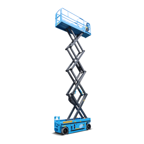
- Page 1 Operation Part No.501042100002 Rev: A Manual Jul 2020 产品说明书 PRODU C T MAN U AL GTJZ0608/0608/2132 GTJZ0808/0808/2732 0608E (2132E) G T JZ 0808E (2732E) G T JZ 0808E (2732E) G T JZ G T JZ 0808E (2732E)
- Page 3 Operating, servicing and maintaining this vehicle or equipment can expose you to chemicals including engine exhaust, carbon monoxide, phthalates, and lead, which are known to the State of California to cause cancer and birth defects or other reproductive harm. To minimize exposure, avoid breathing exhaust, do not idle the engine except as necessary, service your vehicle or equipment in a well-ventilated area and wear gloves or wash your...
- Page 4 : No.128, East Jinzhou Avenue, Ningxiang High-tech Industrial Park, Changsha, Hunan, China Zip Code : 410600 Copyright © Hunan Sinoboom Intelligent Equipment Co., Ltd. All Rights Reserved The final interpretation right of this manual belongs to Hunan Sinoboom Intelligent Equipment Co., Ltd.
- Page 5 APPLICATION Use the following table to identify the specific serial number for models included in this manual. Check the model of your machine before consulting the manual, and then use the correct manual according to the serial number of the model. See the nameplate on your machine to identify the model and serial number.(See 10 Decals/Nameplates Inspection, page 10-1 of the Operation Manual for details.)
- Page 6 This Page Intentionally Left Blank...
- Page 7 This manual covers the basic parts information of one or more products. Therefore, please use this manual according to your needs. If you find problems in the manual or have suggestions for improve- ment, feel free to share your feedback with Sinoboom, and we will address these issues as soon as possible.
- Page 8 This Page Intentionally Left Blank...
-
Page 9: Table Of Contents
TABLE OF CONTENTS Preparing for a Pre-operation Func- Introduction ......iii tion Test ....... 6-1 1 Performance Parameters .. - Page 10 Operating on the Ground....7-3 Appendix 2: Prepare the Work Operating on the Platform... . . 7-3 Record Before Delivery ..
-
Page 11: Introduction
The owner or administrator of the machine shall also provide the manufacturer’s maintenance information to the person responsible for maintaining the machine. If you have any questions, contact Hunan Sinoboom In- telligent Equipment Co., Ltd.. GTJZ0608&0808 Operation Manual © Jul 2020... - Page 12 This Page Intentionally Left Blank © Jul 2020 GTJZ0608&0808 Operation Manual...
-
Page 13: Performance Parameters
PERFORMANCE PARAMETERS Table 1-1 GTJZ0608 Specifications GTJZ0608 (METRIC) 2132 (IMPERIAL) MEASURE DIMENSION PARAMETERS Max. platform height 6.3m 20 ft 8 in. Max. working height 8.3m 27 ft 3 in. Max. horizontal extension 0.9m 3 ft Length 2.46m 8 ft Width 0.83m 2 ft 8.7 in. - Page 14 PERFORMANCE PARAMETERS Table 1-1 GTJZ0608 Specifications (continued) GTJZ0608 (METRIC) 2132 (IMPERIAL) MEASURE Max. allowable manual force (indoor/ 400N(indoor)/200N 90 lbf(indoor)/45 lbf outdoor) (outdoor) (outdoor) Max. noise 72dB POWER PARAMETERS Hydraulic tank capacity 3.3 gal(imperial)/4 gal(US) Hydraulic system capacity (including tank) 3.5 gal(imperial)/4.2 gal(US) Hydraulic system pressure 24MPa...
- Page 15 PERFORMANCE PARAMETERS Table 1-2 GTJZ0808 Specifications (continued) GTJZ0608 (METRIC) 2132 (IMPERIAL) MEASURE Height (stowed, rails up) 2.36m 7 ft 9 in. Wheel base 1.88m 6 ft 2 in. Wheel span 0.64m 2.1 ft Ground clearance (pothole guards 0.1m 4 in. retracted) Ground clearance (pothole guards 25mm...
- Page 16 PERFORMANCE PARAMETERS Table 1-2 GTJZ0808 Specifications (continued) GTJZ0608 (METRIC) 2132 (IMPERIAL) MEASURE ENVIRONMENTAL REQUIREMENT Max. allowable wind speed (indoor only) 0 mph 0m/s Max. allowable altitude 1000m 3280 ft Allowable ambient temperature (lead-acid -10℃ to 40℃ 14℉ to 104℉ batteries) Allowable ambient temperature (lithium -20℃...
-
Page 17: Machine Components
MACHINE COMPONENTS Figure 2-1 GTJZ0608&0808 Operation Manual © Jul 2020... - Page 18 MACHINE COMPONENTS Component Japan China ANSI Korea Poland 1. Fixed Platform √ 2. Foot Switch √ 3. Extended Platform √ 4. Manual Storage √ Container 5. Overhead Protection √ 6. Working Light √ 7. Platform Control Box √ 8. AC Power Socket √...
-
Page 19: Safety
SAFETY Read, understand and comply with the safety rules and NOTICE regulations of your workplace and your government. Indicates a situation that can cause damage to the Before using the machine, obtain proper training on engine, personal property and/or the environment, or safe machine operation and make sure you can safely cause the equipment to operate improperly. -
Page 20: Tipping Hazards And Rated Load
SAFETY Extending: Extension only 120kg(265 lb) GTJZ0808 ELECTRICAL SHOCK HAZARDS Retracting 250kg(551 lb) • Always maintain a safe distance Extending: Stationary only 130kg(287 lb) from power lines and electrical equipment in accordance with ap- Extending: Extension only 120kg(265 lb) plicable government regulations and see Table 3-1 , page 3-2. - Page 21 SAFETY TIPPING HAZARDS TIPPING HAZARDS • On the platform, do not attach an • Personnel, equipment and materi- additional device for placing tools als on the platform must not ex- or other materials to the guardrail. ceed the maximum load capacity. This will increase the platform weight, surface area and load.
-
Page 22: Work Environment Hazards
SAFETY WORK ENVIRONMENT HAZARDS UNSAFE JOBSITE HAZARDS the platform when the wind speed exceeds 12.5 m/s (18 mph). If the wind speed exceeds 12.5 m/s (18 mph) after the platform is lifted, UNSAFE JOBSITE HAZARDS fold the platform and do not continue to operate the machine. -
Page 23: Unsafe Operation Hazards
SAFETY NOTICE UNSAFE OPERATION HAZARDS Maximum climbing ability is suitable for machines with platform retracted. • Do not push any object outside Maximum Slope:25% (14°) the platform. The maximum lateral force allowed is: Climbing capacity means the maximum allowable tilt angle of the machine when it is on solid ground and the platform is only capable of carrying one person. -
Page 24: Fall Hazards
SAFETY UNSAFE OPERATION HAZARDS FALL HAZARDS • Do not tie the platform onto • Each person on the platform must nearby objects. wear harnesses or use safety • Do not put the load outside the equipment consistent with gov- platform. ernment regulations. -
Page 25: Crush Hazards
SAFETY COLLISION HAZARDS COLLISION HAZARDS • Never operate a machine danger- • Pay attention to the field of sight ously or for fun. and the presence of blind spots when moving or operating the machine. • Pay attention to the extended plat- CRUSH HAZARDS form when moving the machine. -
Page 26: Damaged Machine Hazards
SAFETY DAMAGED MACHINE BATTERY HAZARDS HAZARDS NOTICE FIRE AND EXPLOSION HAZARD To avoid machine damage, follow all operation and • Batteries contain sulfuric acid and maintenance requirements in this manual and the generate explosive mixtures of Maintenance Manual. hydrogen and oxygen gases. Keep any device that may cause sparks or flames (including cigarettes/smoking materials) -
Page 27: Charging The Battery
SAFETY NOTICE After charging the battery, be sure that: WELDING HAZARDS • The battery cable connections are free of corrosion. • Comply with the welder manufac- turer’s recommendations for pro- • The battery hold-down and cable connections are cedures concerning proper use of secured. - Page 28 SAFETY This Page Intentionally Left Blank © Jul 2020 3-10 GTJZ0608&0808 Operation Manual...
-
Page 29: Jobsite Inspection
JOBSITE INSPECTION • Unstable or ultra-smooth surfaces • Overhead obstacles and high-voltage wires UNSAFE OPERATION HAZARD • Hazardous locations • Ground surface that could fail to support the ca- Be sure to follow the instructions and pacity of the machine and its load safety rules in this manual. - Page 30 JOBSITE INSPECTION This Page Intentionally Left Blank © Jul 2020 GTJZ0608&0808 Operation Manual...
-
Page 31: Pre-Operation Inspection
PRE-OPERATION INSPECTION the machine has obvious problems before the oper- ator performs a pre-operation function test. • The pre-operation inspection also helps the operator UNSAFE OPERATION HAZARD determine whether the machine requires routine maintenance. Be sure to follow the instructions and •... -
Page 32: Inspecting Parts
PRE-OPERATION INSPECTION • Check battery for leaks and proper liquid level. Add INSPECT HYDRAULIC OIL distilled water as needed. See Inspecting the Bat- LEVEL tery, page 5-2. • Check whether the protective device in use matches the type of work performed and conforms to relevant Ensuring appropriate hydraulic oil is important for prop- technical standards. - Page 33 PRE-OPERATION INSPECTION NOTICE After the battery is fully charged, wear protective gloves for inspection. • Check the acidic liquid level of the lead-acid battery. If needed, refill the distilled water through a filling line above the lead-acid battery. Only add enough distilled water to cover the plate.
- Page 34 PRE-OPERATION INSPECTION This Page Intentionally Left Blank © Jul 2020 GTJZ0608&0808 Operation Manual...
-
Page 35: Pre-Operation Function Test
PRE-OPERATION FUNCTION TEST PREPARING FOR A PRE- OPERATION FUNCTION UNSAFE OPERATION HAZARD TEST Be sure to follow the instructions and safety rules in this manual. Failure to Before beginning a pre-operation function test: follow the instructions and safety rules in this manual may result in 1. -
Page 36: Function
PRE-OPERATION FUNCTION TEST TESTING THE LIFTING AND 9. Backspace Key 1. Insurance LOWERING FUNCTIONS 2. Emergency Stop Button 10. Page Up Key 11. Enabling Key 3. OFF Position 12. Lowering Key 4. Platform Control Position 5. Key Switch 13. Lifting Key 14. -
Page 37: Testing The Emergency Stop
PRE-OPERATION FUNCTION TEST TESTING THE PLATFORM CONTROLLER 1. Push the emergency stop button on the ground controller and platform controller to the ON position. 2. Turn the key switch of the ground controller to the platform control position. TESTING THE EMERGENCY STOP FUNCTION 1. -
Page 38: Testing The Lifting And Lowering
PRE-OPERATION FUNCTION TEST TESTING THE LIFTING AND TESTING THE DRIVING AND LOWERING FUNCTIONS BRAKING FUNCTIONS Lifting Forward Back 1. Press the lifting/lowering button. The button 1. Press the driving and steering button. The button should illuminate. should illuminate. 2. Hold the enabling key on the control handle and 2. -
Page 39: Testing The Emergency Lowering
PRE-OPERATION FUNCTION TEST 6. Press the lifting/lowering button. Hold the enabling key of the control handle and push the control handle reverse to activate the lowering function and lowering it to fully retracted state. 7. Press the walking and steering button, then press the high/low speed button. -
Page 40: Testing The Pothole Guard
PRE-OPERATION FUNCTION TEST drive the machine onto the two boards. The wooden to the level of the fork and leaves the pressure lever boards should measure(L × W × H): 50 mm×100 of the pothole guard. mm×100 mm (2 in.×4 in.×4 in.). 2. -
Page 41: Operating The Machine
OPERATING THE MACHINE Each new operator must perform the pre-operation in- spection, pre-operation function test, and workplace checks before using the machine. UNSAFE OPERATION HAZARD Be sure to follow the instructions and USING THE EMERGENCY safety rules in this manual. Failure to follow the instructions and safety STOP FUNCTION rules in this manual may result in... -
Page 42: Using The Emergency Pull/Drag
OPERATING THE MACHINE When there's an emergency, machine malfunction or 4. Press page down key until the display appears "Ma- power loss need emergency pull/drag, release brake chine Mode", then press the enter button. has the following two methods: 5. Press page down key until the display appears "Break Release", then press the enter button. -
Page 43: Operating On The Ground
OPERATING THE MACHINE 5. At this time the brake is released, force can push NOTICE the machine sliding. Use the platform controller’s color-coded arrow to de- 6. Pull out the reversing valve 1. termine the direction of the wheel rotation. 7. -
Page 44: Operating With The Platform Control
OPERATING THE MACHINE extension platform into the built-in slots, which will OPERATING WITH THE secure the extension platform. PLATFORM CONTROLLER ON THE GROUND UNSAFE OPERATION HAZARD Before operating the machine with the platform control- ler on the ground: Do not stand on the platform exten- 1. -
Page 45: Using The Battery Level Indicator
OPERATING THE MACHINE USING THE BATTERY LEVEL INDICATOR Use the diagnostic reading display on the platform to determine the battery level. Table 7-3 PLATFORM POWER DISPLAY POWER RATIO DESCRIPTION The battery has been fully charged. 90-100% The battery is at 70% of its capacity. The battery is at 50% of its capacity. -
Page 46: Charging The Battery
OPERATING THE MACHINE 2. Remove the ventilation cover of the lead-acid CHARGING THE BATTERY battery. 3. Check the acidic liquid level of the lead-acid battery. If needed, refill the distilled water through a filling line above the lead-acid battery. Only add enough distilled water to cover the plate. - Page 47 OPERATING THE MACHINE 1. Press and hold Select key for 10s, when the display shows EQ in quick flashing, release the key and the charger has been set in EQ mode. 2. To exit the EQ mode, likewise, press and hold the Select key for 10s, when the display shows OFF in quick flashing, release the key and the charger will exit the EQ mode.
- Page 48 OPERATING THE MACHINE This Page Intentionally Left Blank © Jul 2020 GTJZ0608&0808 Operation Manual...
-
Page 49: Transporting And Lifting The Machine
TRANSPORTING AND LIFTING THE MACHINE LIFTING THE MACHINE WITH A FORKLIFT TRANSPORTATION AND LIFTING HAZARD Follow these requirements when lifting the machine by forklift: • Use a forklift or crane with the proper lifting capacity to lift the 1. Make sure the platform extension, controller and machine. -
Page 50: Lifting The Machine With A Crane
TRANSPORTING AND LIFTING THE MACHINE LIFTING THE MACHINE WITH A CRANE Follow these requirements when lifting the machine by crane: 1. Fully lower the platform. Keep the platform down during transportation. 2. Make sure the platform extension, controller and chassis components are stable. 3. - Page 51 TRANSPORTING AND LIFTING THE MACHINE Figure 8-4 GTJZ0608&0808 Operation Manual © Jul 2020...
- Page 52 TRANSPORTING AND LIFTING THE MACHINE This Page Intentionally Left Blank © Jul 2020 GTJZ0608&0808 Operation Manual...
-
Page 53: Maintenance
MAINTENANCE This section provides detailed procedures for regular – Ensure the key switch of the ground controller is maintenance inspections. in the OFF position and remove the key to pre- vent unauthorized use of the machine. – Place the red emergency stop button on the plat- form control box and ground controller in the OFF position to avoid accidental start-up of the UNSAFE OPERATION HAZARD... -
Page 54: Following Amaintenance Schedule
MAINTENANCE 2. Use the following table to note the results. After re-inspected after repair is completed and marked each section is complete, mark the appropriate box. in the box marked "inspection". 3. Record the inspection results. If any inspection re- sults are "NO", the machine must be stopped and Table 9-1 PREPARE THE WORK RECORD BEFORE DELIVERY... - Page 55 MAINTENANCE Table 9-3 REPAIR & INSPECTION REPORT Model Serial No. Checklist A Procedures REPAIRED/Ma- YES/Machine is NO/Machine Has Problem chine Has Been Items in Good Damage or Description Repaired Condition Malfunction A-1 Inspect All Manuals A-2 Inspect All Decals A-3 Inspect Damaged, Loose or Lost Parts A-4 Inspect Hydraulic Oil Level...
- Page 56 MAINTENANCE REPAIR & INSPECTION REPORT REPAIRED/Ma- YES/Machine is NO/Machine Has Problem chine Has Been Items in Good Damage or Description Repaired Condition Malfunction B-1 Inspect Electric Wires B-2 Inspect Rim ,Tire and Fasteners B-3 Inspect Battery B-4 Inspect Hydraulic Oil B-5 Inspect Hydraulic Oil Tank Ventilation System B-6 Inspect Brake Manual...
-
Page 57: Decals/Nameplates Inspection
DECALS/NAMEPLATES INSPECTION Use appropriate inspection methods to check that all decals are easy to identify and properly placed. Replace any lost or damaged safety decals. Clean safety decals with neutral soap and water. Do not use solvent-based cleaners, which can damage safety label materials. - Page 58 GTJZ0608>JZ0808 DECALS/NAMEPLATES(AS) Description Part NO. Remarks Decals-GTJZ0608(AS) 101041103015 Decals-GTJZ0808(AS) 101042103007 101013100004 GTJZ0608 101014100004 GTJZ0808 101046100009 Decal-SINOBOOM 101058103001 Decal-IPAF Decal-Platform electrical plug 101014100007 Decal-Use condition (GTJZ0608) 101016100007 Decal-Use condition (GTJZ0808) 101016100019 Decal-Lifting lugs 101014100020 101014100021 Decal-Tiedown Decal-Tire to ground max. load 1180kg (2601 lb)
- Page 59 DECALS/NAMEPLATES INSPECTION Description Part NO. Remarks Decal-Engage the safety arm 101015100011 Decal-Charging voltage 101014100008 Decal-Use condition (GTJZ0608) 101041103012 Decal-Use condition (GTJZ0808) 101042103005 101014100032 Decal-Serial number Decal-Emergency down 101014100025 101016100035 Decal-Release brake Nameplate-AS 101012100038 215050000012 Blind rivet 4×8-ZnD GB/T 12618.2 101012100027 Decal-Read manuals Decal-Tipping hazard 101012100019...
- Page 60 DECALS/NAMEPLATES INSPECTION 14 15 16 17 12 9 8 12 13 15 14 12 25 26 © Jul 2020 10-4 GTJZ0608&0808 Operation Manual...
- Page 61 GTJZ0608>JZ0808 DECALS/NAMEPLATES(CE-PL) Description Part NO. Remarks Decals-GTJZ0608(CE-PL) 101041103018 Decals-GTJZ0808(CE-PL) 101042103010 101013100004 GTJZ0608 101014100004 GTJZ0808 101046100009 Decal-SINOBOOM Decal-Use condition (GTJZ0608) 101041103012 Decal-Use condition (GTJZ0808) 101042103005 Decal-Platform electrical plug 101014100007 Decal-Engage the safety arm 101015100011 Decal-Lifting lugs 101014100020 101014100021 Decal-Tiedown Decal-Tire to ground max. load 1180kg (2601 lb)
- Page 62 DECALS/NAMEPLATES INSPECTION Description Part NO. Remarks Decal-Main power switch 101016100031 101058103001 Decal-IPAF Decal-Charging voltage 101014100008 Decal-Use condition (GTJZ0608) 101041103013 Decal-Use condition (GTJZ0808) 101042103006 101014100032 Decal-Serial number Decal-Emergency down 101014100025 101016100035 Decal-Release brake Nameplate-CE 101012100037 215050000012 Blind rivet 4×8-ZnD GB/T 12618.2 101012100027 Decal-Read manuals Decal-Tipping hazard...
- Page 63 DECALS/NAMEPLATES INSPECTION 14 15 16 17 12 9 8 12 13 15 25 26 14 12 GTJZ0608&0808 Operation Manual 10-7 © Jul 2020...
- Page 64 GTJZ0608>JZ0808 DECALS/NAMEPLATES(CSA) Description Part NO. Remarks Decals-GTJZ0608(CSA) 101041103023 Decals-GTJZ0808(CSA) 101042103014 101013100004 GTJZ0608 101014100004 GTJZ0808 101046100009 Decal-SINOBOOM 101058103001 Decal-IPAF Decal-Platform electrical plug 101014100007 Decal-Use condition (GTJZ0608) 101041103013 Decal-Use condition (GTJZ0808) 101042103006 Decal-Lifting lugs 101014100020 101014100021 Decal-Tiedown Decal-Tire to ground max. load 1180kg (2601 lb)
- Page 65 DECALS/NAMEPLATES INSPECTION Description Part NO. Remarks Decal-Engage the safety arm 101014100026 Decal-Charging voltage 101014100008 Decal-Use condition (GTJZ0608) 101041103012 Decal-Use condition (GTJZ0808) 101042103005 101014100032 Decal-Serial number Decal-Emergency down 101014100025 101016100035 Decal-Release brake Nameplate-CSA 101048103022 215050000012 Blind rivet 4×8-ZnD GB/T 12618.2 Decal-Tipping hazard 101040100009 Decal-Tipping hazard 101012100019...
- Page 66 DECALS/NAMEPLATES INSPECTION 14 15 16 17 12 9 8 12 13 15 25 26 14 12 © Jul 2020 10-10 GTJZ0608&0808 Operation Manual...
- Page 67 GTJZ0608>JZ0808 DECALS/NAMEPLATES(GB) Description Part NO. Remarks Decals-GTJZ0608(GB) 101041103011 Decals-GTJZ0808(GB) 101042103004 101013100004 GTJZ0608 101014100004 GTJZ0808 101046100009 Decal-SINOBOOM 101014100034 Decal-Contact information Decal-Platform electrical plug 101014100007 Decal-Platform electrical plug 101023100011 Decal-Lifting lugs 101014100020 101014100021 Decal-Tiedown Decal-Tire to ground max. load 1180kg (2601 lb) 101014100019...
- Page 68 DECALS/NAMEPLATES INSPECTION Description Part NO. Remarks Decal-Charging voltage 101014100008 101046100007 Decal-SINOBOOM 101014100032 Decal-Serial number Decal-Emergency down 101014100025 101016100035 Decal-Release brake Nameplate-GB 101017100009 215050000012 Blind rivet 4×8-ZnD GB/T 12618.2 101012100027 Decal-Read manuals Decal-Tipping hazard 101012100019 Decal-Tipping hazard 101012100007 Decal-Use condition (GTJZ0608)
- Page 69 DECALS/NAMEPLATES INSPECTION 14 15 16 17 12 9 8 12 13 15 14 12 GTJZ0608&0808 Operation Manual 10-13 © Jul 2020...
- Page 70 GTJZ0608>JZ0808 DECALS/NAMEPLATES(KCS) Description Part NO. Remarks Decals-GTJZ0608(KCS) 101041103016 Decals-GTJZ0808(KCS) 101042103004 101013100004 GTJZ0608 101014100004 GTJZ0808 101046100009 Decal-SINOBOOM 101058103001 Decal-IPAF Decal-Platform electrical plug 101014100007 Decal-Use condition (GTJZ0608) 101041103013 Decal-Use condition (GTJZ0808) 101042103006 Decal-Lifting lugs 101014100020 101014100021 Decal-Tiedown Decal-Tire to ground max. load 1180kg (2601 lb)
- Page 71 DECALS/NAMEPLATES INSPECTION Description Part NO. Remarks Decal-Engage the safety arm 101015100011 Decal-Charging voltage 101014100008 Decal-Use condition (GTJZ0608) 101041103012 Decal-Use condition (GTJZ0808) 101042103005 101014100032 Decal-Serial number Decal-Emergency down 101014100025 101016100035 Decal-Release brake Nameplate-KCS 101015100026 215050000012 Blind rivet 4×8-ZnD GB/T 12618.2 101012100027 Decal-Read manuals Decal-Tipping hazard 101012100019...
- Page 72 DECALS/NAMEPLATES INSPECTION 14 15 16 17 12 9 12 13 15 14 12 25 26 © Jul 2020 10-16 GTJZ0608&0808 Operation Manual...
- Page 73 GTJZ0608>JZ0808 DECALS/NAMEPLATES(CE) Description Part NO. Remarks Decals-GTJZ0608(CE) 101041103014 Decals-GTJZ0808(CE) 101042103003 101013100004 GTJZ0608 101014100004 GTJZ0808 101046100009 Decal-SINOBOOM 101058103001 Decal-IPAF Decal-Platform electrical plug 101014100007 Decal-Use condition (GTJZ0608) 101041103013 Decal-Use condition (GTJZ0808) 101042103006 Decal-Lifting lugs 101014100020 101014100021 Decal-Tiedown Decal-Tire to ground max. load 1180kg (2601 lb)
- Page 74 DECALS/NAMEPLATES INSPECTION Description Part NO. Remarks Decal-Engage the safety arm 101040100010 Decal-Charging voltage 101014100008 Decal-Use condition (GTJZ0608) 101041103012 Decal-Use condition (GTJZ0808) 101042103005 101014100032 Decal-Serial number Decal-Emergency down 101014100025 101016100035 Decal-Release brake Nameplate-CE 101012100037 215050000012 Blind rivet 4×8-ZnD GB/T 12618.2 101012100027 Decal-Read manuals Decal-Tipping hazard 101012100019...
- Page 75 DECALS/NAMEPLATES INSPECTION 14 15 16 17 12 9 8 12 13 15 25 26 14 12 GTJZ0608&0808 Operation Manual 10-19 © Jul 2020...
- Page 76 DECALS/NAMEPLATES INSPECTION GTJZ0808 DECALS/NAMEPLATES(ANSI) Description Part NO. Remarks Decals-GTJZ0808(ANSI) 101041103019 101014100004 GTJZ0808 101046100009 Decal-SINOBOOM Decal-Use condiion(GTJZ0808) 101042103011 Decal-Platform electrical plug 101014100007 Decal-Engage the safety arm 101014100026 Decal-Lifting lugs 101014100020 101014100021 Decal-Tiedown Decal-Tire to ground max. load 1180kg (2601 lb) 101048103017...
- Page 77 DECALS/NAMEPLATES INSPECTION Description Part NO. Remarks 101014100032 Decal-Serial number Decal-Emergency down 101014100025 101016100035 Decal-Release brake Nameplate-ANSI 101048103010 215050000012 Blind rivet 4×8-ZnD GB/T 12618.2 101012100027 Decal-Read manuals Decal-Tipping hazard 101012100019 Decal-Tipping hazard 101012100007 101040103014 Decal-Detachable bracket Decal-Annual inspection 101040103015 GTJZ0608&0808 Operation Manual 10-21 ©...
- Page 78 DECALS/NAMEPLATES INSPECTION 14 15 16 17 12 9 12 13 15 25 26 14 12 © Jul 2020 10-22 GTJZ0608&0808 Operation Manual...
-
Page 79: Appendix 1: Symbols And Description
APPENDIX 1: SYMBOLS AND DESCRIPTION SYMBOLS CHART Read maintenance Anchor point allows Close the chassis door Press the change Repeatedly move man- manual only 1 person to tie valve ual brake release valve Wind speed Chemical burns Wedge the wheel Release the brake Wind hazards... - Page 80 DECALS/NAMEPLATES INSPECTION Tip-over hazards- Tip-over hazards- Tip-over hazards- Tip-over hazards- Tip-over hazards- Never use machine Never use machine Never leave chassis Never push or pull ob- Never suspend objects during strong, gusty during strong, gusty door open jects outside platform from platform wind wind...
- Page 81 DECALS/NAMEPLATES INSPECTION Forklift fork position Platform carrying Carrying capacity of Hydraulic oil filler Horn capacity fixed and extended platform Tool or weight Fast/high speed Slow/low speed GTJZ0608&0808 Operation Manual © Jul 2020...
- Page 82 DECALS/NAMEPLATES INSPECTION This Page Intentionally Left Blank © Jul 2020 GTJZ0608&0808 Operation Manual...
-
Page 83: Appendix 2: Prepare The Work Record Before Delivery
APPENDIX 2: PREPARE THE WORK RECORD BEFORE DELIVERY PREPARE THE WORK RECORD BEFORE DELIVERY Model Serial No. REPAIRED/Machine YES/Machine is in NO/Machine Has Damage Inspection Item Has Been Repaired Good Condition or Malfunction Pre-operational Inspection Maintenance Procedure Functional Inspection Machine Buyer/ Renter Inspector Signature Inspector Title Inspector Company... - Page 84 DECALS/NAMEPLATES INSPECTION This Page Intentionally Left Blank © Jul 2020 GTJZ0608&0808 Operation Manual...
-
Page 85: Appendix 3: Repair & Inspection Report
APPENDIX 3: REPAIR & INSPECTION REPORT REPAIR & INSPECTION REPORT Model Serial No. Checklist A Procedures REPAIRED/Ma- YES/Machine is NO/Machine Has Problem chine Has Been Items in Good Damage or Description Repaired Condition Malfunction A-1 Inspect All Manuals A-2 Inspect All Decals A-3 Inspect Damaged, Loose or Lost Parts A-4 Inspect Hydraulic Oil... - Page 86 DECALS/NAMEPLATES INSPECTION REPAIR & INSPECTION REPORT A-18 Perform Maintenance After 30 Days Checklist B Procedures REPAIRED/Ma- YES/Machine is NO/Machine Has Problem chine Has Been Items in Good Damage or Description Repaired Condition Malfunction B-1 Inspect Electric Wires B-2 Inspect Rim ,Tire and Fasteners B-3 Inspect Battery B-4 Inspect Hydraulic Oil...
- Page 87 DECALS/NAMEPLATES INSPECTION REPAIR & INSPECTION REPORT Inspector Title Inspector Company NOTES: 1. The Repair & Inspection Report shall include the inspection table of each regular inspection. 2. Duplicate the Repair & Inspection Report for each inspection. Store the completed tables for 10 years or until the machine is no longer in use or as required by machine owner/company/custodian.
- Page 88 Solution s Alw ays For B et t er A ccess Solution s Always for Better Access Solutions AS/N ZS Hunan Sinoboom Intelligent Equipment Co., Ltd. 长沙市宁乡高新技术产业园区金洲大道东 128 号 No.128, East Jinzhou Avenue, Ningxiang High-tech Industrial Park, Changsha, Hunan, China 市宁乡高新技术产业园区金洲大道东...
Need help?
Do you have a question about the GTJZ2132 and is the answer not in the manual?
Questions and answers