Advertisement
Quick Links
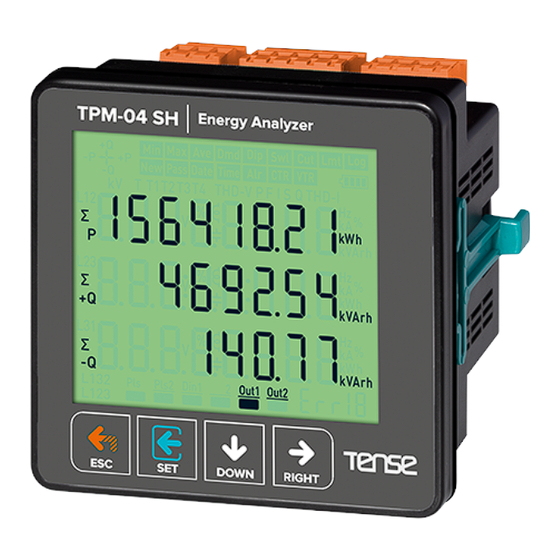
TPM-04 SH
USER MANUAL
Measures up to voltage harmonics 31st.
Measures up to current harmonics 31st.
Supports 3P4W connections.
RS485 Modbus RTU
71.5 x 61.5 Custom Design Glass LCD
It shows the powers of each phas e (P1, P2, P3).
It shows the reactive powers of each phas e (Q1,Q2,Q3inductive and capacitive).
It shows the apparent powers of each phas e (S1,S2, S3).
It shows power factors (PF) and cosφ values of each phases.
It shows the min., max. and ave. values of the phase-to-phase and phase-neutral voltages.
It shows the values of each phase (I1, I2, I3).
It shows total import and export active ( Σ kWh) energy.
It shows total inductive and capacitive reactive ( Σ kVArh) energy.
1x Digital Input
2x Relay output (adjustable).
It shows voltage and current irregularity.
It show demands.
You can delete energies and demands.
The menu is password protected.
Tense Electric - Electronic
MADE IN TURKEY
Advertisement

Related Manuals for Tense TPM-04 SH


Summary of Contents for Tense TPM-04 SH
- Page 1 It shows total inductive and capacitive reactive ( Σ kVArh) energy. 1x Digital Input 2x Relay output (adjustable). It shows voltage and current irregularity. It show demands. You can delete energies and demands. The menu is password protected. Tense Electric - Electronic MADE IN TURKEY...
-
Page 2: Connection Diagrams
1 - ConnectionDiagrams: Figure-1 COM NO OUT2 OUT1 DIGITAL 85-240VAC RS485 5A/250VAC 5A/250VAC INPUT 50/60Hz.<6VA CurentTransformerConnections VoltageInputs Load Figure-1: 3P4Wconnection type: 3 phase current and 3 phase voltage and neutral. - Page 3 2 - Matters to be consideredin current transformer selection and connection Note that the value of current transformer is higher than the maximum current drawn from the system. It is advisible that the class of the current transformer (it can be written class, klas, cl, kl) is 0.5. To avoidthe complexity when connecting the current transformer output terminal use different colour cables or give cable numbers.
- Page 4 7- Introduction of Screen: New Pass Time CTR VTR THD-V PFIS Q THD-I Σ kVArh Σ kVArh Σ kVArh Din1 Out1 Out2 Figure-2 1 - Indicates the unit of the value. 2 - Indicates which phase the value belongs to . 3 - Indicates displayed values.
- Page 5 8- Introduction of Buttons: Press this button while in menu to exit the menu without savingthe values. ESC: When this key is pressed while not in the menu, the screen always shows figure-3. This button enters menu/parameter. It records the changesof parameters and remove SET: from parameter.
- Page 6 9 - Progress OnScreen Information: Din1 Out1 Out2 Din1 Out1 Out2 Din1 Out1 Out2 Din1 Out1 Out2 Figure-3 Figure-4 Figure-5 Figure-6 Figure-3: Shows phase-neutral voltage. When you press right button, the figure-4 appears on the screen. Figure-4: Shows minimum(Min) voltage values of phase-neutral voltage. When you press right button, the figure-5 appears on the screen.
- Page 7 kVAr kVAr kVAr kVAr kVAr kVAr Din1 Out1 Out2 Din1 Out1 Out2 Figure-15 Figure-16 Figure-15: Shows the reactive power value(Q)values for each phase. When you press the right button, figure-16 appears on the screen. Figure-16: Shows the active power(Q) demand(Dmd) values for each phase. When you press the right button, figure-17 appears on the screen.
- Page 8 THD-I THD-I Σ Σ kVArh Σ kVArh Din1 Out1 Out2 Din1 Out1 Out2 Din1 Out1 Out2 Figure-24 Figure-25 Figure-26 Figure-24: Shows the total current harmonic distortion value(THD-I)values for each phase. When you press the right button, figure-25 appears on the screen. Figure-25: Current harmonics values of up to 31st harmonics are displayed on each screen, with 3 values per screen.
- Page 9 10 - Fast Forwarding of Screen Information: Din1 Out1 Out2 Din1 Out1 Out2 Din1 Out1 Out2 Din1 Out1 Out2 Figure-3 Figure-7 Figure-11 Figure-13 When the device is energised, figure-3 is displayed. When you press the down button, figure-7 is displayed. When you press the down button, figure-11 is displayed.
-
Page 10: Menu Structure
11 - MenuStructure: Figure-33 Din1 Out1 Out2 Din1 Out1 Out2 Figure-32 Din1 Out1 Out2 Din1 Out1 Out2 Din1 Out1 Out2 Figure-40 Figure-34 Figure-35 When you press the right button while the figure-32 is on screen, figure-33 password inquiry is displayed on the screen. - Page 11 12 - Setting the Current Transformer Ratio: To changethe current transformer ratio, press the set button while the figure-34 is on the screen. Figure-41 comes to the screen. Press right button to move between digits. Press the down key to change the value of the digit. You can change the digit value which is the underline.
- Page 12 16- Enter PasswordValue: In order to change password; press set button while Figure-38 is on the screen. The Figure-45 comes to the screen. In order to pass through steps; press the button on the right. In order to change the value of the step press the ''down'' button.
- Page 13 18 - Menu Values Table: Parameter Factory Minimum Maximum Parameter Unit Number Value Value Value Current Transformer Ratio 5000 Voltage Transformer Ratio 999.0 Baudrate 9600 1200 38400 Stop bits Data bits Parity none None, Even, Odd ModBus ID Deleting Total Energy Deleting Demand Values PASS Password...
-
Page 14: Technical Specifications
22 - ContactInformation: Muratpaşa Mah. Uluyol Cad. Energy and İşkent Sanayi Sitesi, E-Blok, 1.Kat Compensation BAYRAMPAŞA/ İSTANBUL / TÜRKİYE Tracking System Tel: 0212 578 04 38 - 48 | Fax: 0212 578 04 36 www.tenseenerji.com www.tense.com.tr www.tense.com.tr info@tense.com.tr info@tense.com.tr -13-...
Need help?
Do you have a question about the TPM-04 SH and is the answer not in the manual?
Questions and answers