Table of Contents
Advertisement
Quick Links
Advertisement
Table of Contents

Related Manuals for MQ Power ULTRASILENT Series


Summary of Contents for MQ Power ULTRASILENT Series
- Page 1 OPERATION MANUAL ULTRASILENT™ SERIES MODEL DCA45USI 60Hz GENERATOR (PARTS LIST NO. M187140000B) Revision #4 (03/19/24) To find the latest revision of this publication or associated parts manual, visit our website www.mqpower.com THIS MANUAL MUST ACCOMPANY THE EQUIPMENT AT ALL TIMES.
- Page 2 PAGE 2 — DCA-45USI — OPERATION MANUAL (STD) — REV. #4 (03/19/24)
- Page 3 NOTE PAGE DCA-45USI — OPERATION MANUAL (STD) — REV. #4 (03/19/24) — PAGE 3...
-
Page 4: Table Of Contents
TABLE OF CONTENTS MQ POWER DCA-45USI MQ POWER DCA-45USI MQ POWER DCA-45USI MQ POWER DCA-45USI MQ POWER DCA-45USI AC GENERA AC GENERA AC GENERATOR AC GENERA AC GENERA Here's How To Get Help ..........3 DCA-45USI Specifications .......... 6 Dimensions ..............7 Safety Message Alert Symbols ....... - Page 5 NOTE PAGE DCA-45USI — OPERATION MANUAL (STD) — REV. #4 (03/19/24) — PAGE 5...
-
Page 6: Dca-45Usi Specifications
DCA-45USI — SPECIFICATIONS t a r i f i o i t i v l e i f , d l l e s a l i t r o t i t c r a t h t i l a r a t l a t l... -
Page 7: Dimensions
DCA-45USI — DIMENSIONS (SIDE AND FRONT) Figure 1. Dimensions DCA-45USI — OPERATION MANUAL (STD) — REV. #4 (03/19/24) — PAGE 7... -
Page 8: Safety Message Alert Symbols
NOTE instructions for the safe and efficient operation of the MQ Power Model DCA45USI ULTRA-SILENT™ GENERATOR. Explosive Fuel Before using this GENERATOR, ensure that the operating... - Page 9 DCA-45USI — SAFETY MESSAGE ALERT SYMBOLS Accidental Starting Respiratory Hazard ALWAYS place the engine ON/OFF switch in the OFF position, when the trowel is not ALWAYS wear approved respiratory protection. in use. Over Speed Conditions Sight and Hearing hazard NEVER tamper with the factory settings of the engine governor or settings.
-
Page 10: Rules For Safe Operation
■ NEVER use accessories or attachments, which are not is being transfer to a load. recommended by MQ Power for this equipment. Damage to ■ NEVER use a defective or frayed power cable. Check the the equipment and/or injury to user may result. - Page 11 DCA-45USI — RULES FOR SAFE OPERATION ■ ALWAYS make sure that electrical circuits are properly DANGER DANGER: DANGER DANGER DANGER grounded per the National Electrical Code (NEC) and local codes before operating generator. Severe injury or death! by electrocution can result from operating an ungrounded generator.
- Page 12 DCA-45USI — RULES FOR SAFE OPERATION Battery ■ NEVER run engine without air filter. Severe engine damage may occur. The battery contains acids that can cause injury to the eyes and skin. To avoid eye irritation, always wear safety glasses. ■...
-
Page 13: Towing Safety Precautions
DCA-45USI — RULES FOR SAFE OPERATION ■ Avoid sharp turns. Towing Safety Precautions ■ Trailer should be adjusted to a level position at all times CAUTION: CAUTION: CAUTION: CAUTION: CAUTION: when towing. ■ Raise and lock trailer wheel stand in up position when Conform to Department of Transportation transporting. - Page 14 DCA-45USI — INSTALLATION Figure 2. Typical Generator Grounding Application PAGE 14 — DCA-45USI — OPERATION MANUAL (STD) — REV. #4 (03/19/24)
- Page 15 DCA-45USI — INSTALLATION Generator Grounding Outdoor Installation To guard against electrical shock and possible damage to Install the generator in a clear area. Make sure the generator the equipment, it is important to provide a good EARTH is on secure level ground so that it cannot slide or shift ground.
- Page 16 DCA-45USI — TOWING SAFETY PRECAUTIONS ■ ALWAYS attach trailer’s safety chain to bumper of towing Towing Safety Precautions vehicle. CAUTION CAUTION CAUTION CAUTION: CAUTION ■ ALWAYS make sure the vehicle and trailer directional, Check with your local county or state safety backup, brake, and trailer lights are connected and towing regulations before towing your working properly.
-
Page 17: Trailer Specifications
DCA-45USI — TRAILER SPECIFICATIONS CAUTION CAUTION CAUTION: 5. Frame Width - Measurement is from fender to fender CAUTION CAUTION 6. Jack Stand - Trailer support device with maximum pound ALWAYS make sure the trailer is in good requirement from the tongue of the trailer. operating condition. -
Page 18: Generator Decals
DCA-45USI — GENERATOR DECALS The DCA-45USI generator is equipped with a number of safety decals. These decals are provided for operator safety and maintenance information. The illustration below and on the preceding page show the decals as they appear on the machine. - Page 19 DCA-45USI — GENERATOR DECALS DCA-45USI — OPERATION MANUAL (STD) — REV. #4 (03/19/24) — PAGE 19...
-
Page 20: General Information
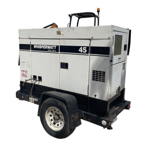
Generator " Open-Delta " excitation system. The open delta system consist of The MQ Power Model DCA-45USI (Figure 4) is a 36 kW an electrically independent winding wound among stationary generator that is designed as a high quality portable (requires windings of the AC output section. - Page 21 DCA-45USI — MAJOR COMPONENTS t a r r o j f f u r e l y l b y l b r i A y l b r o t y l b y l b y l b e t t y l b Figure 4.
- Page 22 DCA-45USI — GENERATOR CONTROL PANEL Figure 5. Generator Control Panel Located behind the generator control panel is the Generator The definitions below describe the controls and functions of Control Box . This box contains some of the necessary the DCA-45USI " Generator Control Panel " (Figure 5). electronic components required to make the generator Main Circuit Breaker –...
- Page 23 DCA-45USI — ENGINE OPERATING PANEL The definitions below describe the controls and functions of the DCA-45USI " Engine Operating Panel " (Figure 6). Panel Light - Normally used in dark places or at night. When activated, panel will luminate. When the generator is not in use, turn the panel light switch to the OFF position.
- Page 24 DCA-45USI — OUTPUT TERMINAL PANEL FAMILIARIZATION Output Terminal Panel Output Terminal Familiarization The Output Terminal Panel (Figure 7) shown below is located The “ Output Terminal Panel ” (Figure 7) is provided with the on the right-hand side (left from control panel) of the generator. following: Lift up on the cover to gain access to receptacles and terminal ...
- Page 25 DCA-45USI — OUTPUT TERMINAL PANEL FAMILIARIZATION 120 VAC GFCI Receptacles Each auxilliary receptacle is protected by a 50 amp circuit breaker. These breakers are located directly above the GFCI There are two 120 VAC, 20 amp GFCI (Duplex Nema 5-20R) receptacles.
- Page 26 DCA-45USI — OUTPUT TERMINAL PANEL FAMILIARIZATION Connecting Loads Blower Fan Loads can be connected to the generator by using the Output This unit has an intake fan located at the rear of the machine Terminal Lugs or the convienience receptacles to draw outside air into the cabinet to cool the engine.
-
Page 27: Load Application
DCA-45USI — LOAD APPLICATION Single Phase Load Three Phase Load When calculating the power requirements for 3-phase power Always be sure to check the nameplate on the generator and equipment to insure the wattage, amperage, frequency, use the following equation: and voltage requirements are satisfactorily supplied by the generator for operating the equipment. - Page 28 DCA-45USI — GENERATOR OUTPUTS Voltage Selector Switch Generator Amperage The voltage selector switch (Figure 15) is located above Table 7 describes the generator’s current output capability the UVWO Hard Wire Hook-up Panel. It has been provided for both 1Ø-phase and 3Ø phase applications. for ease of voltage selection.
-
Page 29: Gauge Reading
DCA-45USI — GAUGE READING How to Read the Output Terminal Gauges. Reading Amperage The gauges and selector switches on the control panel To determine the amperage at a terminal lug, set the DO NOT effect the generator output. They are provided to AC Ammeter Change-Over Switch to the appropriate setting (Figure 19) to activate the AC Ammeter Gauge help observe how much power is being supplied at the Out-... - Page 30 DCA-45USI — OUTPUT TERMINAL PANEL CONNECTIONS 3Ø 208V/1Ø120V Output Terminal Lug Voltages UVWO Terminal Output Voltages Various output voltages can be obtained using the using the 1. Place the voltage selector switch in the 3Ø 240/139 Output Terminal Lugs . The voltages at the terminals are position as shown in Figure 24.
- Page 31 DCA-45USI — OUTPUT TERMINAL PANEL CONNECTIONS 3Ø 480/277 Output Terminal Lug Voltages 1Ø 240V/120V Output Terminal Lug Voltages 1. Place the voltage selector switch in the 3Ø 480/277 1. Place the voltage selector switch in the 1Ø 240/120 position as shown in Figure 26. position as shown in Figure 28.
- Page 32 DCA-45USI — PRE-SETUP Fuel Check Circuit Breakers DANGER: DANGER: DANGER: DANGER: DANGER: To protect the generator from an overload, a 3-pole, 110 amp, main circuit breaker is provided to protect the UVW output Fuel spillage on a hot! engine can cause a terminals from overload.
- Page 33 DCA-45USI — PRE-SETUP Refueling Procedure: Open cabinet doors on the generator. Locate and remove the fuel tank cap and fill tank (Figure 33). DANGER: DANGER: DANGER: DANGER: DANGER: Diesel fuel and its vapors are dangerous to your health and the surrounding environment. Avoid skin contact and/or inhaling fumes.
- Page 34 DCA-45USI — PRE-SETUP Coolant (Ethylane Glycol [Green] / Water — 50/50 mix) Use only drinkable tap water. If hard water or water with When the antifreeze is mixed with NOTE many impurities is used, the inside of the engine and radiator water, the antifreeze mixing ratio may become coated with deposits and cooling efficiency must be less than 50%.
- Page 35 DCA-45USI — PRE-SETUP Battery When connecting battery do the following: This unit is of negative ground DO NOT connect in reverse. 1. NEVER connect the battery cables to the battery Always maintain battery fluid level between the specified terminals when the ignition switch is in the PRE-HEAT/ marks.
-
Page 36: Generator Start-Up Procedure
DCA-45USI — GENERATOR START-UP PROCEDURE 3. Close all engine enclosure doors (Figure 40). WARNING: WARNING: WARNING: WARNING: WARNING: The engine's exhaust contains harmful emissions. ALWAYS have adequate ventilation when operating . Direct exhaust away from nearby personnel. Before Starting CAUTION: Figure 40. - Page 37 DCA-45USI — GENERATOR START-UP PROCEDURE 6. Turn the ignition key to the START position (Figure 44). 9. The generator's voltage meter (Figure 46) displays the Once the engine starts, release the ignition key and output voltage in VOLTS. allow it to return to the PRE-HEAT/RUN position (Figure 42).
- Page 38 DCA-45USI — GENERATOR START-UP PROCEDURE 15. Turn the main , GFCI , and aux . circuit breakers to the 12. The engine oil pressure gauge (Figure 49) will indicate ON position (Figure 52). the oil pressure of the engine. Under normal operating conditions the oil pressure is approximately Figure 49.
-
Page 39: Generator Shut-Down Procedure
DCA-45USI — GENERATOR SHUT-DOWN PROCEDURE Emergency Shut-down Procedure Normal Shut-down Procedure 1. To shut-down the engine in the event of an emergency, To shutdown the generator, use the following procedure: switch the MAIN , GFCI and LOAD (Figure 54) circuit 1. - Page 40 DCA-45USI — MAINTENANCE s l e r i A e t t d i c l e v t l e i t i d s l e r o f s t r e t l i o t t l i F r e t r e t...
- Page 41 DCA-45USI — MAINTENANCE CAUTION: CAUTION: CAUTION: CAUTION: CAUTION: Air Removal If air enters the fuel injection system of a diesel engine, Allow engine to cool when flushing out starting becomes impossible. After running out of fuel, or radiator. Flushing the radiator while hot could after disassembling the fuel system, bleed the system cause serious burns according to the following procedure.
-
Page 42: Trailer Brakes Maintenance
DCA-45USI — TRAILER BRAKES MAINTENANCE Brakes Hydraulic Surge Brakes Trailer brakes should be inspected the first 200 miles of Hydraulic surge brakes (Figure 56) should not require any operation. This will allow the brake shoes and drums to seat special attention with the exception of routine maintenance properly. - Page 43 DCA-45USI — TRAILER MAINTENANCE Suspension Tires/Wheels/Lug Nuts The leaf suspension springs and associated components Tires and wheels are a very important and critical (Figure 57) should be visually inspected every 6,000 miles components of the trailer. When specifying or replacing the for signs of excessive wear, elongation of bolt holes, and trailer wheels it is important the wheels, tires, and axle are loosening of fasteners.
- Page 44 DCA-45USI — TRAILER MAINTENANCE Lug Nut Torque Requirements It is extremely important to apply and maintain proper wheel mounting torque on the trailer. Be sure to use only the fasteners matched to the cone angle of the wheel. Proper procedure for attachment of the wheels is as follows: 1.
-
Page 45: Trailer Wiring Diagram
DCA-45USI — TRAILER WIRING DIAGRAM Figure 59. Trailer/Towing Vehicle Wiring Diagram DCA-45USI — OPERATION MANUAL (STD) — REV. #4 (03/19/24) — PAGE 45... -
Page 46: Engine Wiring Diagram
DCA-45USI — ENGINE WIRING DIAGRAM Figure 60. Engine Wiring Diagram PAGE 46 — DCA-45USI — OPERATION MANUAL (STD) — REV. #4 (03/19/24) - Page 47 DCA-45USI — ENGINE WIRING DIAGRAM Figure 60. Engine Wiring Diagram(Continued) DCA-45USI — OPERATION MANUAL (STD) — REV. #4 (03/19/24) — PAGE 47...
-
Page 48: Generator Wiring Diagram
DCA-45USI — GENERATOR WIRING DIAGRAM Figure 61. Generator Wiring Diagram PAGE 48 — DCA-45USI — OPERATION MANUAL (STD) — REV. #4 (03/19/24) - Page 49 DCA-45USI — TROUBLESHOOTING (GENERATOR) Practically all breakdowns can be prevented by proper handling and maintenance inspections, but in the event of a breakdown, use the table (Table 19) shown below for basic Generator Troubleshooting. If the problem cannot be remedied, consult our company's business office or service plant.
- Page 50 © COPYRIGHT 2024, MULTIQUIP INC. Multiquip Inc , the MQ logo and the MQ Power logo are registered trademarks of Multiquip Inc. and may not be used, reproduced, or altered without written permission. All other trademarks are the property of their respective owners and used with permission.
Need help?
Do you have a question about the ULTRASILENT Series and is the answer not in the manual?
Questions and answers