Table of Contents
Advertisement
Quick Links
Advertisement
Table of Contents
Troubleshooting

Related Manuals for MQ Power DCA40SSKU4F


Summary of Contents for MQ Power DCA40SSKU4F
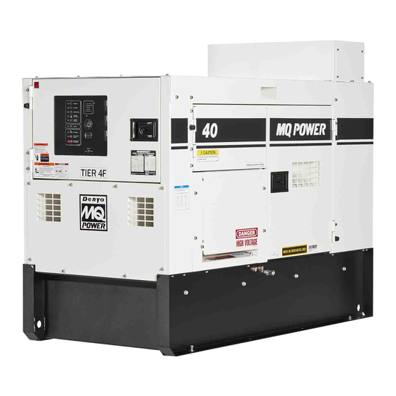
- Page 1 OPERATION MANUAL WHISPERWATT™ SERIES MODEL DCA40SSKU4F 60Hz Generator (KUBOTA V2403-CR-T DIESEL ENGINE) Revision #0 (03/02/18) To find the latest revision of this publication, visit our website at: www.mqpower.com THIS MANUAL MUST ACCOMPANY THE EQUIPMENT AT ALL TIMES.
-
Page 2: Proposition 65 Warning
PROPOSITION 65 WARNING Diesel engine exhaust and some of PAGE 2 — DCA40SSKU4F 60 HZ GENERATOR • OPERATION MANUAL — REV. #0 (03/02/18) -
Page 3: Reporting Safety Defects
1-888-327-4236 (TTY: 1-800-424-9153), go to http://www.nhtsa.dot.gov; or write to: Administrator NHTSA 1200 New Jersey Avenue S.E. Washington, DC 20590 You can also obtain information about motor vehicle safety from http://www.safecar.gov. DCA40SSKU4F 60 HZ GENERATOR • OPERATION MANUAL — REV. #0 (03/02/18) — PAGE 3... -
Page 4: Table Of Contents
Engine Wiring Diagram .......... 51 Battery Charger Wiring Diagram ......52 Engine Block Heater Wiring Diagram ....53 NOTICE Specifications are subject to change without notice. PAGE 4 — DCA40SSKU4F 60 HZ GENERATOR • OPERATION MANUAL — REV. #0 (03/02/18) -
Page 5: Safety Labels
Serious injury or death may result without this servicing. See instruction manual for transfer switch. details. M92010050 This machine stops and starts automatically and without notice. M92010060 Figure 1. Safety Decals DCA40SSKU4F 60 HZ GENERATOR • OPERATION MANUAL — REV. #0 (03/02/18) — PAGE 5... -
Page 6: Safety Information
COULD result in DEATH or SERIOUS INJURY. CAUTION Indicates a hazardous situation which, if not avoided, COULD result in MINOR or MODERATE INJURY. NOTICE Addresses practices not related to personal injury. PAGE 6 — DCA40SSKU4F 60 HZ GENERATOR • OPERATION MANUAL — REV. #0 (03/02/18) - Page 7 „ ALWAYS store generator properly when it is not being used. Generator should be stored in a clean, dry location out of the reach of children and unauthorized personnel. DCA40SSKU4F 60 HZ GENERATOR • OPERATION MANUAL — REV. #0 (03/02/18) — PAGE 7...
- Page 8 „ NEVER touch the hot exhaust manifold, local Health and Safety Administrator. muffl er or cylinder. Allow these parts to cool before servicing generator. PAGE 8 — DCA40SSKU4F 60 HZ GENERATOR • OPERATION MANUAL — REV. #0 (03/02/18)
- Page 9 „ NEVER insert any objects into the output receptacles during operation. This is extremely dangerous. The possibility exists of electrical shock, electrocution or death. DCA40SSKU4F 60 HZ GENERATOR • OPERATION MANUAL — REV. #0 (03/02/18) — PAGE 9...
- Page 10 The battery contains combustible gases and liquids. If these gases and liquids come into contact with a fl ame or spark, an explosion could occur. PAGE 10 — DCA40SSKU4F 60 HZ GENERATOR • OPERATION MANUAL — REV. #0 (03/02/18)
- Page 11 Recyclers and manufacturers alike promote the process of recycling metal. Using a metal recycling center promotes energy cost savings. DCA40SSKU4F 60 HZ GENERATOR • OPERATION MANUAL — REV. #0 (03/02/18) — PAGE 11...
-
Page 12: Specifications
1.7 gal. (6.4 L)/hr at 3/4 load Fuel Consumption 1.2 gal. (4.4 L)/hr at 1/2 load 0.8 gal. (2.9 L)/hr at 1/4 load Battery 27 (CCA 0° 800A) x 1 PAGE 12 — DCA40SSKU4F 60 HZ GENERATOR • OPERATION MANUAL — REV. #0 (03/02/18) -
Page 13: Dimensions
Reference Dimension in. (mm) Reference Letter Dimension in. (mm) Letter 24.88 (632) 25.51 (648) 24.88 (632) 76.38 (1,940) 25.51 (648) 62.20 (1,580) 32.28 (820) 37.40 (950) DCA40SSKU4F 60 HZ GENERATOR • OPERATION MANUAL — REV. #0 (03/02/18) — PAGE 13... -
Page 14: Installation
GENERATOR GROUND LUG GROUND ROD FOR EARTH GROUND. CONNECT TO BUILDING GROUND CABLE GROUND IF APPLICABLE REFERENCE NEC 250-83 (C) Figure 3. Typical Generator Grounding Application PAGE 14 — DCA40SSKU4F 60 HZ GENERATOR • OPERATION MANUAL — REV. #0 (03/02/18) - Page 15 They electrical system, ALWAYS consult with a licensed are there to resist damage to the bottom of the generator electrician. and to maintain alignment. DCA40SSKU4F 60 HZ GENERATOR • OPERATION MANUAL — REV. #0 (03/02/18) — PAGE 15...
-
Page 16: General Information
±.25%. „ Two 125 VAC output receptacles, (GFCI), 20 amps „ Two duplex circuit breakers, 125V@ 20 amps „ Five output terminal lugs (3Ø power) PAGE 16 — DCA40SSKU4F 60 HZ GENERATOR • OPERATION MANUAL — REV. #0 (03/02/18) -
Page 17: Major Components
Coolant Drain Plug Output Terminal Panel Assembly Generator Assembly Lifting Hook Battery Engine Control Panel Assembly Figure 4. Major Components Generator Control Panel Assembly Load Bank DCA40SSKU4F 60 HZ GENERATOR • OPERATION MANUAL — REV. #0 (03/02/18) — PAGE 17... -
Page 18: Engine Control Panel
ON to notify that the DPF regeneration is required to reduce the increased soot levels. Regeneration Start Pushbutton — Press this button to manually start the regeneration process. PAGE 18 — DCA40SSKU4F 60 HZ GENERATOR • OPERATION MANUAL — REV. #0 (03/02/18) - Page 19 D. Overspeed Shutdown — Indicates the engine is running at an unsafe speed. This is considered a major fault. E. Engine Running — Indicates that engine is running at a safe operating speed. DCA40SSKU4F 60 HZ GENERATOR • OPERATION MANUAL — REV. #0 (03/02/18) — PAGE 19...
-
Page 20: Generator Control Panel
To restore power to the output terminal panel, press only. the reset button on the overcurrent relay and place the main circuit breaker in the closed position (ON). PAGE 20 — DCA40SSKU4F 60 HZ GENERATOR • OPERATION MANUAL — REV. #0 (03/02/18) -
Page 21: Output Terminal Panel Familiarization
FOR GFCI RECEPTACLES 120 VAC, 20 AMP GFCI RECEPTACLES RECEPTACLE CIRCUIT BREAKER PANEL CS-6369 TWIST-LOCK AUX. POWER RECEPTACLES 240/120V, 50 AMPS Figure 7. Output Terminal Panel DCA40SSKU4F 60 HZ GENERATOR • OPERATION MANUAL — REV. #0 (03/02/18) — PAGE 21... - Page 22 240/120 position. SECURING BOLTS Figure 11. Plastic Face Plate (Output Terminal Lugs) Figure 9. 240/120V Twist-Lock Auxiliary Receptacles PAGE 22 — DCA40SSKU4F 60 HZ GENERATOR • OPERATION MANUAL — REV. #0 (03/02/18)
- Page 23 110A main circuit breaker is provided. Make sure to switch ALL circuit breakers to the OFF position prior to starting the engine. Figure 13. Over Current Relay Figure 12. Connecting Loads DCA40SSKU4F 60 HZ GENERATOR • OPERATION MANUAL — REV. #0 (03/02/18) — PAGE 23...
-
Page 24: Load Application
1800 3600 150 ft. 100 ft. 65 ft. 2400 4800 125 ft. 75 ft. 50 ft. CAUTION: Equipment damage can result from low voltage PAGE 24 — DCA40SSKU4F 60 HZ GENERATOR • OPERATION MANUAL — REV. #0 (03/02/18) -
Page 25: Generator Outputs
139V 240V 254V 277V 27.7 10 amps/receptacle Voltage Selector Switch Single-Phase 240/120V Position 23.5 15 amps/receptacle 1Ø Line-Neutral/ 120V 240V Line-Neutral Line-Line Line-Line 19.4 20 amps/receptacle DCA40SSKU4F 60 HZ GENERATOR • OPERATION MANUAL — REV. #0 (03/02/18) — PAGE 25... -
Page 26: Generator Outputs/Gauge Reading
W and U terminals as indicated on the AC Voltmeter Gauge (Figure 17). Figure 16. AC Voltmeter Figure 17. AC Voltmeter Change-Over Switch Gauge PAGE 26 — DCA40SSKU4F 60 HZ GENERATOR • OPERATION MANUAL — REV. #0 (03/02/18) -
Page 27: Output Terminal Panel Connections
To achieve a 3Ø 208V output the voltage selector switch Figure 21. UVWO Terminal Lugs must be in the 3Ø-240/139 position and the voltage 3Ø-240/139V Connections regulator must be adjusted to 208V. DCA40SSKU4F 60 HZ GENERATOR • OPERATION MANUAL — REV. #0 (03/02/18) — PAGE 27... - Page 28 NOTICE ALWAYS make sure that the connections to the UVWO terminals are secure and tight. The possibility of arcing exists, that could cause a fire. PAGE 28 — DCA40SSKU4F 60 HZ GENERATOR • OPERATION MANUAL — REV. #0 (03/02/18)
-
Page 29: Inspection/Setup
„ API Service Classification CC/SD „ API Service Classification CC/SE FUEL INTERNAL FUEL TANK „ API Service Classification CC/SF Table 11. Recommended Motor Oil Figure 30. Internal Fuel Tank System DCA40SSKU4F 60 HZ GENERATOR • OPERATION MANUAL — REV. #0 (03/02/18) — PAGE 29... - Page 30 Figure 33. Full Fuel Tank fuel when refueling. CAUTION DO NOT OVERFILL fuel system. Leave room for fuel expansion. Fuel expands when heated (Figure 34). Figure 34. Fuel Expansion PAGE 30 — DCA40SSKU4F 60 HZ GENERATOR • OPERATION MANUAL — REV. #0 (03/02/18)
- Page 31 NEVER place hands near the belts or fan while the generator set is running. NOTICE When the antifreeze is mixed with water, the antifreeze mixing ratio must be less than 50%. DCA40SSKU4F 60 HZ GENERATOR • OPERATION MANUAL — REV. #0 (03/02/18) — PAGE 31...
- Page 32 Tighten all hose clamps and check hoses for leaks. If any hose (fuel or oil) lines are defective, replace them immediately. Figure 36. Battery Connections PAGE 32 — DCA40SSKU4F 60 HZ GENERATOR • OPERATION MANUAL — REV. #0 (03/02/18)
-
Page 33: Generator Start-Up Procedure (Manual)
LED will go OFF and the engine will start. 4. Close all engine enclosure doors (Figure 38). PRE-HEAT CORRECT INCORRECT Figure 38. Engine Enclosure Doors Figure 42. Pre-Heat LED Engine Warning Unit DCA40SSKU4F 60 HZ GENERATOR • OPERATION MANUAL — REV. #0 (03/02/18) — PAGE 33... - Page 34 (Figure 44) in the HIGH (up) position. drawing from the generator. HIGH (UP) Figure 44. Engine Speed Switch (High) Figure 48. Ammeter (No Load) PAGE 34 — DCA40SSKU4F 60 HZ GENERATOR • OPERATION MANUAL — REV. #0 (03/02/18)
- Page 35 The ammeter will only display a current reading if a load is in use. Figure 50. Ammeter (Load) 14. The generator will run until manually stopped or an abnormal condition occurs. DCA40SSKU4F 60 HZ GENERATOR • OPERATION MANUAL — REV. #0 (03/02/18) — PAGE 35...
-
Page 36: Generator Start-Up Procedure (Auto)
NOTICE When the Auto Off/Reset Manual switch is placed in the AUTO position, the engine glow plugs will be warmed and the engine will start automatically. PAGE 36 — DCA40SSKU4F 60 HZ GENERATOR • OPERATION MANUAL — REV. #0 (03/02/18) -
Page 37: Generator Shut-Down Procedures
(Off/Reset Position) 5. Remove all loads from the generator. 6. Inspect entire generator for any damage or loosening of components that may have occurred during operation. DCA40SSKU4F 60 HZ GENERATOR • OPERATION MANUAL — REV. #0 (03/02/18) — PAGE 37... -
Page 38: Maintenance
Please contact nearest authorized Multiquip Service Center for DOC Cleaning. Replace primary air filter element when restriction indicator shows a vacuum of 625 mm (25 in. H PAGE 38 — DCA40SSKU4F 60 HZ GENERATOR • OPERATION MANUAL — REV. #0 (03/02/18) - Page 39 4. Check the air cleaner daily or before starting the engine. 5. Check for and correct heavy buildup of dirt and debris along with loose or damaged components. DCA40SSKU4F 60 HZ GENERATOR • OPERATION MANUAL — REV. #0 (03/02/18) — PAGE 39...
- Page 40 6. Place the fuel valve lever in the OPEN position. 7. Air-bleed fuel system before starting engine. 1. Place the Open/Close fuel valve lever (Figure 58) in the CLOSED position. PAGE 40 — DCA40SSKU4F 60 HZ GENERATOR • OPERATION MANUAL — REV. #0 (03/02/18)
- Page 41 „ Fuel Tank Lining — inspect the fuel tank lining for signs of excessive amounts of oil or other foreign matter. L (LOWER LIMIT) Figure 61. Dipstick Engine Oil Level DCA40SSKU4F 60 HZ GENERATOR • OPERATION MANUAL — REV. #0 (03/02/18) — PAGE 41...
- Page 42 4. After engine oil has been completely drained, reinstall drain bolt with sealing washer and tighten securely. NOTICE For composite oil pans, always install a new sealing washer. PAGE 42 — DCA40SSKU4F 60 HZ GENERATOR • OPERATION MANUAL — REV. #0 (03/02/18)
- Page 43 6. Flush the radiator by running clean tap water through radiator until signs of rust and dirt are removed. DO NOT clean radiator core with any objects, such as a screwdriver. DCA40SSKU4F 60 HZ GENERATOR • OPERATION MANUAL — REV. #0 (03/02/18) — PAGE 43...
- Page 44 „ If generator is mounted on a trailer, jack trailer up and place on blocks so tires do not touch the ground or block and completely remove the tires. PAGE 44 — DCA40SSKU4F 60 HZ GENERATOR • OPERATION MANUAL — REV. #0 (03/02/18)
- Page 45 Sparks may come out of the exhaust gas outlet during load operation. Make sure the area surrounding the unit is free from any flammable material. Figure 67. Diesel Oxidation Catalyst (DOC) DCA40SSKU4F 60 HZ GENERATOR • OPERATION MANUAL — REV. #0 (03/02/18) — PAGE 45...
- Page 46 1. Place the Main, Aux. and Duplex circuit breakers (Figure 69) in the OFF position. DUPLEX MAIN CS-6369 AUX. CIRCUIT CIRCUIT CIRCUIT BREAKERS BREAKER BREAKERS Figure 69. Main, Aux. and Duplex Circuit Breakers (OFF/Regen) PAGE 46 — DCA40SSKU4F 60 HZ GENERATOR • OPERATION MANUAL — REV. #0 (03/02/18)
- Page 47 Moderate Soot Very High Soot Service DPF DPF Condition High Soot Level Required Level Level (Soot Only) Pre-Alarm Lamp Blinking Shutdown Lamp Engine Engine Shutdown Shutdown DCA40SSKU4F 60 HZ GENERATOR • OPERATION MANUAL — REV. #0 (03/02/18) — PAGE 47...
-
Page 48: Troubleshooting Diagnostics
„ If no fault code is detected, the pre-alarm diagnostic LED will blink repeatedly at an interval of 2.4 seconds. PAGE 48 — DCA40SSKU4F 60 HZ GENERATOR • OPERATION MANUAL — REV. #0 (03/02/18) -
Page 49: Troubleshooting (Generator)
Check sensor. Replace. Charging Gen. Terminal Disconnection Long 2 Short 6 Check connections. Over Voltage VCC 18 volts or greater Long 3 Short 1 Check overcurrent relay. DCA40SSKU4F 60 HZ GENERATOR • OPERATION MANUAL — REV. #0 (03/02/18) — PAGE 49... -
Page 50: Generator Wiring Diagram
NOTE: EACH CABLE IS PASSED TWICE THROUGH 8 mm VIOLET ORANGE CURRENT TRANSFORMERS CT1, CT2 AND CT3. 5.5: 5.5 mm PINK NO MARK WIRE SIZE: 1.25 PAGE 50 — DCA40SSKU4F 60 HZ GENERATOR • OPERATION MANUAL — REV. #0 (03/02/18) -
Page 51: Engine Wiring Diagram
2 5 3 1 5 2 1 5 6 2 5 2 2 5 6 1 5 0 1 5 4 2 5 0 2 5 4 DCA40SSKU4F 60 HZ GENERATOR • OPERATION MANUAL — REV. #0 (03/02/18) — PAGE 51... -
Page 52: Battery Charger Wiring Diagram
NEMA 5-15, 15A, 120 VAC, P/N HBL5278C/HUBBLE RECEPTACLE. RECEPTACLE IS MOUNTED ON OUTPUT TERMINAL PANEL ASSY. 20 AMP, 5-20R RECEPTACLE, P/N HBL5369C/HUBBLE RECEPTACLE. CORD, CAROL 3/C 14 AWG., P/N EE56557. PAGE 52 — DCA40SSKU4F 60 HZ GENERATOR • OPERATION MANUAL — REV. #0 (03/02/18) -
Page 53: Engine Block Heater Wiring Diagram
NEMA 5-15, 15A, 120 VAC, P/N HBL5278C/HUBBLE RECEPTACLE. RECEPTACLE IS MOUNTED ON OUTPUT TERMINAL PANEL ASSY. 20 AMP, 5-20R RECEPTACLE, P/N HBL5369C/HUBBLE RECEPTACLE. CORD, CAROL 3/C 14 AWG., P/N EE56557. DCA40SSKU4F 60 HZ GENERATOR • OPERATION MANUAL — REV. #0 (03/02/18) — PAGE 53... - Page 54 © COPYRIGHT 2018, MULTIQUIP INC. Multiquip Inc , the MQ logo and the MQ Power logo are registered trademarks of Multiquip Inc. and may not be used, reproduced, or altered without written permission. All other trademarks are the property of their respective owners and used with permission.
Need help?
Do you have a question about the DCA40SSKU4F and is the answer not in the manual?
Questions and answers