
Related Manuals for Jackson CONSERVER XL2C


Summary of Contents for Jackson CONSERVER XL2C
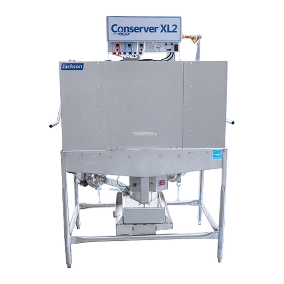
- Page 1 INSTALLATION, OPERATION, INSTALLATION, OPERATION, AND SERVICE MANUAL AND SERVICE MANUAL CONSERVER CONSERVER XL2 DISHMACHINES XL2 DISHMACHINES ® ® Conserver XL2 Manual • 07610-002-10-23-V...
- Page 2 ONE YEAR LIMITED PARTS AND LABOR WARRANTY For a period of one (1) year from date of original installation of a new Jackson Dishmachine (but in no event to exceed eighteen (18) months from date of shipment from Jackson’s factory), Jackson WWS, Inc. (Jackson) will repair or replace, at its discretion, any original part that proves defective in materials or workmanship at the time the Dishmachine was purchased;...
- Page 3 MANUFACTURER'S LIMITED WARRANTY (CONT.) (APPLICABLE ONLY IN THE UNITED STATES AND CANADA) PRODUCT CHANGES: Jackson reserves the right to make changes in design and specification of any component of the Dishmachine as engineering or necessity requires. DISCLAIMER OF WARRANTIES: THERE ARE NO WARRANTIES, EXPRESSED OR IMPLIED, INCLUDING, WITHOUT LIMITATION, ANY IMPLIED WARRANTY OF FITNESS FOR A PARTICULAR PURPOSE OR MERCHANTABILITY, THAT ARE NOT SET FORTH HEREIN, OR THAT EXTEND BEYOND THE DURATION HEREOF.
- Page 4 REVISION HISTORY Made Revision Date Process Details 5-7-04 7040 Added new logo. Changed to new layout. Added new parts for the redesigned Conserver XL unit. 11-8-06 Added instructions and schematics for use with universal timers. 7107, 7257, 7478, 7293, Converted to centered layout with bottom date stamp for revisions. Combined installation and 11-28-07 7553, 7122, technical manuals.
- Page 5 NOMENCLATURE Conserver XL2 Series ® Conserver XL2 Low-temperature, chemical-sanitizing, dual-rack dishmachine. Conserver XL2-CML Low-temperature, chemical-sanitizing, dual-rack dishmachine with left-hand feed-through. Conserver XL2-CMR Low-temperature, chemical-sanitizing, dual-rack dishmachine with right-hand feed-through. The manufacturer provides technical support for all of the dishmachines detailed in this manual.
-
Page 6: Table Of Contents
TABLE OF CONTENTS GUIDES Symbols ............................1 Abbreviations & Acronyms ......................1 SPECIFICATIONS XL2 Dimensions..........................2 XL2-CML Dimensions .........................3 XL2-CMR Dimensions ........................4 Table Dimensions ........................5 Operating Capacities ........................6 Electrical Requirements ......................7 INSTALLATION Installation Instructions ....................... 8 Inspection......................... 8 Unpacking ........................8 Leveling..........................8 Plumbing .......................... - Page 7 TABLE OF CONTENTS MAINTENANCE Preventative Maintenance ......................22 TROUBLESHOOTING Troubleshooting ........................23 PARTS Control Box ..........................27 Chemical Feeder Pump Components..................29 Hood Assembly ......................... 31 Cantilever Arm .......................... 33 Tub Assembly – Left-front ......................35 Tub Assembly – Right-front ...................... 36 Frame Assembly ........................
-
Page 8: Symbols
GUIDES GUIDES SYMBOLS - risk of injury to personnel. WARNING - risk of damage to equipment. CAUTION - risk of electrical shock. - caustic chemicals. - reference data plate. - lockout electrical power. - important note. NOTICE ABBREVIATIONS & ACRONYMS ANSI - American National Standards Institute CFM - Cubic Feet per Minute GHT - Garden Hose Thread... -
Page 9: Specifications
XL2 DIMENSIONS SPECIFICATIONS LEGEND 2 [51 mm] A - Electrical Connection B - Water Inlet (3/4” NPT) C - Drain Connection (2” NPT) D - Chemical Connection 4 [102 mm] 1 1/4 [32 mm] 11 1/4 [286 mm] All dimensions from the floor can be increased 1 1/8”... -
Page 10: Xl2-Cml Dimensions
XL2-CML DIMENSIONS SPECIFICATIONS LEGEND A - Electrical Connection 4 [102 mm] 11 1/2 [295 mm] B - Water Inlet (3/4” NPT) C - Drain Connection (2” NPT) D - Chemical Connection All dimensions from the floor can be increased 1 1/4 [32 mm] 13 1/4 [337 mm] 1 1/8”... -
Page 11: Xl2-Cmr Dimensions
XL2-CMR DIMENSIONS SPECIFICATIONS LEGEND 4 [102 mm] 11 1/2 [295 mm] A - Electrical Connection B - Water Inlet (3/4” NPT) C - Drain Connection (2” NPT) D - Chemical Connection 1 1/4 [32 mm] 13 1/4 [337 mm] All dimensions from the floor can be increased 4 [102 mm] 1 1/8”... - Page 12 TABLE DIMENSIONS SPECIFICATIONS CORNER INSTALLATION (CML/CMR ONLY) XL2-CML 4 [102 mm] ALIGN WITH TABLE - DISTANCE CAN VARY 4 [102 mm] ALIGN WITH TABLE - DISTANCE CAN VARY 20 1/2 [521 mm] OPENING XL2-CMR 4 [102 mm] ALIGN WITH TABLE - DISTANCE CAN VARY 30 [762 mm] 4 [102 mm]...
-
Page 13: Operating Capacities
OPERATING CAPACITIES SPECIFICATIONS Model Designation: Operating Capacity: Racks per Hour without Load Time Racks per Hour with Load Time Dishes per Hour without Load Time 2050 Dishes per Hour with Load Time 1950 Glasses per Hour without Load Time 2952 Glasses per Hour with Load Time 2808 Tank Capacity:... -
Page 14: Electrical Requirements
ELECTRICAL REQUIREMENTS SPECIFICATIONS NOTICE All electrical ratings provided in this manual are for reference only. Always refer to the machine data plate to get exact electrical information for this machine. All electrical work performed on machines should be done in accordance with applicable local, state, territorial, and national codes. -
Page 15: Installation
INSTRUCTIONS INSTALLATION INSPECTION Before installing the , check the packaging and machine for damage. If the machine packaging is damaged, the machine might also be damaged. If there is damage to both the packaging and machine, do not throw away the packaging. The has been machine inspected and packed at the factory and is expected to arrive to you in new, undamaged... -
Page 16: Water Supply Connections
INSTRUCTIONS INSTALLATION WATER SUPPLY If water hardness tests higher than 3 GPG, install the Scaltrol Water Treatment system (see the Plumbing Options page) into the water line before the machine’s incoming CONNECTIONS: water connection point. A water shut-off valve should be installed to allow access for WATER HARDNESS service. -
Page 17: Electrical Power Connections
INSTRUCTIONS INSTALLATION ELECTRICAL POWER Electrical and grounding conductors must comply with the applicable portions of the National Electric Code ANSI/NFPA 70 (latest edition) and/or other electrical codes. CONNECTIONS Refer to the machine data plate for machine operating requirements, machine voltage, total amperage, and serial number. -
Page 18: Priming Chemical Pumps
INSTRUCTIONS INSTALLATION PRIMING CHEMICAL Chemical feeder pumps need priming when the machine is first installed or if the chemical lines have been removed and air was allowed to enter. FEEDER PUMPS CAUTION! Water must be in the sump and wash tank before chemicals are dispensed. CAUTION 1. -
Page 19: Cycle Timer Instructions
Step Start Time Step Duration POWERING ON The display will read "JACKSON WWS" and the firmware version when powered on. This is the Default/Home screen. • If inactive for 15 seconds the blue backlight will turn off. - Page 20 RINSE CYCLE PUMP DRAIN FILL SANI DETER SPARE "M" = Modifed Timing inactive for 10 seconds "F" = Factory Defaults DISH JACKSON WWS CYCLE CYCLE or any other button is COUNT SW v30013M TIMER pressed. STEP STEP START TIME DURATION...
- Page 21 CYCLE PUMP DRAIN FILL SANI DETER SPARE "M" = Modifed Timing changes, so number will "F" = Factory Defaults DISH JACKSON WWS be different depending on CYCLE CYCLE COUNT SW v30013F TIMER when timer was installed. STEP STEP START TIME...
- Page 22 CYCLE TIMER INSTRUCTIONS INSTALLATION PLANT TEST MODE 1. Press and hold CYCLE COUNT button and DOWN ARROW button (under STEP START TIME) simultaneously for 3–4 seconds. SELECT CYCLE STEP TO ADJUST PRESS SAVE TO EXIT RINSE CYCLE PUMP DRAIN FILL SANI DETER SPARE...
-
Page 23: Operation
OPERATING INSTRUCTIONS OPERATION PREPARATION Before operating machine, verify: 1. Sump strainer and pan strainer are in place and clean. 2. Drain stopper is installed. 3. Wash/rinse arms are installed, secure, and rotate freely. POWER UP To place the machine in standby, flip "OFF/ON/FILL" switch to "ON" position. 07610-002-10-23-V... -
Page 24: Filling The Wash Tub
OPERATING INSTRUCTIONS OPERATION FILLING THE 1. For initial fill, close door and depress and hold "OFF/ON/FILL" switch in FILL position for approximately 8–10 seconds. WASH TUB 2. Open door and verify water level is correct. Water must be between two lines on drain stopper. -
Page 25: First Rack
OPERATING INSTRUCTIONS OPERATION FIRST RACK The first rack of ware can quickly reduce the temperature of the wash tank. The first rack will sometimes need to be run again. Any time the hasn't been machine operated for an extended period of time this is possible, but unlikely, and depends on the type of ware, its temperature, and the ambient temperature of the kitchen area. -
Page 26: Shutdown And Cleaning
OPERATING INSTRUCTIONS OPERATION SHUTDOWN 1. Turn machine off by flipping “OFF/ON/FILL” switch to “OFF” position. & CLEANING 2. Open door. 3. Remove drain stopper and allow tub to drain (WARNING! Wash tank water will be hot). WARNING 4. Remove sump strainer and pan strainer. 5. - Page 27 OPERATING INSTRUCTIONS OPERATION SHUTDOWN 8. Verify nozzles and arms are free from obstruction. If clogged, remove end-caps, clean nozzles with a brush, and flush with fresh water. & CLEANING 9. Replace end-caps and ensure they"ve been tightened. 10. Spray or wipe out interior of machine. 11.
-
Page 28: Deliming
OPERATING INSTRUCTIONS OPERATION DELIMING 1. Flip “OFF/ON/FILL” switch to “ON” position. 2. Close door and hold “OFF/ON/FILL” switch in “FILL “ position for approximately 8-10 seconds. 3. Water must be between two lines on drain stopper. 4. Add deliming solution per chemical supplier’s instructions. 5. -
Page 29: Preventative Maintenance
PREVENTATIVE MAINTENANCE MAINTENANCE PREVENTATIVE The manufacturer highly recommends that any maintenance and repairs not specifically discussed in this manual be performed only by qualified service personnel. MAINTENANCE WARNING! Unqualified personnel performing maintenance on the machine may void the warranty, lead to larger problems, or cause harm to the operator. WARNING Following the operating and cleaning instructions in this manual will result in the most efficient results from the machine. -
Page 30: Troubleshooting
TROUBLESHOOTING TROUBLESHOOTING OBSERVATION POSSIBLE CAUSE REMEDY Dishmachine will not run, 1. Service disconnect switch 1. Turn disconnect on. no voltage at wash relay off or faulty. 2. Reset or replace. terminals L1 and T1. 2. Branch circuit breaker 3. Tighten or replace connections. tripped/fuse blown. - Page 31 TROUBLESHOOTING TROUBLESHOOTING OBSERVATION POSSIBLE CAUSE REMEDY Machine will not fill, other 1. Y-strainer plugged. 1. Clean strainer. functions work. 2. Water valve turned off. 2. Turn on water valve. 3. Faulty solenoid valve 3. Replace diaphragm, clean foreign material out of valve body diaphragm.
- Page 32 TROUBLESHOOTING TROUBLESHOOTING OBSERVATION POSSIBLE CAUSE REMEDY Machine runs with door open. 1. Door switch shorted. 1. With machine off, open doors, and with both wires to door switch unplugged, measure continuity between wires on 2. Faulty wash relay (wash relay switch.
- Page 33 TROUBLESHOOTING TROUBLESHOOTING OBSERVATION POSSIBLE CAUSE REMEDY Prime switch does not acti- 1. Faulty prime switch. 1. With the prime switch in the prime position, check for voltage vate sanitizer pump. between the GREY and WHITE/RED wires to switch. If 120 V, 2.
-
Page 34: Parts
CONTROL BOX PARTS TO DRAIN NOTICE SOLENOID *Machines with serial numbers (SEE SCHEMATIC) before 20F386545 have the old earlier manual. CAM timer. See ITEM DESCRIPTION PART NUMBER Switch, Prime 05930-011-49-54 Light, Red 05945-504-07-18 Light, Green 05954-504-08-18 Switch, Delime 05930-301-21-18 Cycle Counter 05990-111-35-38 Screw, 4-40 x 1/4"... - Page 35 CONTROL BOX PARTS ITEM DESCRIPTION PART NUMBER Terminal Block 05940-500-09-61 Contactor, 115 V, 30 A 05945-109-05-69 Terminal Board 05940-021-94-85 Lug, Ground 05940-200-76-00 Spacer, Terminal Block 05700-011-40-05 Lock Nut, 10-24 SS Hex with Nylon Insert 05310-373-01-00 Locknut, 6-32 Hex with Nylon Insert 05310-373-03-00 Fitting, 1/2", Plastic 05975-011-45-13...
-
Page 36: Chemical Feeder Pump Components
CHEMICAL FEEDER PUMP COMPONENTS PARTS NOTICE For complete Chemical Feeder Pump Assembly part numbers, see the Control Box pages. 07610-002-10-23-V... - Page 37 CHEMICAL FEEDER PUMP COMPONENTS PARTS ITEM DESCRIPTION PART NUMBER Housing, Clear 04320-004-59-41 Motor, 14 RPM Rinse-aid Feeder Pump 04320-111-35-13 Motor, 36 RPM Detergent/Sanitizer Feeder Pump 04320-111-35-14 Screw, 8-32 x 1/2” Phillips Flat Head 05305-011-37-06 Tube, 3/16" x 8” Clear Tygoprene 05700-003-22-89 Roller, Black Dot 04320-111-65-27...
-
Page 38: Hood Assembly
HOOD ASSEMBLY PARTS 07610-002-10-23-V... - Page 39 HOOD ASSEMBLY PARTS ITEM DESCRIPTION PART NUMBER Door Guide, Left Rear 05700-021-84-71 Lock Nut, 1/4-20 with Nylon Insert 05310-374-01-00 Bracket, Cantilever Support 09515-003-15-64 Door Assembly, Right Side 05700-004-14-11 Door Guide, Right Rear 05700-021-84-70 Door Guide 05700-021-44-94 Bolt, Hex Head 1/4-20 x 3/4" 05305-274-04-00 Washer, 1/4”...
-
Page 40: Cantilever Arm
CANTILEVER ARM PARTS 24, 18 10, 11, 12 15, 16 23, 18 17, 18 19, 11, 12 07610-002-10-23-V... - Page 41 CANTILEVER ARM PARTS ITEM DESCRIPTION PART NUMBER Complete Cantilever Arm Assembly 05700-002-60-64 Cantilever Arm 05700-002-60-65 Rod, Spring Universal 05700-003-67-39 Yoke Assembly 05700-000-75-77 Cotter Pin 05315-207-01-00 Yoke 05700-000-75-78 Clevis Pin 05315-700-01-00 Nylon Washer 05311-369-03-00 Bushing 03120-100-03-00 Screw, Cap 1/4-20 x 1 5/8" 05305-004-23-57 Washer, 1/4”...
-
Page 42: Tub Assembly - Left-Front
TUB ASSEMBLY – LEFT-FRONT PARTS ITEM DESCRIPTION PART NUMBER Hose Clamp, Regular, 1 5/16" x 2 1/4" 04730-719-18-00 Pump Inlet Nipple 05700-021-33-50 Hose, 1 1/2" ID x 7 3/4" 05700-111-33-52 Hose Clamp, Mini, 7/16" x 25/32" 04730-011-36-05 Wash Motor See Wash Motors Hose Barb Fitting, 3/8"... -
Page 43: Tub Assembly - Right-Front
TUB ASSEMBLY – RIGHT-FRONT PARTS ITEM DESCRIPTION PART NUMBER Plug 04730-011-60-21 Hose Clamp, Regular, 1 5/16" x 2 1/4" 04730-719-18-00 Pump Inlet Nipple 05700-021-33-50 Hose, 1 1/2" ID x 7 3/4" 05700-111-33-52 Hose Clamp, Mini, 7/16" x 25/32" 04730-011-36-05 Wash Motor See Wash Motors Hose Barb Fitting, 3/8"... -
Page 44: Frame Assembly
FRAME ASSEMBLY PARTS ITEM DESCRIPTION PART NUMBER Accumulator 05700-031-66-24 Accumlator Strainer 05700-021-47-17 Accumulator Stop Clip 05700-011-49-11 Adjustable Bullet Foot 05340-108-01-03 07610-002-10-23-V... -
Page 45: Wash Motors
WASH MOTORS PARTS 60 Hz ITEM DESCRIPTION PART NUMBER Motor, 1 HP/115-230 V/60 Hz 06105-004-24-80 50 Hz ITEM DESCRIPTION PART NUMBER Motor, 1 HP/230 V/50 Hz 06105-002-19-87 Liquidtite Connector, 90-degree 05975-111-01-00 Pump Support Assembly 05700-002-05-88 Clamp, 5 5/8"– 6" 04730-011-34-90 07610-002-10-23-V... -
Page 46: Inlet Plumbing Assembly
INLET PLUMBING ASSEMBLY PARTS Complete Inlet Plumbing Assembly, 3/4” 05700-004-49-05 ITEM DESCRIPTION PART NUMBER Y-Strainer 04730-717-02-06 Nipple, Brass, 3/4” x 4 1/2” 04730-004-04-53 Solenoid Valve, 3/4” 04810-100-03-18 Nipple, Brass, 3/4” x 1 3/8” 04730-207-34-00 Y-Strainer 04730-717-02-06 Elbow, Brass, 3/4” 90-degree 04730-206-13-00 Coupling, Water Inlet 05700-004-41-15... -
Page 47: Solenoid Valve Repair Kit
SOLENOID VALVE REPAIR KIT PARTS Screw Data Plate Coil & Housing Valve Bonnet Spring 06401-003-07-40 Spring & Plunger 05700-003-07-40 Plunger 06401-003-07-40 O-Ring Diaphragm 06401-003-07-42 Retainer O-ring & Diaphragm 05700-003-07-42 Diaphragm 06401-003-07-42 Screen Retainer Mesh Screen Valve Body TO TAKE THE SOLENOID VALVE APART Complete 110 Volt Solenoid Valve Assembly 04810-100-53-00 DISASSEMBLY - These valves may be taken apart by... -
Page 48: Plumbing Options
PLUMBING OPTIONS PARTS SHOCK ABSORBER (WATER ARRESTOR) OPTION ITEM DESCRIPTION PART NUMBER Complete Water Arrestor Assembly, 3/4" 05700-002-61-29 Nipple, 3/4” NPT, Close, Brass 04730-207-34-00 Water Arrestor 06685-100-05-00 Tee, 3/4” x 3/4” x 1/2” 04730-211-06-00 WATER TREATMENT OPTION Replacement Cartridge Scaltrol System (inspect at least every 6 months) 04730-003-05-76 RSC-100... -
Page 49: Wash Manifold Assembly
WASH MANIFOLD ASSEMBLY PARTS 07610-002-10-23-V... - Page 50 WASH MANIFOLD ASSEMBLY PARTS ITEM DESCRIPTION PART NUMBER Wash Arm 05700-002-57-98 End-cap (included with arm but can order separately) 05700-011-35-92 Hex Nut 3/8” 05310-276-01-00 Lockwasher 05311-276-01-00 Upper Manifold 05700-031-34-82 Hex Head Bolt 3/8-16 x 7/8” 05306-011-36-95 O-Ring 05330-111-35-15 Manifold 05700-031-34-59 Hex Head Bolt 3/8”...
-
Page 51: Miscellaneous Parts
MISCELLANEOUS PARTS PARTS Parts are not shown to scale in relation to each other. ITEM DESCRIPTION PART NUMBER Intake Sump Strainer 05700-031-45-26 Injection Tube 05700-002-21-52 Injection Tube Gasket 05700-011-45-36 Injection Tube Bushing 05975-002-47-54 Rack Guide 05700-031-45-92 Air-gap Insert, 3/4” 05700-004-34-43 Air-gap, 3/4”... -
Page 52: Xl2/Cml/Cmr 115 V, 60 Hz, Single-Phase
XL2/CML/CMR 115 V, 60 HZ, 1-PHASE SCHEMATICS 07610-002-10-23-V... -
Page 53: Xl2/Cml/Cmr 208/230 V, 50/60 Hz, Single-Phase
XL2/CML/CMR 208/230 V, 50/60 HZ, 1-PHASE SCHEMATICS 07610-002-10-23-V... - Page 54 Jackson WWS, Inc. • 6209 N. US Hwy 25E • Gray, KY 40734 USA 1.888.800.5672 • www.jacksonwws.com Conserver XL2 Manual • 07610-002-10-23-V...
Need help?
Do you have a question about the CONSERVER XL2C and is the answer not in the manual?
Questions and answers