Table of Contents
Advertisement
CHEMICAL SANITIZING, SINGLE AND DUAL RACK
UPRIGHT DOOR DISHMACHINES
INSTALLATION/OPERATION &
TECHNICAL MANUAL
FOR JACKSON MODELS:
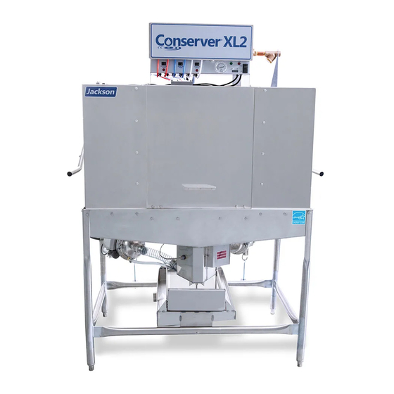
CONSERVER XL, CONSERVER XL2
CONSERVER XL2-CML, CONSERVER XL2-CMR
CONSERVER AXL, CONSERVER AXL2
CONSERVER AXL2-CML, CONSERVER AXL2-CMR
Jackson MSC, LLC.
P.O. BOX 1060
HWY. 25E
BARBOURVILLE, KY. 40906
FAX (606) 523-9196
November 28, 2007
PHONE (606) 523-9795
P/N 7610-002-10-23 (Revision H)
www.jacksonmsc.com
Advertisement
Table of Contents

Related Manuals for Jackson Conserver AXL


Summary of Contents for Jackson Conserver AXL
- Page 1 UPRIGHT DOOR DISHMACHINES INSTALLATION/OPERATION & TECHNICAL MANUAL FOR JACKSON MODELS: CONSERVER XL, CONSERVER XL2 CONSERVER XL2-CML, CONSERVER XL2-CMR CONSERVER AXL, CONSERVER AXL2 CONSERVER AXL2-CML, CONSERVER AXL2-CMR Jackson MSC, LLC. P.O. BOX 1060 HWY. 25E BARBOURVILLE, KY. 40906 FAX (606) 523-9196...
-
Page 2: Manufacturers Warranty
The warranty registration card supplied with the machine must be returned to Jackson MSC within 30 days to validate the warranty. REPLACEMENT PARTS WARRANTY Jackson replacement parts are warranted for a period of 90 days from the date of installation or 180 days from the date of shipment from the factory, which ever occurs first. - Page 3 STOP! PARE! ARRET! CALL 1-888-800-5672 TO REGISTER THIS PRODUCT! FAILURE TO DO SO WILL VOID THE WARRANTY! LLAME AL 1-888-800-5672 PARA REGISTRAR ESTE PRODUCTO! AL NO HACERLO LA GARANTIA SERA ANULADA! S.V.P . APPELER 1-888-800-5672 POUR ENREGISTRER CE PRODUIT, LA GARANTIE SERA ANNULEE POUR TOUT PRODUIT NON- ENREGISTREE...
- Page 4 REVISION MADE REVISION DATE 05-07-04 11-08-06 11-28-07 APPLICABLE 7040 Added 2nd Enodis Logo. Changed to new layout. Added new parts for the redesigned Conserver XL unit. Added instructions and schematics for use with universal timers. 7107, 7257, Converted to centered layout with bottom date stamp for revi- 7478, 7293, sions.
- Page 5 Conserver XL2-CML = Low temperature, chemical sanitizing, dual rack dishmachine with left hand feed Conserver XL2-CMR = Low temperature, chemical sanitizing, dual rack dishmachine with right hand feed Conserver AXL = Low temperature, chemical sanitizing, universal timer, single rack dishmachine Conserver AXL2 = Low temperature, chemical sanitizing, universal timer, dual rack dishmachine...
-
Page 6: Table Of Contents
DESCRIPTION GENERAL Specifications for the Conserver XL Specifications for the Conserver XL2 Series Dimensions Conserver AXL (Universal Timer) Dimensions Conserver AXL2 (Universal Timer) Dimensions Conserver AXL2-CML (Universal Timer) Dimensions Conserver AXL2-CMR (Universal Timer) Dimensions Conserver XL (Starting with S/N 04D10286) -
Page 7: Electrical Diagrams
ELECTRICAL DIAGRAMS Conserver AXL (115 Volt, 60 Hz, Single Phase) Conserver AXL2 (115 Volt, 60 Hz, Single Phase) Conserver AXL2 CML/CMR (115 Volt, 60 Hz, Single Phase) Conserver AXL2 CML/CMR (208-230 Volt, 60 Hz, Single Phase) Conserver AXLS (115 Volt, 60 Hz, Single Phase) -
Page 8: Section 1: Specification Information
SECTION 1: SPECIFICATION INFORMATION... -
Page 9: Specifications For The Conserver Xl
SECTION 1: SPECIFICATION INFORMATION PERFORMANCE/CAPABILITIES OPERATING CAPACITY (RACKS/HOUR) RACKS PER HOUR DISHES PER HOUR GLASSES PER HOUR OPERATING CYCLE (SECONDS) WASH TIME RINSE TIME DWELL TIME TOTAL CYCLE TIME TANK CAPACITY (MINIMUM) WASH TANK (GALLONS) WASH TANK (LITERS) WASH PUMP CAPACITY GALLONS PER MINUTE LITERS PER MINUTE TEMPERATURES... -
Page 10: Specifications For The Conserver Xl2 Series
SECTION 1: SPECIFICATION INFORMATION PERFORMANCE/CAPABILITIES OPERATING CAPACITY (RACKS/HOUR) RACKS PER HOUR RACKS PER HOUR (OPTION) DISHES PER HOUR GLASSES PER HOUR OPERATING CYCLE (SECONDS) WASH TIME RINSE TIME DWELL TIME TOTAL CYCLE TIME TOTAL CYCLE TIME (OPTION) TANK CAPACITY (MINIMUM) WASH TANK (GALLONS) WASH TANK (LITERS) WASH PUMP CAPACITY... -
Page 11: Dimensions Conserver Axl (Universal Timer)
6 3 4 [174mm] 17 1 4 [438mm] Maximum Dish Clearance 68 1/2 [1740mm] 34 [864mm] Table height DIMENSIONS CONSERVER AXL Standard clearance between the wall and the machine with dishtable is 4". 32 [813mm] 6 [155mm] 57 1/4 [1454 mm] Conserver XL Series Installation &... -
Page 12: Dimensions Conserver Axl2 (Universal Timer)
SECTION 1: SPECIFICATION INFORMATION 11 1 4 [286mm] 44 [1117mm] LEGEND: A - Electrical connection B - Water inlet 1/2" I.P.S C - Drain connection 2" I.P.S All vertical dimensions are +/- 1/2" from floor due to adjustable bullet feet. 6 3 4 [171mm] 17 1 4 [438mm] MAXIMUM DISH... -
Page 13: Dimensions Conserver Axl2-Cml (Universal Timer)
SECTION 1: SPECIFICATION INFORMATION DIMENSIONS CONSERVER AXL2-CML LEGEND: A - Electrical connection B - Water inlet 1/2" I.P.S 78 [1981mm] C - Drain connection 2" I.P.S 65 1 4 [1658mm] All vertical dimensions are +/- 1/2" from floor due to adjustable bullet feet. 11 1 2 [295mm] 4 [102mm] 13 1 4 [337mm]... -
Page 14: Dimensions Conserver Axl2-Cmr (Universal Timer)
SECTION 1: SPECIFICATION INFORMATION LEGEND: A - Electrical connection B - Water inlet 1/2" I.P.S C - Drain connection 2" I.P.S All vertical dimensions are +/- 1/2" from floor due to adjustable bullet feet. 13 1 4 [337mm] [635mm] 44 [1118mm] 6 3/4 [171mm] 17 1 4 [438mm] MAXIMUM DISH CLEARANCE... -
Page 15: Dimensions Conserver Xl (Starting With S/N 04D10286)
SECTION 1: SPECIFICATION INFORMATION DIMENSIONS CONSERVER XL (Starting with S/N 04D10286) LEGEND A - ELECTRICAL CONNECTION B - WATER INLET, 3/4" IPS C - DRAIN CONNECTION, 2" IPS D - STANDARD CLEARANCE BETWEEN MACHINE AND WALL (WITH DISHTABLE) IS 4" [105mm] ALL DIMENSIONS ARE +/- 1/2"... -
Page 16: Dimensions Conserver Xl2
SECTION 1: SPECIFICATION INFORMATION DIMENSIONS CONSERVER XL2 Conserver XL Series Technical Manual 7610-002-10-23 Issued: 11-28-2007 Revised: N/A... -
Page 17: Dimensions Conserver Xl2-Cml
SECTION 1: SPECIFICATION INFORMATION 1mm] 4 [101mm] 20 3 4 [526mm] 44 [1115mm] 46 1 4 [1176mm] 66 [1679mm] 17 1 2 [445mm] 56 1 2 [1438mm] 34 [863mm] 10 1 4 [261mm] 13 1 2 [344mm] DIMENSIONS CONSERVER XL2-CML 11 3 4 [296mm] 32 [814mm] 26 [662mm]... -
Page 18: Dimensions Conserver Xl2-Cmr
SECTION 1: SPECIFICATION INFORMATION 32 [814mm] LEGEND 26 [662mm] A - ELECTRICAL CONNECTION B - WATER INLET, 3/4" IPS C - DRAIN CONNECTION, 2" IPS ALL DIMENSIONS ARE +/- 1/2" FROM FLOOR DUE TO ADJUSTABLE BULLET FEET. 4 1 2 [112mm] 1 [24mm] 60 1 2 [1536mm] 75 3 4 [1925mm]... -
Page 19: Xls Bowl Option
SECTION 1: SPECIFICATION INFORMATION XLS BOWL OPTION Legend A - Electrical Connection B - Water Connection, 21 1 2 [545mm] 18 [459mm] Bowl Option - Front Side View 5 [128mm] Bowl Option - Right Side View Conserver XL Series Technical Manual 7610-002-10-23 Issued: 11-28-2007 Revised: N/A "... -
Page 20: Table Dimensions
SECTION 1: SPECIFICATION INFORMATION 20 1/2” (521mm) 2 1/2” (63mm) OPENING 25 1/4” 4” (102mm) (641mm) MINIMUM 3/4” (19mm) 20 1/2” (521mm) 4” (102mm) MINIMUM TABLE DIMENSIONS STRAIGHT THROUGH INSTALLATION TABLE DIMENSIONS 25 1/4” (641mm) XL SERIES Conserver XL Series Technical Manual 7610-002-10-23 Issued: 11-28-2007 Revised: N/A 4”... -
Page 21: Section 2: Installation/Operation Instructions
SECTION 2: INSTALLATION/OPERATION INSTRUCTIONS... - Page 22 UNPACKING THE DISHMACHINE: Once the machine has been removed from the container, ensure that there are no miss- ing parts from the machine. This may not be obvious at first. If it is discovered that an item is missing, contact Jackson imme- diately to have the missing item shipped to you.
-
Page 23: Electrical Installation Instructions
SECTION 2: INSTALLATION/OPERATION INSTRUCTIONS ELECTRICAL POWER CONNECTION: Electrical and grounding connections must comply with the applicable portions of the National Electrical Code ANSI/NFPA 70 (latest edition) and/or other electrical codes. Disconnect electrical power supply and place a tag at the disconnect switch to indicate that you are working on the circuit. The dishmachine data plate is located on the right side and to the front of the machine. -
Page 24: Chemical Dispensing Equipment
SECTION 2: INSTALLATION/OPERATION INSTRUCTIONS TO PREPARE PUMPS FOR OPERATION The Conserver XL dishmachine is supplied with detergent, rinse additive and sanitizer dispensing chemical feeder pumps. Locate the open ends of the chemical tubes with the tube stiffeners and place each one in the appropriate container. A. -
Page 25: Operation Instructions
SECTION 2: INSTALLATION/OPERATION INSTRUCTIONS OPERATION INSTRUCTIONS PREPARATION: Before proceeding with the start-up of the unit, verify the following: 1. The sump strainer is in place and is clean. 2. The drain stopper is installed. 3. That the wash and rinse arms are screwed securely into place and that their endcaps are tight. The wash and rinse arms should rotate freely. - Page 26 SECTION 2: INSTALLATION/OPERATION INSTRUCTIONS OPERATION INSTRUCTIONS (CONTINUED) WASHING A RACK OF WARE: To wash a rack, open the doors completely (being careful for hot water that may drip from the doors) and slide the rack into the unit. Close the doors and the unit will start automatically.
-
Page 27: Mechanical Cam Timer Operation
SECTION 2: INSTALLATION/OPERATION INSTRUCTIONS CAM TIMER OPERATION The Conserver XL Series cam timer is a 1 minute, 30 second, 8-cam timer (cam 8 is a spare) that controls the operation of the dishmachine. The following is a description of the set points for each cam and the function of each switch. CAM 1: Cam 1 is a cut cam with a single notch and serves as the cycle/reset control. - Page 28 SECTION 2: INSTALLATION/OPERATION INSTRUCTIONS CAM TIMER OPERATION (CONTINUED) CAM 6: Cam 6 is an adjustable can and controls the detergent pump. FUNCTION: The detergent pump cam works off the normally closed contacts of cam 6. This requires the switch arm to be held open by the cam and allowed to drop into the notch to operate the pump.
-
Page 29: Mechanical Timing Sequence Conserver Xl
SECTION 2: INSTALLATION/OPERATION INSTRUCTIONS MECHANICAL TIMER TIMING SEQUENCE 2 SECONDS INTO CYCLE *Wash pump starts, runs for 40 seconds, then shuts down. Controlled by C2 cam. 4 SECONDS INTO CYCLE *Detergent feed pump is energized. The length of time will be field determined. Time will depend on the detergent used and water conditions. -
Page 30: Universal Timer Programming Instructions
SECTION 2: INSTALLATION/OPERATION INSTRUCTIONS UNIVERSAL TIMER PROGRAMMING INSTRUCTIONS INSTRUCTIONS FOR CHEMICAL FEEDER PUMPS (FOR INSTALLATION TECHNICIAN ONLY) To access the programming mode, the machine must be ON, and idle (between cycles). On the timer board, press both the MOVE and ENTER buttons on the timer board simultaneously. The PROGRAM light will illuminate and the A light will blink. -
Page 31: Rinse Aid
SECTION 2: INSTALLATION/OPERATION INSTRUCTIONS UNIVERSAL TIMER PROGRAMMING INSTRUCTIONS (CONTINUED) Please note that options A, B and D are not adjustable outputs. Timer Programming Board DRAIN FILL SANITIZER DETERGENT RINSE AID ACCEPT MOVE ENTER Conserver XL Series Technical Manual 7610-002-10-23 Issued: 11-28-2007 Revised: N/A Time in seconds. -
Page 32: Section 3: Preventative Maintenance
SECTION 3: PREVENTATIVE MAINTENANCE... - Page 33 The dishmachines covered in this manual are designed to operate with a minimum of interaction with the operator. However, this does not mean that some items will not wear out in time. Jackson highly recommends that any maintenance and repairs not specifically discussed in this manual should be performed by QUALIFIED SERVICE PERSONNEL ONLY.
-
Page 34: Section 4: Troubleshooting Section
SECTION 4: TROUBLESHOOTING SECTION... - Page 35 WARNING: Inspection, testing and repair of electrical equipment should be performed only by qualified service per- sonnel. Certain procedures in this section require electrical tests or measurements while power is applied to the machine. Exercise extreme caution at all times. If test points are not easily accessible, disconnect power, attach test equipment and reapply power to test.
- Page 36 SECTION 4: TROUBLESHOOTING COMMON PROBLEMS (DOMESTIC UNITS) Problem: Machine will not fill, other functions work. 1. Y-strainer plugged. Clean strainer. 2. Water valve(s) turned off. Turn on water valves. 3. Faulty solenoid valve diaphragm. Replace diaphragm, clean foreign material out of valve body and orifices. 4.
- Page 37 SECTION 4: TROUBLESHOOTING COMMON PROBLEMS (DOMESTIC UNITS) Problem: Machine runs with door open. 1. Door switch shorted. With machine off, open doors, and with both wires to door switch unplugged, measure continuity between wires on switch. If there is continuity, replace the switch. 2.
- Page 38 SECTION 4: TROUBLESHOOTING COMMON PROBLEMS (DOMESTIC UNITS) Problem: Prime switch does not activate sanitizer pump. 1. Faulty prime switch. With the prime switch in the prime position, check for voltage between the GREY and WHITE/RED wires to switch. If 120V, replace the switch. 2.
- Page 39 WARNING: Inspection, testing and repair of electrical equipment should be performed only by qualified service per- sonnel. Certain procedures in this section require electrical tests or measurements while power is applied to the machine. Exercise extreme caution at all times. If test points are not easily accessible, disconnect power, attach test equipment and reapply power to test.
- Page 40 SECTION 4: TROUBLESHOOTING COMMON PROBLEMS (EXPORT UNITS) Problem: Machine will not fill, other functions work. 1. Y-strainer plugged. Clean strainer. 2. Water valve(s) turned off. Turn on water valves. 3. Faulty solenoid valve diaphragm. Replace diaphragm, clean foreign material out of valve body and orifices. 4.
- Page 41 SECTION 4: TROUBLESHOOTING COMMON PROBLEMS (EXPORT UNITS) Problem: Machine runs with door open. 1. Door switch shorted. With machine off, open doors, and with both wires to door switch unplugged, measure continuity between wires on switch. If there is continuity, replace the switch. 2.
- Page 42 SECTION 4: TROUBLESHOOTING COMMON PROBLEMS (EXPORT UNITS) Problem: Prime switch does not activate sanitizer pump. 1. Faulty prime switch. With the prime switch in the prime position, check for voltage between the GREY and WHITE/RED wires to switch. If 220V, replace the switch. 2.
-
Page 43: Section 5: Parts Section
SECTION 5: PARTS SECTION... -
Page 44: Control Box Assembly (Universal Timer)
CONTROL BOX ASSEMBLIES - UNIVERSAL TIMER 33, 34 SECTION 5: PARTS SECTION Conserver XL Series Technical Manual 7610-002-10-23 Issued: 11-28-2007 Revised: N/A 18, 19 18, 19 16, 17 11, 12... - Page 45 CONTROL BOX ASSEMBLIES - UNIVERSAL TIMER (CONTINUED) ITEM DESCRIPTION Control Box Assembly Decal, Warning-Disconnect Power Decal, Control Box Upper Decal, Control Box Lower Switch, Prime Thermometer Decal, Wash/Rinse 120F Switch, DPD Fitting, Brass Nut, Lock Switch, Reed Grommet Switch, On/Off, DPST Cycle Counter, 115 Volt Cycle Counter, 240 Volt Screw, 4-40 x 1/4"...
-
Page 46: Control Box Assembly (Mechanicla Timer)
CONTROL BOX ASSEMBLIES - MECHANICAL TIMER Conserver XL Control Box Assembly ITEM DESCRIPTION Control Box Weldment, Conserver XL Control Box Weldment, Conserver XL2 Series Cover, Control Box Decal, Warning-Disconnect Power Cotter Pin, 3/32 x 3/4" Decal, Control Box Front, Conserver XL Decal, Control Box Front, Conserver XL2 Series SECTION 5: PARTS SECTION 26, 31... - Page 47 CONTROL BOX ASSEMBLY - WITH MECHANICAL TIMER (CONTINUED) ITEM DESCRIPTION Thermometer Switch, On/Off, DPST Cycle Light Power Light Cycle Counter, 115 Volt Cycle Counter, 240 Volt Chemical Feeder Pump Kit Assembly Chemical Feeder Pump Kit Assembly Stiffener, 17 3/8" Tubing, Blue Tubing, Red Tubing, White Drip Shield...
-
Page 48: Xls Bowl Option
SECTION 5: PARTS SECTION XLS BOWL OPTION Conserver XL Series Technical Manual 7610-002-10-23 Issued: 11-28-2007 Revised: N/A... - Page 49 ITEM DESCRIPTION Thermometer Cycle Light, Green Power Light, Red Cycle Counter, 115 Volt Cycle Counter, 240 Volt Terminal Block Terminal Block Spacer Decal, Power Connections Ground Wire Lug Terminal Board Switch, Delime Contactor, 115 Volt Stand, Control Box Cover, Control Box Lock Kit Decal, Control Box Decal, Sanitizer and Rinse Aid...
-
Page 50: Mechanical 8 Cam Timer
SECTION 5: PARTS SECTION MECHANICAL 8 CAM TIMER Timer Motor CYCLE/ 05945-306-14-00 RESET WASH Conserver XL Series Technical Manual 7610-002-10-23 Issued: 11-28-2007 Revised: N/A RINSE DRAIN DETERGENT FILL SANITIZER Microswitch Qty. 8 05930-01-65-81 SPARE... -
Page 51: Chemical Feeder Pump Assembly
Screw, 8-32 x 1/2” Phillips Flat Head 2 per 05305-011-37-06 Screw, 6-32 x 3/4” Phillips Pan Head 4 per 05305-011-37-05 Front Housing 04320-111-37-08 Roller, Red (Detergent/Sanitizer) 04320-111-36-70 Roller, White (Rinse Aid) 04320-002-82-28 If using Tygroprene Tubing: Roller, White 04320-002-82-28 Roller, Black 04320-111-65-27 SECTION 5: PARTS SECTION CHEMICAL FEEDER PUMP ASSEMBLY... -
Page 52: Hood Assembly (Starting With S/N 04D10286)
Conserver AXL Hood Weldment ITEM DESCRIPTION Hood Weldment, Conserver AXL Hood Weldment, Conserver XL (Starting with S/N 04d10286) Hood Support Block Spacer Washer, 1/4" ID S/S Screw, 1/4"-20 x 1 1/8" Long S/S Locknut, 1/4”-20 S/S Hex with Nylon Insert Screw, 1/4"-20 x 1/2"... - Page 53 OLD STYLE: If your unit uses items 5 and 6, it is the old style hood weldment. Items 3 thru 6 are used only with the old style Hood Weldment. The hood will have the proper mounting holes in the rear door guides and in the hood itself. NEW STYLE: If your unit does not use items 5 and 6, then it is the new style hood weldment.
-
Page 54: Cantilever Arm Assembly, Double Bracket Mount
SECTION 5: PARTS SECTION CANTILEVER ARM (DOUBLE BRACKET MOUNT) 10, 11, 12 24, 18 23, 18 15, 16 17, 18 21, 25 19, 11, 12 25, 26 Conserver XL Series Technical Manual 7610-002-10-23 Issued: 11-28-2007 Revised: N/A... - Page 55 CANTILEVER ARM (DOUBLE BRACKET MOUNT) (CONTINUED) ITEM DESCRIPTION Arm, Cantilever, Conserver XL (Prior to S/N 04D10286) Arm, Cantilever, Conserver XL (Starting with S/N 04D10286) Arm, Cantilever, Conserver AXL Arm, Cantilever, Conserver XL2 Spring Pin, 1/4” Dia. x 1 1/8” Long Yoke Assembly Cotter Pin Yoke Clevis Pin, 5/16”...
-
Page 56: Cantilever Arm Assembly, Conserver Xl2 Single Bracket Mount
CONSERVER XL2 CANTILEVER ARM ASSEMBLY (SINGLE BRACKET MOUNT) U Bracket Assembly ITEM DESCRIPTION Hex Nut, 1/4"-20 with Nylon Insert, S/S Wear Strip UHMW Sleeve Bolt, 1/4"-20 x 1 3/4", S/S Link, Spring to Cantilever Arm Cantilever Spring Cantilever Eye Bolt Washer, Impeller Nut, 3/8"-16 Hex, S/S Cantilever Arm... -
Page 57: Conserver Xl Wash Tub & Frame Assembly (Starting With S/N 04D10286)
CONSERVER XL WASH TUB & FRAME ASSEMBLY (Starting with S/N 04D10286) False Panel Weldment 05700-002-51-66 ITEM DESCRIPTION Tub Weldment, Conserver XL (Prior to S/N 04D10286) Tub Weldment, Conserver XL (Starting with S/N 04D10286) Fitting, Chemical Drip Spillway Weldment Cover, Drain Chute Drain Seat Gasket Sump Strainer Drain Seat Insert... - Page 58 CONSERVER XL2 TUB ASSEMBLY (LEFT FRONT VIEW) ITEM DESCRIPTION Lower Wash Manifold Weldment Casting, Manifold Wedge Manifold Gasket Wash Tub Weldment Wash Motor Support Assembly Bracket, Pump Support Weldment Bracket, Lower Pump Support Nut, 1/4"-20 Serrated Nut Wash Motor 60 Cycle Fitting, Brass Elbow Pump Inlet Nipple Hose Clamp, Regular, 1 5/16"...
- Page 59 CONSERVER XL2 SERIES TUB ASSEMBLY (RIGHT FRONT VIEW) * Represents an item not shown. ITEM DESCRIPTION Locknut, 10-24 S/S Hex with Nylon Insert Drain Solenoid, 115V Drain Solenoid, 240V Drain Solenoid Box Drain Solenoid Box Cover Locknut, 1/4"-20 S/S Hex with Nylon Insert Drain Link Assembly Drain Link Drain Link Connector...
-
Page 60: Frame Weldment & Accumulator, Conserver Xl2 Series
CONSERVER XL2 SERIES FRAME WELDMENT & ACCUMULATOR Frame Weldment, Single Bracket 05700-031-45-16 Frame Weldment, Double Bracket 05700-002-61-22 SECTION 5: PARTS SECTION Bullet Foot 05340-108-01-03 Accumulator Stop Clip 05700-011-49-11 Locknut, 10-24 S/S with Nylon Insert 05310-373-01-00 Conserver XL Series Technical Manual 7610-002-10-23 Issued: 11-28-2007 Revised: N/A Accumulator Strainer 05700-021-47-17... -
Page 61: Incoming Plumbing Assemblies
INCOMING PLUMBING ASSEMBLIES 3/4" NPT x 90° Elbow 04730-406-42-01 3/4”-14 NPS Locknut 04730-208-04-00 Diverter End Cap 05700-021-45-32 Conserver AXL Incoming Plumbing Assembly Elbow, 90 Deg. 1/2” Street 04730-206-08-00 1/2" NPT x 2" Nipple 2 Per 04730-011-38-29 Conserver XL Series Technical Manual 7610-002-10-23 Issued: 11-28-2007 Revised: N/A 3/4"... -
Page 62: Solenoid Valve Repair Kits, 3/4
3/4” SOLENOID VALVE & 3/4” NPT VACUUM BREAKER REPAIR PARTS KITS Data Plate Valve Bonnet Diaphragm Retainer Screen Retainer Valve Body Complete 110 Volt Solenoid Valve Assembly 04810-100-53-00 Coil & Housing only 04810-200-01-18 Complete 240 Volt Solenoid Valve Assembly 04810-100-03-18 Coil &... -
Page 63: Wash Motor Assembly, Conserver Xl
ITEM DESCRIPTION Pump & Motor Assembly, 50 HZ Pump Assembly, 50 HZ Motor Assembly, 50 HZ Pump & Motor Assembly, 60 HZ Pump Assembly, 60 HZ Motor Assembly, 60 HZ Pump Support Assembly Nipple, Pump Outlet Clamp, 1 5/16" to 2 1/4" Fitting, Brass Elbow Clamp, 7/16"... -
Page 64: Motor & Pump Assembly
Complete Pump & Motor Assembly, 60HZ 06105-002-69-78 Pump Only Assembly, 60HZ (Area indicated within box, Casing is included) 05700-002-79-51 Pump Casing (Not shown), 60HZ 05700-002-85-01 Shim Kit, 60HZ 05330-002-41-28 Case Capscrew, 60HZ 05305-002-81-88 Impeller Assembly, 60HZ 05700-002-81-86 Impeller Assembly, 50HZ 05700-002-41-49 SECTION 5: PARTS SECTION MOTOR &... -
Page 65: Wash Arm /Wash Manifold Assembly
Complete Manifold Assembly (1 for Conserver XL and 2 for Conserver XL2 Series) Casting, Upper Wash Manifold 05700-031-34-82 O-Ring 2 per assembly 05330-111-35-15 Manifold Tube (Conserver XL Prior to S/N 04D10286) 05700-002-00-19 Manifold Tube (Conserver XL2 Series) (Conserver XL Starting with S/N 04D10286) 05700-031-34-59 Manifold Positioning Tube Bracket... -
Page 66: Drain Solenoid Assembly
ITEM DESCRIPTION Solenoid Bracket Weldment, Conserver XL (Prior to S/N 04D10286) Solenoid Housing Weldment, Conserver XL (Starting with S/N 04D10286) Elbow, 3/8" Tube x 3/8"-18 NPT Locknut, Brass, 3/8"-18 NPT Locknut, 10-24 S/S Hex with Nylon Insert Cotter Pin, 3/32 x 3/4" Long Drain, Solenoid, 115 V Kit, Drain, Solenoid, 115 V Drain, Solenoid, 240 V... -
Page 67: Miscellaneous Parts
Conserver XL2 Intake Pump Strainer Weldment 05700-031-45-26 Stand Pipe Assembly 05700-031-35-55 Conserver XL Rack Guide Assembly 05700-031-36-76 SECTION 5: PARTS SECTION MISCELLANEOUS PARTS Conserver XL2 Rack Guide Weldment 05700-031-45-92 Conserver XL2 Injection Tube Weldment 05700-002-21-52 Conserver XL2 Injection Tube Gasket 05700-011-45-36 Conserver XL2 Injection Tube Bushing... -
Page 68: Conserver Xl2-Cml Assembly Options
YOKE ASSEMBLY SECTION 5: PARTS SECTION CML ASSEMBLY OPTIONS Conserver XL Series Technical Manual 7610-002-10-23 Issued: 11-28-2007 Revised: N/A 00000000... - Page 69 ITEM DESCRIPTION Front Door Assembly Front Door Door Glides UHMW Inner Door Guide Cantilever Arm Assembly Cantilever Arm Weldment Plug Spring Pin, 1/4" Dia. X 1 1/8" Long Yoke Assembly Hinge, Slotted Front Door Bracket Tub Weldment Hood Weldment Frame Weldment Right Door Assembly Right Door Weldment Door Glides UHMW...
-
Page 70: Conserver Xl2-Cml Assembly Options
YOKE ASSEMBLY SECTION 5: PARTS SECTION CMR ASSEMBLY OPTIONS Conserver XL Series Technical Manual 7610-002-10-23 Issued: 11-28-2007 Revised: N/A... - Page 71 ITEM DESCRIPTION Hood Weldment (Conserver XL2-CMR Shown) Hood Weldment (Conserver AXL2-CMR with Centered Control Box Not Shown) Cantilever Arm Assembly Cantilever Arm Weldment Plug Spring Pin, 1/4” Dia. x 1-1/8” Long Yoke Assembly Tub Weldment Inner Door Guide Front Door Assembly Front Door Door Glide, UHMW Hinge, Slotted...
-
Page 72: Hood Assembly, Conserver Xl (Prior To S/N 04D10286)
CONSERVER XL HOOD ASSEMBLY (Prior to S/N 04D10286) ITEM DESCRIPTION Hood Weldment Support, Left, Hood Support, Right, Hood Right Door Guide Left Door Guide Door Guide Locknut, 1/4"-20 with Nylon Insert, S/S Washer, 1/4"-20 Bolt, 1/4"-20 x 1/2" Long Bolt, 1/4"-20 x 3/4" Long Support Bracket Wear Buttons SECTION 5: PARTS SECTION... -
Page 73: Conserver Xl Door & Wrap Assemblies (Prior To S/N 04D10286)
CONSERVER XL DOOR & WRAP ASSEMBLIES (Prior to S/N 04D10286) Door Wrap 05700-001-99-96 Screw, Phillips Flathead, 1/4"-20 x 1 1/2" Nylon Door Bushing 6 per assembly 05700-000-86-66 Washer, Lock, Split, 1/4", S/S Door Guides 05330-600-02-00 Conserver XL Left Door Assembly with Door Guides 05700-002-04-51 Conserver XL Left Door... -
Page 74: Frame Assembly & False Panel, Conserver Xl (Prior To S/N 04D10286)
CONSERVER XL FRAME ASSEMBLY & LEFT HANDED FALSE PANEL WELDMENT (Prior to S/N 04D10286) ITEM DESCRIPTION Lower Frame, Conserver XL Leg, Front Left Frame Assembly Leg, Short, Conserver XL Bracket, Spring Mounting Tub Support Bullet Feet Bolt, 1/4"-20 x 1/2" Long Washer, Flat, 1/4"... -
Page 75: False Panel Installation
False Panel Weldment 05700-002-51-66 False Panel Kit 05700-003-12-93 Insert this side first. Bottom of side panel. SECTION 5: PARTS SECTION FALSE PANEL INSTALLATION False panel positioned in unit. 1. Loosen the rack assembly from the unit. 2. False panel will mount to the rack; inside the dishmachine. 3. -
Page 76: Section 6: Electrical Schematics
SECTION 6: ELECTRICAL SCHEMATICS... -
Page 77: Conserver Axl (115 Volt, 60 Hz, Single Phase)
SECTION 6: ELECTRICAL SCHEMATICS CONSERVER AXL 115 VOLT - 60 HERTZ - SINGLE PHASE Conserver XL Series Technical Manual 7610-002-10-23 Issued: 11-28-2007 Revised: N/A... -
Page 78: Conserver Axl2 (115 Volt, 60 Hz, Single Phase)
SECTION 6: ELECTRICAL SCHEMATICS CONSERVER AXL2 115 VOLT - 60 HERTZ - SINGLE PHASE Conserver XL Series Technical Manual 7610-002-10-23 Issued: 11-28-2007 Revised: N/A... -
Page 79: Conserver Axl2 Cml/Cmr (115 Volt, 60 Hz, Single Phase)
SECTION 6: ELECTRICAL SCHEMATICS CONSERVER AXL2-CML/CMR 115 VOLT - 60 HERTZ - SINGLE PHASE Conserver XL Series Technical Manual 7610-002-10-23 Issued: 11-28-2007 Revised: N/A... -
Page 80: Conserver Axl2 Cml/Cmr (208-230 Volt, 60 Hz, Single Phase)
SECTION 6: ELECTRICAL SCHEMATICS CONSERVER AXL2-CML/CMR 208-230 VOLT - 60 HERTZ - SINGLE PHASE Conserver XL Series Technical Manual 7610-002-10-23 Issued: 11-28-2007 Revised: N/A... -
Page 81: Conserver Axls (115 Volt, 60 Hz, Single Phase)
SECTION 6: ELECTRICAL SCHEMATICS CONSERVER AXLS 115 VOLT - 60 HERTZ - SINGLE PHASE Conserver XL Series Technical Manual 7610-002-10-23 Issued: 11-28-2007 Revised: N/A... -
Page 82: Conserver Axls2 Cml/Cmr (115 Volt, 60 Hz, Single Phase)
SECTION 6: ELECTRICAL SCHEMATICS CONSERVER AXLS2 115 VOLT - 60 HERTZ - SINGLE PHASE Conserver XL Series Technical Manual 7610-002-10-23 Issued: 11-28-2007 Revised: N/A... -
Page 83: Conserver Xl (115 Volt, 60 Hz, Single Phase)
SECTION 6: ELECTRICAL SCHEMATICS CONSERVER XL (MECHANICAL TIMER) 115 VOLT - 60 HERTZ - SINGLE PHASE Conserver XL Series Technical Manual 7610-002-10-23 Issued: 11-28-2007 Revised: N/A... -
Page 84: Conserver Xl (220 Volt, 50 Hz, Single Phase)
SECTION 6: ELECTRICAL SCHEMATICS CONSERVER XL2 SERIES (MECHANICAL TIMER) 220 VOLT - 50 HERTZ - SINGLE PHASE Conserver XL Series Technical Manual 7610-002-10-23 Issued: 11-28-2007 Revised: N/A... -
Page 85: Conserver Xl2 (115 Volt, 60 Hz, Single Phase)
SECTION 6: ELECTRICAL SCHEMATICS CONSERVER XL2 (MECHANICAL TIMER) 115 VOLT - 60 HERTZ - SINGLE PHASE Conserver XL Series Technical Manual 7610-002-10-23 Issued: 11-28-2007 Revised: N/A... -
Page 86: Conserver Xl2 Cml/Cmr (115 Volt, 60 Hz, Single Phase)
SECTION 6: ELECTRICAL SCHEMATICS CONSERVER XL2-CM (MECHANICAL TIMER) 115 VOLT - 60 HERTZ - SINGLE PHASE Conserver XL Series Technical Manual 7610-002-10-23 Issued: 11-28-2007 Revised: N/A... -
Page 87: Section 7: Jackson Maintenance & Repair Centers
SECTION 7: JACKSON MAINTENANCE & REPAIR CENTERS... -
Page 88: Alabama To Florida
SECTION 7: JACKSON MAINTENANCE & REPAIR CENTERS ALABAMA CALIFORNIA JONES-McLEOD APPLIANCE BARKERS FOOD MACHINERY SERVICES 1616 7TH AVE. NORTH 5367 SECOND STREET BIRMINGHAM, AL 35203 IRWINDALE, CA 91706 (205) 251-0159 (626) 960-9390 800-821-1150 800-258-6999 FAX: (205) 322-1440 FAX: (626) 337-4541 service@jones-mcleod.com... -
Page 89: Florida To Maryland
SECTION 7: JACKSON MAINTENANCE & REPAIR CENTERS JONES-McLEOD APPLIANCE HAWAII 854 LAKESIDE DRIVE FOOD EQMT. PARTS & MOBILE, AL 36693 SERVICE CO. (251) 666-7278 300 PUUHALE RD. 800-237-9859 HONOLULU, HI 96819 FAX: (251) 661-0223 (808) 847-4871 service@jones-mcleod.com FAX: (808) 842-1560 fepsco@hula.net... -
Page 90: Maryland To New York
SECTION 7: JACKSON MAINTENANCE & REPAIR CENTERS EMR SERVICE DIVISION MICHIGAN 106 WILLIAMSPORT CIRCLE SALISBURY, MD 21804 GCS SERVICE INC. (410) 543-8197 LIVONIA, MI 888-687-8080 (248) 426-9500 FAX: (410) 548-4038 800-772-2936 baltparts@emrco.com FAX: (248) 426-7555 EMR SERVICE DIVISION 5316 Sunnyside Ave. -
Page 91: New York To Pennsylvania
SECTION 7: JACKSON MAINTENANCE & REPAIR CENTERS B.E.S.T. INC. AUTHORIZED APPLIANCE 3003 GENESEE STREET SERVICECENTER BUFFALO, NY 14225 904 S. MARSHALL ST. (716) 893-6464 WINSTON-SALEM, NC 27403 800-338-5011 (336) 725-5396 FAX: (716) 893-6466 FAX:(336) 721-1289 bestserv@aol.com AUTHORIZED APPLIANCE DUFFY'S EQUIPMENT SVC. -
Page 92: Rhode Island To Wisconsin
SECTION 7: JACKSON MAINTENANCE & REPAIR CENTERS RHODE ISLAND WHALEY FOODSERVICE REPAIRS GCS SERVICE INC. 4740-A FRANCHISE STREET EAST PROVIDENCE, RI N. CHARLESTON, SC 29418 (401) 434-6803 (843) 760-2110 800-462-6012 FAX: (843) 760-2255 FAX: (401) 438-9400 info@whaleyfoodservice.com SUPERIOR KITCHEN SER- SOUTH DAKOTA VICE INC. -
Page 93: Wisconsin To Wyoming/International
SECTION 7: JACKSON MAINTENANCE & REPAIR CENTERS WISCONSIN TO WYOMING/INTERNATIONAL GENERAL PARTS, INC. W223 N735 SARATOGA DRIVE WAUKESHA, WI 53186 (262) 650-6666 (800) 279-9946 (262) 650-6660 FAX WYOMING HAWKINS COMMERCIAL APPLIANCE SERVICE 3000 S. WYANDOT ST. ENGLEWOOD, CO 80110 (303) 781-5548...
Need help?
Do you have a question about the Conserver AXL and is the answer not in the manual?
Questions and answers