Advertisement
Quick Links
®
Description
The ISL45041EVAL1Z is the evaluation board for the
2
ISL45041 I
C LCD Module Calibrator. All materials of the kit
are RoHS compliant. The evaluation kit comes complete
with: ISL45041EVAL1Z board, USB to I
USB cable to connect the converter board to a PC, Power
2
and I
C cables for the ISL45041EVAL board. The Software
and related documentation for the eval kit are downloadable
from Intersil's website at www.intersil.com.
2
The USB to I
C converter board (USB-I2CIO Rev B2) allows
the user to adjust and program the ISL45041 V
using a PC.
This application note will guide the user through the process
2
of installing the USB to I
C drivers, ISL45041 Graphical User
Interface (GUI) and configuring the ISL45041EVAL1Z board
for evaluation of the ISL45041.
Additional equipment required are two power supplies, one
volt meter and a PC (Windows 98/XP/2000 machine with a
standard USB port). The board is designed to operate from an
AVDD supply (5V to 18V), and VDD supply (2.5V to 3.6V).
Installing the ISL4504x Software
1. Log on to www.intersil.com/cda/home.
2. In the upper right corner of the webpage, type in
ISL45041 in the white box and click search. This will bring
you to the product information page. Click on the data
sheet link Datasheets, Related Docs & Simulations. Now
Application Note
2
C converter board,
voltage
COM
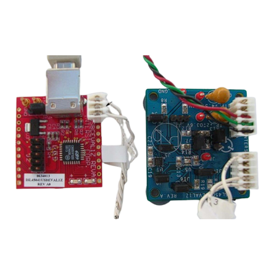
2
FIGURE 1. USB-I
CIO BOARD (MADE BY INTERSIL)
1
CAUTION: These devices are sensitive to electrostatic discharge; follow proper IC Handling Procedures.
1-888-INTERSIL or 1-888-468-3774
ISL45041EVAL1Z User's Manual
October 16, 2006
click on the Design Model(s) link Intersil ISL4504x I
DCP Installer V201.
3. Click on Run. If another screen pops up with the message
"The publisher could not be verified. Are you sure you
want to run this software?" Click Run. A software setup
wizard will appear, click: next, next, next, install. The
install will create a directory call "Intersil" in the
"C:\Program Files" Windows (All Programs) directory.
Then a sub directory called ISL4504x is created in the
Intersil directory. All files needed, including an Uninstall
program, will be placed there. The USB installation is
self-registering. However, should a "New USB Device
Detect: screen appear when the USB controller is
connected, then select "Have Disk" and browse to the
same directory and the application "C:\Program
Files\Intersil\ISL4504x" This directory will contain the
needed files the USB installer needs."
4. Before initializing the software GUI, you need to connect the
hardware. Reference the section titled "Connecting the
Hardware" on page 4 and "Warning/Status LEDs" on
page 5. Once the hardware is connected, Click Start->All
Programs->Intersil->ISL4504x ->ISL4504x (Figure 2) to
initialize the software GUI. The user screen will appear as
shown in Figure 3. (Note if the USB Contoller is not
connected, you will see two message boxes. The first
informs of the inability to get device information from the
controller. The second message box tells you to click OK
then connect the USB controller and re-start the application.
Click Start->All Programs->Intersil->ISL4504x ->
ISL4504x).
|
Intersil (and design) is a registered trademark of Intersil Americas Inc.
Copyright Intersil Americas Inc. 2006. All Rights Reserved
All other trademarks mentioned are the property of their respective owners.
AN1275.0
2
C
LEDs
Advertisement

Related Manuals for Intersil ISL45041EVAL1Z


Summary of Contents for Intersil ISL45041EVAL1Z
- Page 1 CAUTION: These devices are sensitive to electrostatic discharge; follow proper IC Handling Procedures. 1-888-INTERSIL or 1-888-468-3774 Intersil (and design) is a registered trademark of Intersil Americas Inc. Copyright Intersil Americas Inc. 2006. All Rights Reserved All other trademarks mentioned are the property of their respective owners.
- Page 2 Application Note 1275 FIGURE 2. INSTALLING ISL4504x EVALUATION SOFTWARE FIGURE 3. GUI SCREEN AT START-UP AN1275.0 October 16, 2006...
- Page 3 Application Note 1275 WARNING /STATUS LEDs SELECTION REGISTER EEPROM WRITTEN DATA READ DATA SELECT FOR REPETITIVE WRITE OR READ CYCLES SETS INTERVAL TIME BETWEEN WRITE OR READ COMMANDS STOPS WRITE OR READ CYCLES WRITE MANUALLY SHOWS JUMPERS READ THE REGISTER VALUE SET AND READ (ALSO WRITTEN EVERY TIME TO CONFIGURE THE...
-
Page 4: Connecting The Hardware
Application Note 1275 Connecting the Hardware 3. Connect the power supply cable to the ISL45041EVAL1Z board. Note: Connect the power cable as shown in 1. Connect the ISL45041EVAL1Z board to the Intersil USB Figure 5. Turn on the power supplies to power up the controller board as shown in Figure 5. - Page 5 Table 1 are the HEX values for several settings when writing to either the Register or EEPROM. Timer Status - Changes color every time a timer controlled Write and/or Read is performed TABLE 1. Configuring the ISL45041EVAL1Z Jumpers HEX VALUE HEX VALUE SETTING WRITING TO...
- Page 6 Accordingly, the reader is cautioned to verify that data sheets are current before placing orders. Information furnished by Intersil is believed to be accurate and reliable. However, no responsibility is assumed by Intersil or its subsidiaries for its use; nor for any infringements of patents or other rights of third parties which may result from its use.
- Page 7 AVDD = 10.0V VDD = 3.0V USER 200k ISL45043 ISL45041 OUTPUT VOLTAGE USER 24.9k USER 243k VDD = 3.0V FIGURE 7. ISL45041EVAL1Z SCHEMATIC...
- Page 8 C Diagrams 7 BIT ADDRESS 0 TO WRITE TO EEPROM 8 BIT ADDRESS FIGURE 8. ISL45041EVAL1Z TIMING DIAGRAM...
Need help?
Do you have a question about the ISL45041EVAL1Z and is the answer not in the manual?
Questions and answers