Table of Contents
Advertisement
Quick Links
ISLVERSALDEMO2Z
The ISLVERSALDEMO2Z evaluation board provides
the power management for the AMD Xilinx Space
Grade Versal ACAP AI Core VC1902 using Renesas'
Radiation Hardened Power Management devices.
The Versal ACAP system requires various supply
rails, including the core, digital, analog and DDR
memory. The ISLVERSALDEMO2Z provides all these
rails for the user to evaluate the performance against
the Versal ACAP DC and AC electrical specifications.
Power Supply Specifications
▪ +12V
±10% (Banana Jack Connectors)
DC
12V
ISL70003A
ISL73847 (x1)
ISL73041 (x2)
ISL70020 (x8)
R34UZ0015EU0102 Rev.1.02
Feb 7, 2024
3V3_SYS
5V0_SYS
ISL73847 (x2)
ISL73041 (x4)
ISL70020 (x12)
ISL73007
ISL73007
ISL73007
3V3_SYS
ISL73007
ISL70001A
ISL70001A
ISL73007
ISL73007
ISL73007
ISL73007
ISL73007
ISL70005
ISL73007
Figure 1. Power Management Block Diagram
Demonstration Board Manual
Features
▪ Radiation hardened QMLV power solution by
Renesas (MIL-PRF-38535)
▪ Designed to power AMD Xilinx Space Grade Versal
ACAP AI Core VC1902
▪ Includes regulators for all VC1902 rails, DDR4
Memory and general +5V/+3.3V bus
▪ Power Supply Sequencing up and down on all rails
AMD Xilinx Versal ACAP
Full Power Management
Specification
VCCINT, 0.8V/100A
VCCO_XPIO, 1.0V-1.5V/3A
VGTYAVCCAUX, 1.5V/1A
VGTYAVTT, 1.2V/3A
VGTYAVCC, 0.88V/3A
VCC_SOC_IO, 0.8V/5A
VCCAUX, 1.5V/6A
VCCPSFP, 0.8V/3A
VCCPSLP, 0.8V/1A
VCCPMC, 0.8V/0.5A
VCCAUXPMC, 1.5V/0.5A
VCCO50x, 1.8V-3.3V/3A
VDDQ, 1.2V/3A
VDD/VDDQ
VTT, 0.6V/1A
VTT
VPP, 2.5V/1A
VPP
AMD Xilinx
Versal
ACAP
AI Core
P
M
C
DDR4/
LPDDR4
© 2023-2024 Renesas Electronics
Page 1
Advertisement
Table of Contents

Related Manuals for Intersil ISLVERSALDEMO2Z


Summary of Contents for Intersil ISLVERSALDEMO2Z
- Page 1 ACAP AI Core VC1902 rails, including the core, digital, analog and DDR ▪ Includes regulators for all VC1902 rails, DDR4 memory. The ISLVERSALDEMO2Z provides all these Memory and general +5V/+3.3V bus rails for the user to evaluate the performance against the Versal ACAP DC and AC electrical specifications.
-
Page 2: Table Of Contents
ISLVERSALDEMO2Z Demonstration Board Manual Contents Functional Description ..............3 Power Tree . -
Page 3: Functional Description
The ISLVERSALDEMO2Z evaluation board operates on a +12V DC power supply. Two front end DC-DC regulators provide +5.0V and +3.3V system rails that powers all the other POL DC-DC regulators. -
Page 4: Renesas Power Management Solution
40V, 65A, 3.5mΩ GaN FET. Note: On the ISLVERSALDEMO2Z a 4 phase solution is implemented to deliver 100A with a 25A/phase design. However, the design can be revised to provide 35A/phase for 140A total by changing components to handle a larger per phase current. -
Page 5: Adjustable Output Voltages
Versal speed grades certain 0.8V rails must be operated at 0.88V. Also, the VCCO_XPIO and VCCO_50x rails can be set for different digital logic I/O levels required by the user. The ISLVERSALDEMO2Z includes the necessary jumpers to change the feedback resistors to set the different output voltage. -
Page 6: Output Voltage Monitor Test Points And Load Transient Generators
Output Voltage Monitor Test Points and Load Transient Generators The ISLVERSALDEMO2Z provides test points for monitoring the output voltage and terminals to apply an external load current. Certain output rails also provide an onboard transient load generator for a step load. - Page 7 ISLVERSALDEMO2Z Demonstration Board Manual GND IN Figure 3. ISL73007_VCCO_XPIO Load Generator Input Orientation GND IN Figure 4. ISL73007_VCC_PSFP Load Generator Input Orientation R34UZ0015EU0102 Rev.1.02 Page 7 Feb 7, 2024...
- Page 8 ISLVERSALDEMO2Z Demonstration Board Manual Figure 5. ISL70001A_VCC_SOC_IO Load Generator Input Orientation Figure 6. ISL73847_VCC_INT Load Generator Input Orientation R34UZ0015EU0102 Rev.1.02 Page 8 Feb 7, 2024...
- Page 9 ISLVERSALDEMO2Z Demonstration Board Manual Figure 7. ISL70001A_VCC_AUX Load Generator Input Orientation Figure 8. ISL73007_GTY_AVTT Load Generator Input Orientation R34UZ0015EU0102 Rev.1.02 Page 9 Feb 7, 2024...
-
Page 10: V/100A Core Rail Design
Figure 10. External Synchronized Clock Generator Circuit If the full 135A specified by the AMD Xilinx Versal ACAP specification is required, modify the design to increase the per-phase current to 35A for a total 140A solution. Make the following changes to the ISLVERSALDEMO2Z board: R34UZ0015EU0102 Rev.1.02... -
Page 11: Power Sequence And Monitoring
Note: The dissipative elements in the power stage (GaN FETs and inductor) see a higher temperature rise due to the increased load current. 1. Operation of 140A on the ISLVERSALDEMO2Z is recommended only for low duty cycle transient durations. If the customer requires to evaluate 140A continuous operation, Renesas recommends using a separate PCB design to accommodate more GaN FETs in parallel and increase the number of PCB layers to handle the extra current. -
Page 12: Power Led Indicators
12V Power Supply and Sequencing Initialization The +12VDC power supply to the ISLVERSALDEMO2Z is provided by banana jack inputs to the board. Back-to- back PMOS FETs prevent reverse current flow back to the power supply. Mechanical switch SW601 turns power on and off to the board. -
Page 13: Circuit Breaker Protection
EN_VCCO signal and its PGOOD3 signal is driving the VCCO_LED. 5V Circuit Breaker Protection The ISLVERSALDEMO2Z evaluation board includes a circuit breaker to disconnect the 5V rail powering the 0.8V/100A VCC INT core rail. This provides additional protection to the VC1902 under an overcurrent condition. -
Page 14: All Voltage Rail Monitoring
ISLVERSALDEMO2Z Demonstration Board Manual 1.10 All Voltage Rail Monitoring J601 40 Pin header provides a convenient access point to monitor all the DC rails generated by the Renesas Radiation Hardened Point of Load Regulators. Figure 15 shows the pinout of the voltage rails. -
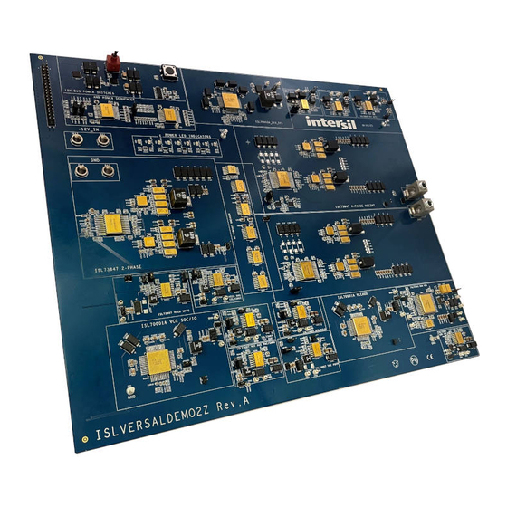
Page 15: Board Design
Layout Guidelines The general layout of the ISLVERSALDEMO2Z board is shown below. In the middle right of the board is the 0.8V/100A rail for the Versal ACAP core rail. The bottom half of the board contains the digital and DDR4 supply rails. - Page 16 VCC_AUX ISL70001A ISL73007 VCC_SOC/IO ISL73007 ISL73007 VCCAUXP PSFP MC/SMON Figure 17. ISLVERSALDEMO2Z Board Layout For the ISLVERSALDEMO2Z schematic diagram, bill of materials, and board layout files, download the design files from the website. R34UZ0015EU0102 Rev.1.02 Page 16 Feb 7, 2024...
-
Page 17: Typical Performance Graphs
ISLVERSALDEMO2Z Demonstration Board Manual Typical Performance Graphs Figure 18. Power-Up Sequencing, Ch1-8 Figure 19. Power-Down Sequencing, Ch1-8 Figure 20. Power-Up Sequencing, Ch9-16 Figure 21. Power-Down Sequencing, Ch9-16 Figure 22. ISL73847_VCCINT Rail 46A Load Step Figure 23. ISL73007_VCCO_XPIO Rail 3A load step with Transient with ±17mV Compliance Window... - Page 18 ISLVERSALDEMO2Z Demonstration Board Manual Figure 24. ISL73007_VCC_PSFP Rail 1.33A load step Figure 25. ISL70001A_VCC_SOC_IO Rail 1.6A load step with ±17mV Compliance Window with ±17mV Compliance Window Shown Figure 26. ISL70001A_VCC_AUX Rail 1.5A load step Figure 27. ISL73007_VCCO_50x Rail Steady State Ripple with ±30mV Compliance Window Shown...
- Page 19 ISLVERSALDEMO2Z Demonstration Board Manual Figure 30. ISL73007_VCC_PMC Rail Steady State Ripple Figure 31. ISL70001A_VCC_AUX Rail Steady State at 0.5A with ±17mV Compliance Window Shown Ripple at 4.2A with ±30mV Compliance Window Shown Figure 32. ISL73007_VCC_PSLP Rail Steady State Figure 33. ISL73007_VCC_PSFP Rail Steady State Ripple at 0.5A with ±17mV Compliance Window Shown...
- Page 20 ISLVERSALDEMO2Z Demonstration Board Manual Figure 36. ISL73007_GTY_AVCC Rail Steady State Figure 37. ISL73007_GTY_AVCC_AUX Rail Steady State Ripple at 1.7A with 10mVpp Compliance Window Shown Ripple at 0.5A with 10mVpp Compliance Window Shown Figure 38. ISL73007_GTY_AVTT Rail Steady State Ripple Figure 39. Current Sharing Accuracy of 4-Phase at 2.8A with 10mVpp Compliance Window Shown...
-
Page 21: Ordering Information
ISLVERSALDEMO2Z Demonstration Board Manual Ordering Information Part Number Description ISLVERSALDEMO2Z Power Management Demonstration Board Revision History Revision Date Description 1.02 Feb 7, 2024 Updated Power Tree section. 1.01 Jul 27, 2023 Corrected feature bullet. 1.00 Jun 13, 2023 Initial release R34UZ0015EU0102 Rev.1.02... - Page 22 IMPORTANT NOTICE AND DISCLAIMER RENESAS ELECTRONICS CORPORATION AND ITS SUBSIDIARIES (“RENESAS”) PROVIDES TECHNICAL SPECIFICATIONS AND RELIABILITY DATA (INCLUDING DATASHEETS), DESIGN RESOURCES (INCLUDING REFERENCE DESIGNS), APPLICATION OR OTHER DESIGN ADVICE, WEB TOOLS, SAFETY INFORMATION, AND OTHER RESOURCES “AS IS” AND WITH ALL FAULTS, AND DISCLAIMS ALL WARRANTIES, EXPRESS OR IMPLIED, INCLUDING, WITHOUT LIMITATION, ANY IMPLIED WARRANTIES OF MERCHANTABILITY, FITNESS FOR A PARTICULAR PURPOSE, OR NON-INFRINGEMENT OF THIRD-PARTY INTELLECTUAL PROPERTY RIGHTS.
Need help?
Do you have a question about the ISLVERSALDEMO2Z and is the answer not in the manual?
Questions and answers