Table of Contents
Advertisement
Advertisement
Table of Contents

Related Manuals for Bally ALPHA 2 Pro Wave


Summary of Contents for Bally ALPHA 2 Pro Wave
- Page 1 ALPHA 2 Pro™ Wave Operator’s Instruction Manual MKT-AH-1CC40ST [A]...
- Page 2 The following trademarks are owned or used under license by Bally Technologies: ALPHA 2 Pro™ Wave, Alpha Game Platform™, Alpha Pro™, Pro Series™, Bally Gaming™, and the Bally Logo™. All other product names and trademarks are the intellectual property of their respective owners.
-
Page 3: Table Of Contents
ALPHA 2 Pro™ Wave Operator’s Instruction Manual Contents Overview ..........1 Prerequisites . - Page 4 ALPHA 2 Pro™ Wave Operator’s Instruction Manual Circuit Board Reference ....... . . 29 Power Backplane Board (PCA212319-0-0) .
-
Page 5: Overview
ALPHA 2 Pro™ Wave Operator’s Instruction Manual Overview This document provides operating instructions for the ALPHA 2 Pro™ Wave (AH-1CC40ST). Your machine displays only the features supported by your software version, jurisdiction, and machine configuration. All features do not display on every machine. If any feature does not apply to your machine, then go to the next section. -
Page 6: Required Items
ALPHA 2 Pro™ Wave Cables and Boards • Service • Gaming Machine Concepts • Glossary NOTE Download online manuals at www.ballytech.com. Order manuals at 1 877-GO BALLY (462 2559). Outside the United States, call +1 702 584 7755. MKT-AH-1CC40ST [A]... -
Page 7: Electrical Specifications
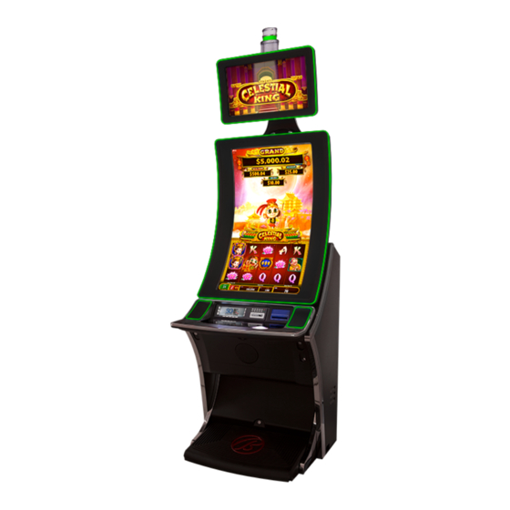
ALPHA 2 Pro™ Wave Operator’s Instruction Manual Electrical Specifications NOTE Typical currents are provided for reference only. Actual current use will depend upon machine configuration and addition of supplemental equipment such as, but not limited to, the following: systems monitoring equipment, progressive equipment, and service equipment. - Page 8 ALPHA 2 Pro™ Wave Operator’s Instruction Manual Physical Specifications Description Wave Cabinet Cabinet Image Weight Weight (Uncrated including 163.04 kg Flammable Weight) (362.30 lbs) Flammable Weight 33.97 kg (75.48 lbs) Dimensions Stand Height for Machines with Specialty Top Boxes (Recommended) Width 71.36 cm (28.09 in.)
-
Page 9: Dimensions
ALPHA 2 Pro™ Wave Operator’s Instruction Manual Dimensions Wave Front View MKT-AH-1CC40ST [A]... -
Page 10: Wave Side View
ALPHA 2 Pro™ Wave Operator’s Instruction Manual Wave Side View MKT-AH-1CC40ST [A]... -
Page 11: Unpacking And Inspecting The Machine
STEP 9. Reseat the flash media in the sockets if necessary. STEP 10. If the machine is damaged or any parts are missing, then please contact your Bally Technologies Distributor or Customer Service Representative for Return Merchandise Authorization (RMA) information. -
Page 12: Lock And Cam Specifications
ALPHA 2 Pro™ Wave Operator’s Instruction Manual Lock and Cam Specifications Lock Location Illustration Part Number Upper Door Lock (Right Turn) 237902 Optional Upper Door 237904 Secondary Lock (Right Turn) Cam Middle Door Lock (Left 237627 Turn) Optional Middle Door 237904 Secondary Lock (Left Turn) Lower Door Lock (DROP) -
Page 13: Door And Lock Locations - Wave
ALPHA 2 Pro™ Wave Operator’s Instruction Manual Door and Lock Locations - Wave Upper Door Upper Door Lock Audit Key Switch Middle Door Middle Deck Door Door Lock (not shown) Lower Door Lock Lower Door MKT-AH-1CC40ST [A]... -
Page 14: Opening And Closing Doors
ALPHA 2 Pro™ Wave Operator’s Instruction Manual Opening and Closing Doors Use the following instructions to ensure safe and correct operation of door equipment: • Secure doors with locks installed according to instructions from your lock manufacturer. • Inspect door latches, brackets, pins, hinges, and gas springs (if applicable) for wear or damage, and replace, if necessary. -
Page 15: Accessing The Upper Door
ALPHA 2 Pro™ Wave Operator’s Instruction Manual Accessing the Upper Door STEP 1. To open the upper door, turn the upper right lock of the middle door clockwise, then lift the upper door. CAUTION This door rises automatically on gas springs. To prevent injury or damage, hold the door firmly. -
Page 16: Accessing The Lower Door
ALPHA 2 Pro™ Wave Operator’s Instruction Manual Accessing the Lower Door STEP 1. To open the lower door, turn the lower door lock clockwise and lift the door. Hinges hold the door open. STEP 2. To close the lower door, press down on the door until it connects to the cabinet frame, then lift and push to close the door. -
Page 17: Accessing The Deck Door
ALPHA 2 Pro™ Wave Operator’s Instruction Manual Accessing the Deck Door CAUTION The deck door is not attached to the cabinet. To prevent injury or damage, hold the center of the security panel firmly. STEP 1. To open the deck door, unfasten two screws located under the iDeck using a Phillips head screw driver and save the screws for future use. -
Page 18: Accessing The Security Panel
ALPHA 2 Pro™ Wave Operator’s Instruction Manual Accessing the Security Panel STEP 1. To open the security panel, open the middle door. See “Accessing the Middle Door” on page 10. STEP 2. Locate the security panel latch behind the deck. CAUTION This door opens downward. -
Page 19: Installing The Upper Door
ALPHA 2 Pro™ Wave Operator’s Instruction Manual STEP 4. To close the security panel, route any cables where they will not be pinched, and insert the security panel up into the cabinet from under the button deck area until the door connects to the cabinet frame securely. CAUTION To ensure wires and cables are not pinched, abraded, or otherwise damaged, use care when... - Page 20 ALPHA 2 Pro™ Wave Operator’s Instruction Manual STEP 2. Remove the upper door struts by unfastening the door strut brackets using a nut driver and save the fasteners for future use. CAUTION The door is heavy. To prevent injury or damage, have a technician hold each side of the upper door firmly.
- Page 21 ALPHA 2 Pro™ Wave Operator’s Instruction Manual STEP 3. Align the holes of the monitor with the holes of the monitor hinge, secure it with eight screws, and continue holding the monitor. CAUTION The upper door is not attached to the cabinet. To prevent injury or damage, have a technician hold each side of the upper door firmly.
- Page 22 ALPHA 2 Pro™ Wave Operator’s Instruction Manual STEP 5. Align the holes of the door struts with the holes of the provided door brackets and secure with a clevis pin. CAUTION The gas springs are not attached to the cabinet. To prevent injury or damage, hold the struts during installation.
-
Page 23: Removing The Upper Door
ALPHA 2 Pro™ Wave Operator’s Instruction Manual Removing the Upper Door CAUTION The upper door is large and heavy. To prevent injury or damage, enlist the aid of another technician during removal. STEP 1. Disconnect all cabling connecting the cabinet to power sources. - Page 24 ALPHA 2 Pro™ Wave Operator’s Instruction Manual STEP 6. Remove eight screws securing the upper door to the cabinet and save for future use. MKT-AH-1CC40ST [A]...
-
Page 25: Removing The Mpu
ALPHA 2 Pro™ Wave Operator’s Instruction Manual Removing the MPU STEP 1. Open the upper door. STEP 2. Locate the MPU on the left side of the cabinet. STEP 3. Turn the thumbscrew counterclockwise to unfasten the MPU cover plate and pull the plate towards the center of the cabinet. -
Page 26: Installing The Mpu
ALPHA 2 Pro™ Wave Operator’s Instruction Manual Installing the MPU STEP 1. Open the upper door and open the MPU cover plate. STEP 2. Insert the MPU into the provided MPU bracket by lowering, leaning it forward, then lowering into the connectors. -
Page 27: Installing The Machine
ALPHA 2 Pro™ Wave Operator’s Instruction Manual Installing the Machine STEP 1. Ensure the new location has appropriate power and network cabling installed. NOTE Changes in floor configuration may require reconfiguring and rerunning of new power and CAT-5 cables. STEP 2. Use the instructions provided by your lock manufacturer to install locks in appropriate areas. - Page 28 ALPHA 2 Pro™ Wave Operator’s Instruction Manual STEP 4. Place the machine at the desired location. CAUTION Ensure the sides and back of the cabinet are not exposed or accessible by players. • Do not place the machine on any wires or cables. •...
- Page 29 ALPHA 2 Pro™ Wave Operator’s Instruction Manual STEP 5. Securely fasten the machine to the stand and, if applicable, adjacent cabinet or wall. STEP 6. Connect and route the power and network cables where they will not be pinched, abraded, or otherwise damaged.
-
Page 30: Operational Tasks
ALPHA 2 Pro™ Wave Operator’s Instruction Manual Operational Tasks Attendant Pays and Cancelling Credits NOTE For more information on event and error messages and solutions, see your Alpha Game Platform™ Software Setup and Operation guide. Messages similar to the following require an Attendant to release the lockup by turning a key in the audit key switch: •... -
Page 31: Collecting Bills From The Machine
ALPHA 2 Pro™ Wave Operator’s Instruction Manual Collecting Bills from the Machine NOTE Bill acceptor cash box collection procedures depend upon the machine model specification, added equipment and the jurisdiction. Note that bill acceptor cash boxes may vary depending upon the manufacturer and may include a cash box release mechanism. -
Page 32: Refilling The Printer Paper
ALPHA 2 Pro™ Wave Operator’s Instruction Manual Refilling the Printer Paper NOTE Printer paper refill procedures depend upon the machine model specification, added equipment, and the jurisdiction. CAUTION Complete your site’s procedures for accessing the machine. Obtain appropriate coupon paper and ensure the coupon paper matches the machine’s coupon printer size and capacity. -
Page 33: Circuit Board Reference
ALPHA 2 Pro™ Wave Operator’s Instruction Manual Circuit Board Reference For reference only. See your Parts book for parts specific to your machine. Power Backplane Board (PCA212319-0-0) Connectors for Power Backplane Board (PCA212319-0-0) Connector Usage J1 SURGE JUMPER Surge Jumper Connector J2 SWITCH CONNECTOR —... - Page 34 ALPHA 2 Pro™ Wave Operator’s Instruction Manual Connectors for Power Backplane Board (PCA212319-0-0) Connector Usage J12 RCU POWER RCU Power Connector J13 DC POWER BULKHEAD DC Power for the Bulkhead J14 MPU BACKPLANE MPU Backplane Connector J15 7-SEG DISP METER, POWER 7-Segment Display Meter Power AND PAYLINE and Payline Power...
-
Page 35: Signal Backplane Board, Alpha 2 (Pca235204-0-0)
ALPHA 2 Pro™ Wave Operator’s Instruction Manual Signal Backplane Board, ALPHA 2 (PCA235204-0-0) MKT-AH-1CC40ST [A]... - Page 36 ALPHA 2 Pro™ Wave Operator’s Instruction Manual Connectors for Signal Backplane Board, ALPHA 2 (PCA235204-0-0) Connector Usage Battery for memory retention when the power is off J1 SERVICE LIGHT Service Light Connector J3 SYSTEMS Systems Connector J4 POWER INTERFACE Power Backplane Connector J5 ATTEND.
-
Page 37: Lighting Control Unit (Lcu) Board (Pca235737-0-0)
ALPHA 2 Pro™ Wave Operator’s Instruction Manual Lighting Control Unit (LCU) Board (PCA235737-0-0) Port 7 Port 4 Port 6 Port 3 Port 5 Port 2 Port 1 Port 0 Power MKT-AH-1CC40ST [A]... -
Page 38: Lcu Board Dip Switch Settings
Coin tray light or other simple device Port 6 Coin tray light or other simple device Port 7 Bally logo light, red DIP Switch for manually setting light colors LCU to MPU communication cable connector LCU Board DIP Switch Settings... - Page 39 ALPHA 2 Pro™ Wave Operator’s Instruction Manual Light Control Unit (LCU) Diagnostics Light Pattern Description Each light fades from red to The machine is in a diagnostic mode. orange, yellow, green, blue, Typically, the diagnostic mode displays indigo, and violet, one at a upon powering on.
- Page 40 ALPHA 2 Pro™ Wave Operator’s Instruction Manual LCU Board LED Indicator Light (D2) Indicator Button Description Deck State Off-line One of the following error conditions may exist: the power is off; the power cable is unplugged; a firmware error exists; a hardware error exists;...
-
Page 41: Cable Connector And Flash Media
ALPHA 2 Pro™ Wave Operator’s Instruction Manual Cable Connector and Flash Media Socket Reference For reference only. See your Cables and Boards book for cables specific to your machine. ALPHA 2.1 MPU Assembly (226458) Display Port Video Interface, Secondary (top monitor) Display Port Video Interface, Touchscreen, Primary Primary (bottom monitor) -
Page 42: Cabinet Signal Cable (236492-00-0)
ALPHA 2 Pro™ Wave Operator’s Instruction Manual Cabinet Signal Cable (236492-00-0) This cable includes wiring for some systems connections. If your system requires a customized cable, then disconnect the systems connectors on this cable. Cabinet Signal Cable - Systems Interconnect Pin-Outs Color Description Yellow/Grey... -
Page 43: Cabinet Signal Cable - Systems Interconnect Segment With
ALPHA 2 Pro™ Wave Operator’s Instruction Manual Cabinet Signal Cable - Systems Interconnect Segment with Pin-Out View If your system equipment requires a customized cable, then use the following diagram to identify and disconnect the appropriate systems connectors. MKT-AH-1CC40ST [A]... - Page 44 ALPHA 2 Pro™ Wave Operator’s Instruction Manual This page is intentionally blank. MKT-AH-1CC40ST [A]...
Need help?
Do you have a question about the ALPHA 2 Pro Wave and is the answer not in the manual?
Questions and answers