Table of Contents
Advertisement
Quick Links
Advertisement
Table of Contents

Subscribe to Our Youtube Channel
Related Manuals for Redarc ICMS-010


Summary of Contents for Redarc ICMS-010
- Page 1 ICMS‑010 Integrated Module, 12 V, 2000 W Inverter, 30 A Charger MODEL: ICMS‑010 ƒ...
- Page 2 The ICMS‑010 has been engineered to serve the unique power needs of off‑road enthusiasts and adventurers, with all of REDARC's most trusted power devices in one integrated system. The system seamlessly integrates into vehicle canopies, providing a convenient and compact hub for powering your outdoor adventures.
-
Page 3: Table Of Contents
CONTENTS WARNINGS & SAFETY INSTRUCTIONS ..................OVERVIEW ............................Kit Contents ............................Parts of the ICMS‑010 ........................INSTALLATION — MOUNTING ......................Mounting Checklist — Before You Begin .................... Mounting the ICMS‑010 ........................Mounting the Display .......................... INSTALLATION — WIRING ....................... Wiring Diagram — As Supplied ...................... -
Page 4: Warnings & Safety Instructions
REDARC recommends that the products referenced in this manual be installed by a suitably qualified person. Disclaimer: REDARC accepts no liability for any injury, loss or property damage which may occur from the improper or unsafe installation or use of its products. - Page 5 11. NEVER smoke or allow a spark or flame in vicinity of battery or engine. 12. Remove personal metal items such as rings, bracelets, necklaces, and watches before working with a vehicle battery. A vehicle battery can produce a short‑circuit current high enough to weld a ring or the like to metal, causing a severe burn.
-
Page 6: Overview
OVERVIEW ICMS-010 BMS1230S3R R-12-2000RS3 KIT CONTENTS Ref. Part Qty. ICMS‑010 Integrated Module, 12 V, 2000 W, 30 A Drawstring Bag Panel Mount Cable Ties Cable Ties 250 A MEGA Fuse 100 A MIDI Fuse 50 A MIDI Fuse 15 A Blade Fuse 10 A Blade Fuse 5 A Blade Fuse ICMS‑010 Mounting Template... -
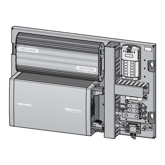
Page 7: Parts Of The Icms-010
(×4) (×3) PARTS OF THE ICMS‑010 Ref. Part Mounting Panel Mounting Points ×4 Cable Ducts (with removable covers, not shown) Cable Tie Mounting Holes ×3 Manager 30 (BMS1230S3) BMS Connector RS3 Pure Sine Wave Inverter 12 V, 2000 W (R‑12‑2000RS3) Earth Bond Cable Fuse Box (12 circuit. -
Page 8: Installation - Mounting
INSTALLATION — MOUNTING Risk of electric shock. Do not expose the ICMS‑010 to rain, snow, spray, liquid, or dust. Doing so WARNING: may result in damage to the Inverter and other appliances installed in the system or result in electric shock or fire. CAUTION Lifting a heavy object can cause muscle strain or back injury. -
Page 9: Mounting The Icms-010
MOUNTING THE ICMS‑010 RECOMMENDED FASTENERS The following fasteners are recommended for secure and safe mounting of the ICMS‑010. If you choose to use alternative fasteners, make sure they are equivalent. High‑tensile bolt × 4 M8 (5/16") — metric class 8.8 or imperial grade 5 minimum. Length determined by mounting surface thickness. -
Page 10: Installation - Wiring
INSTALLATION — WIRING Before beginning installation, read ALL Warnings and Safety Information in the supplied Manager 30 WARNING: and RS3 Inverter instruction manuals. WIRING DIAGRAM — AS SUPPLIED The following wiring diagram shows the ICMS‑010 in its as‑supplied state with pre‑wired connections (excluding the Display). -
Page 11: Wiring Diagram - Typical Setup
Auxiliary Battery Battery *1 REDARC RS3WK‑002 Inverter Wiring Kit recommended. *2 REDARC FK50 50 A Fuse Kit recommended. *3 For input cable sizing/cross sectional area for the power input cable, refer to 'Power Input Cable Size Selection' (page 14). *4 Insert each fuse once wiring is complete. Ensure each fuse is adequate for the cable size it protects. -
Page 12: Wiring Steps
WIRING STEPS WHAT YOU WILL NEED Before you begin, purchase the correct cable sizes, lugs, fuses, and consumables needed for your installation. Note: Poor quality cable can degrade over time posed to high temperatures (such as in an engine bay). Make sure you purchase good‑quality cable with a suitable temperature rating for your installation. -
Page 13: Connect The Auxiliary Battery
DO NOT connect the auxiliary battery to the low current fuses (50 A and 100 A Fuse). Purchasing the REDARC RS3WK‑002 Inverter Wiring Kit for this connection is recommended. The lugs, 300 A fuse and fuse holder are pre‑assembled for quick and easy installation. -
Page 14: Connect The Start Battery
"Power Input Cable Size Selection". The REDARC FK50 50 A Fuse Kit is recommended for fusing this connection. Note: Poor quality cable can degrade over time when exposed to high temperatures (such as in an engine bay). Make sure you purchase good‑quality cable with a suitable temperature rating for your installation. -
Page 15: Connect The Redvision Display To The Manager
Chassis Ground 1.7 N·m ± 10% 1.25 lbf·ft ± 10% Manager (BMS1230S3) Solar Panel (12 V Nominal) Negative Busbar (ICMS-010) 3.6 N·m ± 10% 2.66 lbf·ft ± 10% To A or B Optional Connector (e.g. Anderson) Installation — Wiring | 15... -
Page 16: Connect Auxiliary Loads
8. CONNECT AUXILIARY LOADS Connect typical loads, including auxiliary lights, pumps, fridge, cig/accessory socket, USB chargers, small air compressors etc. Select cable sizing and fuse ratings that meet the device manufacturers specification. Purchase the correct cable size needed for the devices in your system, as well as M4 (#8) ring terminals that meet the following criteria: they are the correct diameter for the cable you have selected (10–16 AWG (6–1.5 mm²), and;... -
Page 17: Strain-Relief And Cable Management
STRAIN‑RELIEF AND CABLE MANAGEMENT Do not route cables over hot surfaces and sharp objects, or over/through parts of the vehicle that CAUTION: move during operation or maintenance. PROTECT AND SECURE THE CABLES Once all wiring is completed, do the following to protect and secure the cables: Route all cabling through the Cable Ducts then replace the Cable Duct Covers. -
Page 18: Technical Specifications
TECHNICAL SPECIFICATIONS For the individual technical specifications for the Manager 30 (including RedVision Display) and the RS3 Inverter, refer to the supplied instruction manuals. Specifications subject to change without notice. PHYSICAL SPECIFICATIONS Weight 18.4 kg (40.6 lb) Dimensions 659 × 450 × 152 mm (25.95" × 17.72" × 5.98") THERMAL SPECIFICATIONS Ideal Operating Temperature Range –20 ~ +40°C / –4 ~ +104°F (derates up to 60°C/140°F) -
Page 19: Warranty
REDARC Electronics Pty Ltd, 23 Brodie Road (North), Lonsdale SA 5160, Australia. Design, product configuration and technical specifications are subject to change without notice. | Copyright © 2023 REDARC Electronics Pty Ltd. All rights reserved. REDARC® and THE POWER OF REDARC® are trademarks of REDARC Electronics Pty Ltd. - Page 20 Tech Support 1300 REDARC (1300‑733‑272) Australia +61 8 8322 4848 New Zealand +64 9 222 1024 UK & Europe +44 (0)20 3930 8109 +1 (704) 247‑5150 Canada +1 (604) 260‑5512 Mexico +52 (558) 526‑2898 redarcelectronics.com INST256‑2...
Need help?
Do you have a question about the ICMS-010 and is the answer not in the manual?
Questions and answers