Table of Contents
Advertisement
Quick Links
Fluidcontrol
Fluidcontrolterminal FCT
Installation and Operation Instructions
Original instructions
BE100006
Bühler Technologies GmbH, Harkortstr. 29, D-40880 Ratingen
02/2022
Tel. +49 (0) 21 02 / 49 89-0, Fax: +49 (0) 21 02 / 49 89-20
E-Mail: fluidcontrol@buehler-technologies.com
Internet: www.buehler-technologies.com
Advertisement
Table of Contents

Related Manuals for Bühler technologies FCT


Summary of Contents for Bühler technologies FCT
- Page 1 Fluidcontrol Fluidcontrolterminal FCT Installation and Operation Instructions Original instructions BE100006 Bühler Technologies GmbH, Harkortstr. 29, D-40880 Ratingen 02/2022 Tel. +49 (0) 21 02 / 49 89-0, Fax: +49 (0) 21 02 / 49 89-20 E-Mail: fluidcontrol@buehler-technologies.com Internet: www.buehler-technologies.com...
- Page 2 Bühler Technologies GmbH, Harkortstr. 29, D-40880 Ratingen Tel. +49 (0) 21 02 / 49 89-0, Fax: +49 (0) 21 02 / 49 89-20 Internet: www.buehler-technologies.com E-Mail: fluidcontrol@buehler-technologies.com Read this instruction carefully prior to installation and/or use. Pay at- tention particularly to all advises and safety instructions to prevent in- juries.
-
Page 3: Table Of Contents
Fluidcontrolterminal FCT Contents Introduction ............................................. 2 Intended Use......................................... 2 Product Description...................................... 2 Model Key .......................................... 3 Scope of Delivery........................................ 3 Safety instructions ......................................... 4 Important advice ......................................... 4 General hazard warnings .................................... 5 Transport and storage ........................................ 6 4 Installation and connection ...................................... 7 Installation .......................................... -
Page 4: Introduction
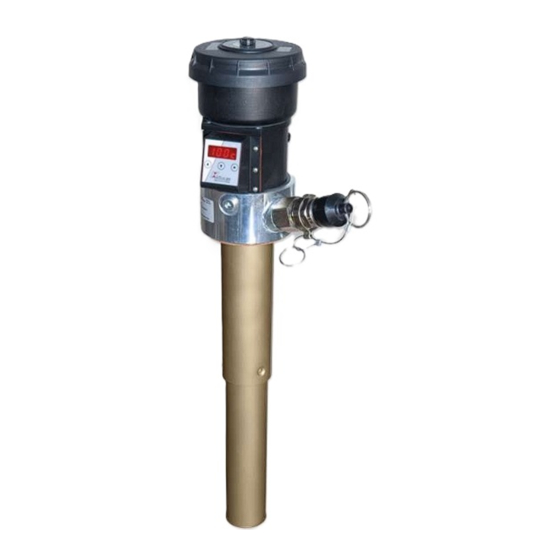
Fluidcontrolterminal FCT 1 Introduction 1.1 Intended Use The fluid control terminal is a compact adapter flange with several connection options for individual applications. The design of the fluid control terminal allows for flexible equipment so the device can easily be adapted to the requirements of the specific application. -
Page 5: Model Key
Fluidcontrolterminal FCT 1.3 Model Key FCT-G3/4- Option 2: Filling port Type designation/port Type: Walther (DN 19) Length (max. 1420 mm) Type: Stäubli (DN 11) Dummy plug Option 3: Vacuum switch Variable (please specify) Vacuum switch (elec.) Dummy plug Option 1: Sampling port... -
Page 6: Safety Instructions
Fluidcontrolterminal FCT 2 Safety instructions 2.1 Important advice Operation of the device is only permitted if: – the product is used under the conditions described in the installation- and operation instruction, the intended application according to the type plate and the intended use. In case of unauthorized modifications done by the user Bühler Technolo- gies GmbH can not be held responsible for any damage, –... -
Page 7: General Hazard Warnings
Fluidcontrolterminal FCT 2.2 General hazard warnings The equipment must be installed by a professional familiar with the safety requirements and risks. Be sure to observe the safety regulations and generally applicable rules of technology relevant for the installation site. Prevent malfunctions and avoid personal injuries and property damage. -
Page 8: Transport And Storage
Fluidcontrolterminal FCT 3 Transport and storage Only transport the product inside the original packaging or a suitable alternative. The equipment must be protected from moisture and heat when not in use. It must be stored in a covered, dry, dust-free room at room temperature. -
Page 9: Installation And Connection
Fluidcontrolterminal FCT 4 Installation and connection DANGER Electric voltage Risk of electric shock a) Always disconnect the unit from the mains before performing work. b) Secure the equipment from accidental restarting. c) The equipment may only be installed, maintained and put into operation by instruc- ted, competent personnel. -
Page 10: Information On The Correct Operation Of Reed Contacts In Bühler Level Switches
Fluidcontrolterminal FCT 4.3 Information on the correct operation of reed contacts in Bühler level switches Based on their construction, reed contacts are very long lasting and reliable components. Yet the following should be considered when using them: Life of reed switches The life of reed switches can be up to 10 cycles. -
Page 11: Vacuum Switch Electrical Connection
Fluidcontrolterminal FCT 4.4 Vacuum Switch Electrical Connection An optional vacuum switch or dummy plug may be installed. The vacuum switch is equipped with a snap-action switch to only switch signals when the full limits are reached continuously. NOTICE! With the filling and ventilation adapter, only the vacuum switch requires electrical start-up. -
Page 12: Operation And Control
Fluidcontrolterminal FCT 5 Operation and control 5.1 Level Switch The following level switches are available for the fluid control terminal: – NV 77/NV 77D – NV 74/NV 74D – NV 73 – NV 71 For additional information on the built-in level switch, please refer to the operating instructions included with the level switch. -
Page 13: Manual Filling
Fluidcontrolterminal FCT 5.3 Manual Filling There are two types of connections for filling: A Stäubli receptacle and a Walther coupler. Oil can be added manually via these ports. Stäubli SBA 11/CN (receptacle) with G3/4 to G1/2 reducer 64.5 Walther MD-019 (filling coupler) BE100006 ◦... -
Page 14: Maintenance And Repair
Fluidcontrolterminal FCT 6 Maintenance and repair 6.1 Filter Change DANGER Toxic, corrosive media The media used can be harmful to the health. a) If necessary, ensure the medium is discharged safely. b) Use protection when handling toxic/acidic mediums. Wear suitable protective equip- ment. -
Page 15: Service And Repair
Fluidcontrolterminal FCT 7 Service and repair This chapter contains information on troubleshooting and correction should an error occur during operation. Repairs to the unit must be performed by Bühler authorised personnel. Please contact our Service Department with any questions: Tel.: +49-(0)2102-498955 or your agent If the equipment is not functioning properly after correcting any malfunctions and switching on the power, it must be inspected by the manufacturer. -
Page 16: Disposal
Fluidcontrolterminal FCT 8 Disposal The applicable national laws must be observed when disposing of the products. Disposal must not result in a danger to health and environment. The crossed out wheelie bin symbol on Bühler Technologies GmbH electrical and electronic products indicates special disposal notices within the European Union (EU). -
Page 17: Appendices
Fluidcontrolterminal FCT 9 Appendices 9.1 Technical Data Basic data Dimensions Operating pressure: max. 1 bar Optical analogue vacuum Operating temperature: max. +80 °C indicator display range 0.35 bar (optional) Weight at L = 500 mm: approx. 5 kg Level switch... -
Page 18: Airflow/Back Pressure Table
Fluidcontrolterminal FCT 9.2 Airflow/Back Pressure Table Airflow - Back pressure - Table fluid control terminal with SM-L filter with MIC filter L/min Bühler Technologies GmbH BE100006 ◦ 02/2022... -
Page 19: Attached Documents
Fluidcontrolterminal FCT 10 Attached documents – Declaration of Conformity KX100024 – RMA - Decontamination Statement BE100006 ◦ 02/2022 Bühler Technologies GmbH... - Page 22 RMA-Formular und Erklärung über Dekontaminierung RMA-Form and explanation for decontamination RMA-Nr./ RMA-No. Die RMA-Nr. bekommen Sie von Ihrem Ansprechpartner im Vertrieb oder Service. Bei Rücksendung eines Altgeräts zur Entsorgung tragen Sie bitte in das Feld der RMA-Nr. "WEEE" ein./ You may obtain the RMA number from your sales or ser- vice representative.
- Page 23 Dekontaminierungserklärung DE000011 Bühler Technologies GmbH, Harkortstr. 29, D-40880 Ratingen 12/2022 Tel. +49 (0) 21 02 / 49 89-0, Fax: +49 (0) 21 02 / 49 89-20 E-Mail: service@buehler-technologies.com Internet: www.buehler-technologies.com...
Need help?
Do you have a question about the FCT and is the answer not in the manual?
Questions and answers