Table of Contents
Advertisement
Quick Links
50VG-K
Performance™ 15.2+ SEER2 2-Stage Packaged Air
Conditioner System
with Puron® (R-410A) Refrigerant
Single and Three Phase
2-5 Nominal Tons (Sizes 24-60)
IMPORTANT: Effective January 1, 2015, all split system and packaged
air conditioners must be installed pursuant to applicable regional
efficiency standards issued by the Department of Energy.
NOTE: Read the entire instruction manual before starting the
installation.
NOTE: Installer: Make sure the Owner's Manual and Service
Instructions are left with the unit after installation.
Table of Contents
Table of Contents . . . . . . . . . . . . . . . . . . . . . . . . . . . . . . . . . . . . . . . . 1
Safety Considerations . . . . . . . . . . . . . . . . . . . . . . . . . . . . . . . . . . . . . 1
Introduction. . . . . . . . . . . . . . . . . . . . . . . . . . . . . . . . . . . . . . . . . . . . . 2
Receiving and Installation . . . . . . . . . . . . . . . . . . . . . . . . . . . . . . . . . 2
Identify Unit . . . . . . . . . . . . . . . . . . . . . . . . . . . . . . . . . . . . . . . . 2
Inspect Shipment. . . . . . . . . . . . . . . . . . . . . . . . . . . . . . . . . . . . . 2
Roof Curb . . . . . . . . . . . . . . . . . . . . . . . . . . . . . . . . . . . . . . . . . . 2
Slab Mount . . . . . . . . . . . . . . . . . . . . . . . . . . . . . . . . . . . . . . . . . 3
Inspection . . . . . . . . . . . . . . . . . . . . . . . . . . . . . . . . . . . . . . . . . . 8
Configuring Units for Downflow (vertical) Discharge. . . . . . . . 9
High-Voltage Connections . . . . . . . . . . . . . . . . . . . . . . . . . . . . 10
Special Procedures for 208-V Operation . . . . . . . . . . . . . . . . . 11
Control Voltage Connections . . . . . . . . . . . . . . . . . . . . . . . . . . 11
Standard Connection. . . . . . . . . . . . . . . . . . . . . . . . . . . . . . . . . 11
Transformer Protection . . . . . . . . . . . . . . . . . . . . . . . . . . . . . . . 11
Pre-Start-up . . . . . . . . . . . . . . . . . . . . . . . . . . . . . . . . . . . . . . . . . . . . 13
Start-up . . . . . . . . . . . . . . . . . . . . . . . . . . . . . . . . . . . . . . . . . . . . . . . 13
Checking and Adjusting Refrigerant Charge . . . . . . . . . . . . . . 14
Indoor Airflow and Airflow Adjustments . . . . . . . . . . . . . . . . 14
Cooling Sequence of Operation . . . . . . . . . . . . . . . . . . . . . . . . 15
Maintenance . . . . . . . . . . . . . . . . . . . . . . . . . . . . . . . . . . . . . . . . . . . 26
Air Filter . . . . . . . . . . . . . . . . . . . . . . . . . . . . . . . . . . . . . . . . . . 26
Indoor Blower and Motor . . . . . . . . . . . . . . . . . . . . . . . . . . . . . 26
Outdoor Coil, Indoor Coil, and Condensate Drain Pan . . . . . . 27
Outdoor Fan . . . . . . . . . . . . . . . . . . . . . . . . . . . . . . . . . . . . . . . 27
Electrical Controls and Wiring . . . . . . . . . . . . . . . . . . . . . . . . . 27
Refrigerant Circuit . . . . . . . . . . . . . . . . . . . . . . . . . . . . . . . . . . 28
Evaporator Airflow . . . . . . . . . . . . . . . . . . . . . . . . . . . . . . . . . . 28
Puron (R-410A) Items . . . . . . . . . . . . . . . . . . . . . . . . . . . . . . . 28
Pressure Switches . . . . . . . . . . . . . . . . . . . . . . . . . . . . . . . . . . . 28
Low-Pressure Switch (Air Conditioner Only) . . . . . . . . . . . . . 28
High-Pressure Switch . . . . . . . . . . . . . . . . . . . . . . . . . . . . . . . . 28
Refrigerant . . . . . . . . . . . . . . . . . . . . . . . . . . . . . . . . . . . . . . . . 28
Compressor Oil . . . . . . . . . . . . . . . . . . . . . . . . . . . . . . . . . . . . . 28
Servicing Systems on Roofs with Synthetic Materials . . . . . . . 29
Synthetic Roof Precautionary Procedure . . . . . . . . . . . . . . . . . 29
Liquid Line Filter Drier . . . . . . . . . . . . . . . . . . . . . . . . . . . . . . 29
Puron (R-410A) Refrigerant Charging . . . . . . . . . . . . . . . . . . . 29
Troubleshooting . . . . . . . . . . . . . . . . . . . . . . . . . . . . . . . . . . . . . . . . 29
Start-up Checklist . . . . . . . . . . . . . . . . . . . . . . . . . . . . . . . . . . . . . . . 29
Installation Instructions
5) . . . . . . . . . . . . . . . . . . . . . . 8
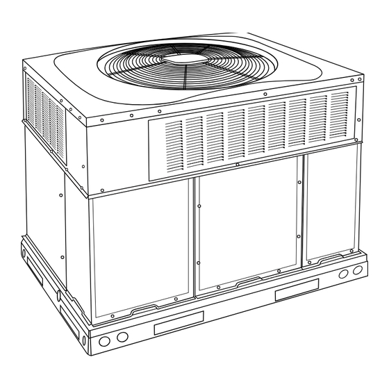
Fig. 1 - Unit 50VG-K
Safety Considerations
Improper installation adjustment, alteration, service, maintenance, or use
can cause explosion, fire, electrical shock, or other conditions which
may cause death, personal injury, or property damage. Consult a
qualified installer, service agency, or your distributor or branch for
information or assistance. The qualified installer or agency must use
factory-authorized kits or accessories when modifying this product Refer
to the individual instructions packaged with the kits or accessories when
installing.
Follow all safety codes. Wear safety glasses, protective clothing, and
work gloves. Use quenching cloth for brazing operations. Have a fire
extinguisher available. Read these instructions thoroughly and follow all
warnings or cautions included in literature and attached to the unit.
Consult local building codes, the current editions of the National
Electrical Code (NEC) NFPA 70.
In Canada refer to the current editions of the Canadian electrical Code
CSA C22.1.
Recognize safety information. This is the safety-alert symbol
you see this symbol on the unit and in instructions or manuals, be alert to
the potential for personal injury. Understand these signal words;
DANGER, WARNING, and CAUTION. These words are used with the
safety-alert symbol. DANGER identifies the most serious hazards which
will result in severe personal injury or death. WARNING signifies
hazards which could result in personal injury or death. CAUTION is
used to identify unsafe practices which may result in minor personal
injury or product and property damage. NOTE is used to highlight
A09033
. When
Advertisement
Table of Contents

Related Manuals for Carrier Performance 50VG-K


Summary of Contents for Carrier Performance 50VG-K
-
Page 1: Table Of Contents
50VG-K Performance™ 15.2+ SEER2 2-Stage Packaged Air Conditioner System with Puron® (R-410A) Refrigerant Single and Three Phase 2-5 Nominal Tons (Sizes 24-60) Installation Instructions IMPORTANT: Effective January 1, 2015, all split system and packaged air conditioners must be installed pursuant to applicable regional efficiency standards issued by the Department of Energy. -
Page 2: Introduction
50VG-K: Installation Instructions suggestions which will result in enhanced installation, reliability, or NOTICE operation. WARNING If the unit gasketing or insulation must be replaced, ensure the material used is compliant with the two agency requirements listed. ELECTRICAL SHOCK HAZARD Insulation and adhesives shall meet NFPA 90.1 requirements for flame spread and smoke generation. -
Page 3: Slab Mount
50VG-K: Installation Instructions duct openings. This kit is used when existing curb is modified by removing outer horizontal flange. CAUTION UNIT/STRUCTURAL DAMAGE HAZARD Failure to follow this caution may result in property damage. Ensure there is sufficient clearance for saw blade when cutting the outer horizontal flange of the roof curb so there is no damage to the roof or flashing. - Page 4 50VG-K: Installation Instructions A230031 Fig. 2 – 24-30 Unit Dimensions Manufacturer reserves the right to change, at any time, specifications and designs without notice and without obligations.
- Page 5 50VG-K: Installation Instructions A230032 Fig. 3 – 36-60 Unit Dimensions Manufacturer reserves the right to change, at any time, specifications and designs without notice and without obligations.
- Page 6 50VG-K: Installation Instructions SMALL/COMMON CURB SMALL SUPPLY BASE UNIT LARGE BASE RETURN UNIT UNIT PLACEMENT ON COMMON CURB SMALL OR LARGE BASE UNIT LARGE CURB A180216 UNIT CATALOG (small/common (large base) SIZE NUMBER base) IN. (mm) IN. (mm) (mm) IN. (mm) (mm) (mm) (mm)
- Page 7 50VG-K: Installation Instructions CAUTION - NOTICE TO RIGGERS PRUDENCE - AVIS AUX MANIPULATEUR ACCESS PANELS MUST BE IN PLACE WHEN RIGGING. PANNEAUX D'ACCES DOIT ÊTRE EN PLACE POUR MANIPULATION. Use top skid as spreader bar. / Utiliser la palette du haut comme barre de répartition DUCTS MINIMUM HEIGHT: 36"...
-
Page 8: Inspection
50VG-K: Installation Instructions Rigging/Lifting of Unit (See Fig. Only trained, qualified crane operators and ground support staff should handle and install this equipment. WARNING When working with this equipment, observe precautions in the literature, on tags, stickers, and labels attached to the equipment, and any other UNIT FALLING HAZARD safety precautions that might apply. -
Page 9: Configuring Units For Downflow (Vertical) Discharge
50VG-K: Installation Instructions To remove downflow return and supply knockout covers, break front and TRAP right side connecting tabs with a screwdriver and hammer. Push cover OUTLET down to break rear and left side tabs. 1-in. (25 mm) min. NOTE: These panels are held in place with tabs similar to an electrical knockout. -
Page 10: High-Voltage Connections
50VG-K: Installation Instructions CAUTION UNIT COMPONENT DAMAGE HAZARD Failure to follow this caution may result in damage to the unit being installed. Make all electrical connections in accordance with NFPA 70 (NEC) (latest edition) and local electrical codes governing such wiring. -
Page 11: Special Procedures For 208-V Operation
50VG-K: Installation Instructions Control Voltage Connections NOTE: Do not use any type of power-stealing thermostat. Unit control problems may result. Use no. 18 American Wire Gage (AWG) color-coded, insulated (35°C minimum) wires to make the control voltage connections between the thermostat and the unit. - Page 12 50VG-K: Installation Instructions Table 1 – Physical Data UNIT SIZE NOMINAL CAPACITY (ton) SHIPPING WEIGHT lb. SHIPPING WEIGHT (kg) 148.3 176.4 201.4 210.5 COMPRESSORS Scroll Quantity REFRIGERANT (R-410A) 7.05 10.8 12.1 Quantity lb Quantity (kg) REFRIGERANT METERING DEVICE OUTDOOR COIL Rows...Fins/in.
-
Page 13: Pre-Start-Up
50VG-K: Installation Instructions Pre-Start-up Start-up Step 1 – Check Cooling and Accessory Electric Heat (if WARNING applicable) Operation Start and check the unit for proper control operation as follows: ENVIRONMENTAL, FIRE, EXPLOSION, ELECTRICAL 1. Place room thermostat SYSTEM switch or MODE control in OFF SHOCK HAZARD position. -
Page 14: Checking And Adjusting Refrigerant Charge
50VG-K: Installation Instructions Indoor Airflow and Airflow Adjustments 5. Charge unit with R-410A refrigerant, using an electronic scale. Refer to unit rating plate for required charge. CAUTION Step 3 – Start-Up Adjustments Complete the required procedures given in the Pre-Start-Up section UNIT OPERATION HAZARD before starting the unit. -
Page 15: Cooling Sequence Of Operation
50VG-K: Installation Instructions Selection of Proper Fan Speeds for Operation Modes: Low Stage Cooling (All Models): Using Table 7 Table 9 find the external static pressure drops for wet coil, economizer, and filter, and add them to dry coil measured on the system. Using this total static pressure, look up Table 5 to find the airflows available at the total static... - Page 16 50VG-K: Installation Instructions Table 5 – Dry Coil Air Delivery* - Horizontal and Downflow Discharge 208/230V Models Sizes 24-60 ESP (in. W.C.) Unit Size Motor Speed Blue 0.10 0.11 0.11 0.12 0.12 0.13 0.13 Med-Low† Pink 0.11 0.12 0.13 0.13 0.13 0.14 0.14...
- Page 17 50VG-K: Installation Instructions Table 6 – Dry Coil Air Delivery* - Horizontal and Downflow Discharge 460 VAC - 3 Phase - Sizes 36-60 ESP (in. W.C.) Unit Size Motor Speed 1064 Low† Blue 0.26 0.26 0.27 0.29 0.31 0.32 0.34 0.36 0.38 0.39...
- Page 18 50VG-K: Installation Instructions Table 9 – Filter Pressure Drop Table (IN. W.C.) Cooling Standard CFM (SCFM) Filter Size in. (mm) Tons 900 1000 1100 1200 1300 1400 1500 1600 1700 1800 1900 2000 2100 2200 600-1400 CFM 12x20x1+12x20x1 0.02 0.03 0.05 0.06 0.08 0.10 0.11 0.13 (305x508x25+305x508x25) ...
- Page 19 50VG-K: Installation Instructions A12572 Fig. 12 – Connection Wiring Diagram 208/230-1-60 Manufacturer reserves the right to change, at any time, specifications and designs without notice and without obligations.
- Page 20 50VG-K: Installation Instructions A12573 Fig. 13 – Ladder Wiring Diagram 208/230-1-60 Manufacturer reserves the right to change, at any time, specifications and designs without notice and without obligations.
- Page 21 50VG-K: Installation Instructions A12574 Fig. 14 – Connection Wiring Diagram 208/230-3-60 Manufacturer reserves the right to change, at any time, specifications and designs without notice and without obligations.
- Page 22 50VG-K: Installation Instructions A12575 Fig. 15 – Ladder Wiring Diagram 208/230-3-60 Manufacturer reserves the right to change, at any time, specifications and designs without notice and without obligations.
- Page 23 50VG-K: Installation Instructions A12576 Fig. 16 – Connection Wiring Diagram 460-3-60 Manufacturer reserves the right to change, at any time, specifications and designs without notice and without obligations.
- Page 24 50VG-K: Installation Instructions A12577 Fig. 17 – Ladder Wiring Diagram 460-3-60 Manufacturer reserves the right to change, at any time, specifications and designs without notice and without obligations.
- Page 25 50VG-K: Installation Instructions A230122 Fig. 18 – Cooling Charging Chart Manufacturer reserves the right to change, at any time, specifications and designs without notice and without obligations.
-
Page 26: Maintenance
50VG-K: Installation Instructions Maintenance cooling season and twice during the heating season, or whenever the filter becomes clogged with dust and lint. To ensure continuing high performance, and to minimize the possibility Indoor Blower and Motor of premature equipment failure, periodic maintenance must be NOTE: All motors are pre-lubricated. -
Page 27: Outdoor Coil, Indoor Coil, And Condensate Drain Pan
50VG-K: Installation Instructions FAN GRILLE MOTOR MOTOR SHAFT A08505 Max Distance Between Top of Fan Grille and Bottom of Fan Blade “A” Size Fig. 19 – Fan Blade Position Inspect the drain pan and condensate drain line when inspecting the coils. -
Page 28: Refrigerant Circuit
50VG-K: Installation Instructions High-Pressure Switch with the proper electrical instrumentation. Refer to the unit wiring label when making these checkouts. The high-pressure switch is located in the discharge line and protects NOTE: Refer to the heating and/or cooling sequence of operation in against excessive condenser coil pressure. -
Page 29: Servicing Systems On Roofs With Synthetic Materials
50VG-K: Installation Instructions refrigerants. Take all necessary precautions to avoid exposure of the oil to the atmosphere. Servicing Systems on Roofs with Synthetic Materials POE (polyolester) compressor lubricants are known to cause long term damage to some synthetic roofing materials. Exposure, even if immediately cleaned up, may cause embrittlement (leading to cracking) to occur in one year or more. - Page 30 50VG-K: Installation Instructions Table 11 – Troubleshooting Chart SYMPTOM CAUSE REMEDY Power failure Call power company Fuse blown or circuit breaker tripped Replace fuse or reset circuit breaker Defective contactor, transformer or high-pressure, Replace component loss-of-charge or low-pressure switch Compressor and outdoor fan will not start Insufficient line voltage Determine cause and correct Incorrect or faulty wiring...
- Page 31 Access My Learning Center with your HVACpartners credentials at www.mlctraining.com. Please contact us a mylearning@carrier.com with questions. © 2023 Carrier. All rights reserved. Edition Date: 02/23 Catalog No: 50VG-05SI Replaces:New Manufacturer reserves the right to change, at any time, specifications and designs without notice and without obligations.
Need help?
Do you have a question about the Performance 50VG-K and is the answer not in the manual?
Questions and answers