Carrier Performance 50VR-A Installation Instructions Manual

Carrier Performance 50VR-A Installation Instructions Manual

15 seer 2 stage packaged heat pump
Hide thumbs Also See for Performance 50VR-A:

Advertisement

50VR ---A and 50VR ---C
Performancet 15 SEER 2---Stage Packaged Heat Pump
System with Puron (R ---410A) Refrigerant
Single and Three Phase
2---5 Nominal Tons (Sizes 24---60)
IMPORTANT: Effective January 1, 2015, all split system and
packaged air conditioners must be installed pursuant to applicable
regional efficiency standards issued by the Department of Energy.
NOTE:
Read the entire instruction manual before starting the
installation.
NOTE:
Installer: Make sure the Owner's Manual and Service
Instructions are left with the unit after installation.

TABLE OF CONTENTS

. . . . . . . . . . . . . . . . . . . . . . . . . . . . . . . . . . .
. . . . . . . . . . . . . . . . . . . . . . . . . . . . . . . . . .
. . . . . . . . . . . . . . . . . . . . . . . . . . . . . . . . . . . .
. . . . . . . . . . . . . . . . . . . . . . . . . . . . . . . . .
. . . . . . . . . . . . . . . . . . . . . . . . . . . . . . .
. . . . . . . . . . . . . . . . . . . . . . . . . . . . . . . . . . . . . .
. . . . . . . . . . . . . . . . . . . . . . . . . . . . . . . . . . . . .
. . . . . . . . . . . . . . . . . . . . . . . . . . . . . . . . .
. . . . . . . . . . . . . . . . . . . . . . . . . . . .
. . . . . . . . . . . . . . . . . . . . . . . . . . . . . . . . .
. . . . . . . . . . . . . . . . . . . . . . . . . . . . . . . . . . . . . .
. . . . . . . . . . . . . . . . . . . . . . . . . . . .
. . . . . . . . . . . . . . . . . . . . . . . . . . . . .
. . . . . . . . . . . . . . . . . . . . . . . . . . . . . .
. . . . . . . . . . . . . . . . . . . . . . . . . . . .
. . . . . . . . . . . . . . . . . . . . . . . . . . . . . . . . . . .
. . . . . . . . . . . . . . . . . . . . . . . . . . . . . . . . . . . . .
. . . . . . . . . . . . . . . . . . . . . . . . . . . . . .
. . . . . . . . . . . . . . . . . . . . . . . . . . . . . .
. . . . . . . . . . . . . . . . . . . . . . . . . . . . . .
. . . . . . . . . . . . . . . . . . . . . . . . . . . . . . . . . . . . . . .
. . . . . . . . . . . . . . . . . . . . . . . . . . . . . . . . .
. . . . . . . . . . . . . . . . . . . . . . . . . . .
. . . . . . . . . . . . . . . . . . . . . . . . . . . . . . . . . . .
. . . . . . . . . . . . . . . . . . . . . . . . . . . . . . . . . . . . .
. . . . . . . . . . . . . . . . . . . . . . . . . . . . . . . . . . . . . . .
. . . . . . . . . . . . . . . . . . . . . . . . . . . . . . . .
. . . . . . . . . . . . . . . . . . . . . . . . . . . . . . . . . . . . . .
. . . . . . . . . . . . . . . . . . . . . . . . . . . . . . . . . . .
Installation Instructions
. . . . . . . . . . . . . . . . . . . . . . . . .
. . . . . . . . . . . . . . . . .
. . . . . . . . . . . . . . . . . . . . . . . . . . .
. . . .
. . . . . . . . . . . . . . . . . . . . . . . . .
. . . . . . . . . . . . . . . . . . . . . . . . .
. . . . . . . . . . . . . . . .
. . . . . . . . . . . . . . . . . . . . . . . .
. . . . . . . . . .
. . . . . . . . . . . . . . . . . . . . . . . . .
. . . . . . . . . . .
. . . . . . . . . . . . .
. . . . . . . . . . . . . . . . . . . . . . . . .
. . .
PAGE
1
2
2- -10
2
2
2
2
2
2
6
6
6
7
7
7
7
SAFETY CONSIDERATIONS
8
8
Improper installation adjustment, alteration, service, maintenance,
9
or use can cause explosion, fire, electrical shock, or other
9
conditions which may cause death, personal injury, or property
9
damage. Consult a qualified installer, service agency, or your
9
distributor or branch for information or assistance. The qualified
9
installer or agency must use factory- -authorized kits or accessories
11
when modifying this product Refer to the individual instructions
11- -13
packaged with the kits or accessories when installing.
11
Follow all safety codes. Wear safety glasses, protective clothing,
11
and work gloves. Use quenching cloth for brazing operations.
12
Have a fire extinguisher available. Read these instructions
12
thoroughly and follow all warnings or cautions included in
12
literature and attached to the unit. Consult local building codes, the
13
current editions of the National Electrical Code (NEC) NFPA 70.
13
In Canada refer to the current editions of the Canadian electrical
Code CSA C22.1.
13
Recognize safety information. This is the safety- -alert symbol
13
When you see this symbol on the unit and in instructions or
13
manuals, be alert to the potential for personal injury. Understand
13
these signal words; DANGER, WARNING, and CAUTION. These
13
words are used with the safety- -alert symbol. DANGER identifies
13
the most serious hazards which will result in severe personal injury
32- -35
or death. WARNING signifies hazards which could result in
32
personal injury or death. CAUTION is used to identify unsafe
32
practices which may result in minor personal injury or product and
33
property damage. NOTE is used to highlight suggestions which
33
will result in enhanced installation, reliability, or operation.
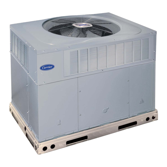
1
Fig. 1 - - Unit 50VR
. . . . . . . . . . . . . . . . . . . . .
. . . . . . . . . . . . . . . . . . . . . . . . . . . . . . .
. . . . . . . . . . . . . . . . . . . . . . . . . . . . . .
. . . . . . . . . . . . . . . . . . . . . . . . . . . . . . . .
. . . . . . . . . . . . . . . . . . . . . . . . . . . . . .
. . . . . . . . . . . . . . . . . . . . . . . . . . . .
. . . . . . . . . . . . . . . . . . . . . . . . .
. . . . . . . . . . . . . . . . . . . . . . . . . . . . . .
. . . . . . . . . . . . . . . . . . . . . . . . . . . .
A09033
33
34
34
34
35
35
35
35
35
.

Advertisement

Table of Contents
loading
Need help?

Need help?

Do you have a question about the Performance 50VR-A and is the answer not in the manual?

Questions and answers

Subscribe to Our Youtube Channel

Summary of Contents for Carrier Performance 50VR-A

  • Page 1: Table Of Contents

    50VR ---A and 50VR ---C Performancet 15 SEER 2---Stage Packaged Heat Pump System with Puron (R ---410A) Refrigerant Single and Three Phase 2---5 Nominal Tons (Sizes 24---60) Installation Instructions IMPORTANT: Effective January 1, 2015, all split system and packaged air conditioners must be installed pursuant to applicable regional efficiency standards issued by the Department of Energy.
  • Page 2: Introduction

    Step 2 — Provide Unit Support WARNING IMPORTANT: The unit must be secured to the curb by installing screws through the bottom of the curb flange and into the unit base ELECTRICAL SHOCK HAZARD rails. When installing large base units onto the common curb, the Failure to follow this warning could result in personal screws must be installed before allowing the full weight of the unit injury or death.
  • Page 3 A180108 Fig. 2 - - 50VR- -C24- -30 Unit Dimensions...
  • Page 4 A180107 Fig. 3 - - 50VR- -A36- -60 Unit Dimensions...
  • Page 5 SMALL/COMMON CURB SMALL SUPPLY BASE UNIT LARGE BASE RETURN UNIT UNIT PLACEMENT ON COMMON CURB SMALL OR LARGE BASE UNIT LARGE CURB A180216 UNIT CATALOG (small/common (large base) SIZE NUMBER base) IN. (mm) IN. (mm) (mm) IN. (mm)* (mm) (mm) (mm) (mm) IN.
  • Page 6: Provide Clearances

    CAUTION - NOTICE TO RIGGERS PRUDENCE - AVIS AUX MANIPULATEUR ACCESS PANELS MUST BE IN PLACE WHEN RIGGING. PANNEAUX D'ACCES DOIT ÊTRE EN PLACE POUR MANIPULATION. Use top skid as spreader bar. / Utiliser la palette du haut comme barre de répartition DUCTS MINIMUM HEIGHT: 36"...
  • Page 7: Inspection

    OPTIONAL OPTIONAL RETURN SUPPLY OPENING OPENING MAXIMUM ALLOWABLE DIFFERENCE in. (mm) 2˝ (6.35) (6.35) (6.35) (50.8mm) A07925 Fig. 6 - - Unit Leveling Tolerances INSPECTION EVAP. COIL COND. COIL A07926 Prior to initial use, and at monthly intervals, all rigging shackles, Fig.
  • Page 8: Configuring Units For Downflow (Vertical) Discharge

    ensure weather- -tight and airtight seal. When electric heat is duct size increases or decreases or performance may be affected. installed, use fireproof canvas (or similar heat resistant material) 6. Adequately insulate and weatherproof all ductwork located connector between ductwork and unit discharge connection. If outdoors.
  • Page 9: High- -Voltage Connections

    Three- -phase units: CAUTION 1. Run the high- -voltage (L1, L2, L3) and ground lead into the control box. UNIT COMPONENT DAMAGE HAZARD 2. Connect ground lead to chassis ground connection. Failure to follow this caution may result in damage to the 3.
  • Page 10 Table 1 – Physical Data- -Unit 50VR UNIT SIZE NOMINAL CAPACITY (ton) 2 ---1/2 3 ---1/2 SHIPPING WEIGHT lb. SHIPPING WEIGHT (kg) Scroll COMPRESSORS Quantity REFRIGERANT (R --- 410A) 11.2 11.0 14.6 12.0 14.8 Quantity lb Quantity (kg) REFRIGERANT METERING DEVICE TXV, Indoor TXV ORIFICE ID (in.)
  • Page 11: Pre- -Start- -Up

    PRE- -START- - UP START- - UP Step 1 — Check Cooling and Heating Control WARNING Operation Start and check the unit for proper control operation as follows: ENVIRONMENTAL, FIRE, EXPLOSION, 1. Place room thermostat SYSTEM switch or MODE control ELECTRICAL SHOCK HAZARD in OFF position.
  • Page 12: Start- -Up Adjustments

    Step 3 — Start- -Up Adjustments pressure (psig) to determine desired system operating liquid line temperature (See Fig. 19). Complete the required procedures given in the Pre- -Start- -Up 6. Compare actual liquid line temperature with desired liquid section before starting the unit. Do not jumper any safety devices line temperature.
  • Page 13: Low Stage Cooling

    use the dehumidification feature, cut the J1 jumper found on the WARNING Interface Fan Board (IFB). (See Fig. 11 and 16.) For proper operation, the dehumidistat must open on humidity rise above the ELECTRICAL SHOCK HAZARD humidity set point. The unit will naturally adapt airflow to the external static pressure drop measured on the system.
  • Page 14 HIGH LOW COM HIGH HSCI MOTOR TAPS R13 C8 R1 D1 R7 R9 D11 D6 D4 Z2 AB A15 D5 D3 R2 R5 R3 R6 C3 R3 R5 R6 W3 W3 W2 W2 R W2 Y W3 W3 W2 W2 C SSTZ-8 DH W3 W2 Y2 G Y1 C H K 6 1 E A 0 2 3...
  • Page 15 A13151 Fig. 12 - - Defrost Control Board OUTDOOR COIL INDOOR COIL TXV in Bypass Position HP S Metering Position LEGEND HPS – High Pressure Switch LCS – Loss of Charge Switch Accurater ® Metering De vice Arrow indicates direction of flo w C03012 Fig.
  • Page 23 A13144 Fig. 15 - - Connection Wiring Diagram without Advanced Dehumidification (AD) FIOP 208/230- -1- -60...
  • Page 24 A13145 Fig. 15 Cont. - - Ladder Wiring Diagram without Advanced Dehumidification (AD) FIOP 208/230- -1- -60...
  • Page 25 CONNECTION WIRING DIAGRAM DANGER: ELECTRICAL SHOCK HAZARD DISCONNECT POWER BEFORE SERVICING UNIT COMPONENT ARRANGEMENT SCHEMATIC 208/230V-1-60 WHEN USED OUTDOOR FAN SECTION DR ON DB COMPRESSOR INDOOR FAN CONTROL BOX AREA SECTION SECTION SINGLE PT CONNECTION ELEC. HEAT TRAN FIELD WHEN USED EQUIP GND SUPPLY POWER...
  • Page 26 LADDER WIRING DIAGRAM DANGER: ELECTRICAL SHOCK HAZARD DISCONNECT POWER BEFORE SERVICING DIP SWITCH SETTINGS USE COPPER CONDUCTORS ONLY EQUIP GND FIELD SUPPLY 208/230 VAC. 60 HZ. 1PH DEFAULT 30 MINUTES 60 MINUTES 90 MINUTES 120 MINUTES 1 2 3 1 2 3 1 2 3 1 2 3 1 2 3...
  • Page 27 A13146 Fig. 17 - - Connection Wiring Diagram 208/230- -3- -60...
  • Page 28 A13147 Fig. 17 Cont. - - Ladder Wiring Diagram 208/230- -3- -60...
  • Page 29 A13148 Fig. 18 - - Connection Wiring Diagram 460- -3- -60...
  • Page 30 A13149 Fig. 18 Cont. - - Ladder Wiring Diagram 460- -3- -60...
  • Page 31 A170012 Fig. 19 - - Cooling Charging Chart...
  • Page 32: Maintenance

    MAINTENANCE Air Filter IMPORTANT: Never operate the unit without a suitable air filter To ensure continuing high performance, and to minimize the in the return- -air duct system. Always replace the filter with the possibility of premature equipment failure, periodic maintenance same dimensional size and type as originally installed.
  • Page 33: Outdoor Coil, Indoor Coil, And Condensate Drain Pan

    FAN GRILLE MOTOR MOTOR SHAFT A08505 MAX DISTANCE BETWEEN TOP OF FAN GRILLE AND BOTTOM OF FAN BLADE “A” SIZE 10.0 Fig. 20 - - Fan Blade Position Inspect the drain pan and condensate drain line when inspecting the coils. Clean the drain pan and condensate drain by removing all foreign matter from the pan.
  • Page 34: Refrigerant Circuit

    After inspecting the electrical controls and wiring, replace the exists. If switch must be removed, remove and recover all system access panels (see Fig. 21). Start the unit, and observe at least one charge so that pressure gauges read 0 psi (0 Pa). Never open system complete heating cycle and one complete cooling cycle to ensure without breaking vacuum with dry nitrogen.
  • Page 35: System Information

    Step 5 — System Information This oil is extremely hygroscopic, meaning it absorbs water readily. POE oils can absorb 15 times as much water as other oils Loss of Charge Switch designed for HCFC and CFC refrigerants. Take all necessary The loss of charge switch is a protective device wired into control precautions to avoid exposure of the oil to the atmosphere.
  • Page 36 Table 12 – Troubleshooting Chart SYMPTOM CAUSE REMEDY Power failure Call power company Fuse blown or circuit breaker tripped Replace fuse or reset circuit breaker Defective contactor, transformer or high--pressure, Replace component loss--of--charge or low--pressure switch Compressor and outdoor fan will not start Insufficient line voltage Determine cause and correct Incorrect or faulty wiring...
  • Page 37 START- -UP CHECKLIST (Remove and Store in Job Files) I. PRELIMINARY INFORMATION MODEL NO.: SERIAL NO.: DATE: TECHNICIAN: II. PRESTART- -UP (Insert check mark in box as each item is completed) ( ) VERIFY THAT ALL PACKING MATERIALS HAVE BEEN REMOVED FROM UNIT ( ) REMOVE ALL SHIPPING HOLD DOWN BOLTS AND BRACKETS PER INSTALLATION INSTRUCTIONS ( ) CHECK ALL ELECTRICAL CONNECTIONS AND TERMINALS FOR TIGHTNESS ( ) CHECK THAT INDOOR (EVAPORATOR) AIR FILTER IS CLEAN AND IN PLACE...
  • Page 38 Catalog No:50VR ---07SI Copyright 2019 Carrier Corp. S 7310 W. Morris St. S Indianapolis, IN 46231 Edition Date: 09/19 Manufacturer reserves the right to change, at any time, specifications and designs without notice and without obligations. Replaces: 50VR--- 06SI...

This manual is also suitable for:

Performance 50vr-c

Table of Contents

Save PDF