Table of Contents
Advertisement
50VT-K
Comfort™ 13.4 SEER2 Single-Packaged Heat Pump
System with Puron® (R-410A) Refrigerant
Single Phase 2-5 Nominal Tons (Sizes 24-60)
Three Phase 3-5 Nominal Tons (Sizes 36-60)
IMPORTANT: Effective January 1, 2023, all split system and packaged
air conditioners must be installed pursuant to applicable regional
efficiency standards issued by the Department of Energy.
NOTE: Read the entire instruction manual before starting the
installation.
NOTE: Installer: Make sure the Owner's Manual and Service
Instructions are left with the unit after installation.
Table of Contents
Safety Considerations . . . . . . . . . . . . . . . . . . . . . . . . . . . . . . . . . . . . . 1
Introduction. . . . . . . . . . . . . . . . . . . . . . . . . . . . . . . . . . . . . . . . . . . . . 2
Receiving and Installation . . . . . . . . . . . . . . . . . . . . . . . . . . . . . . . . . 2
Identify Unit . . . . . . . . . . . . . . . . . . . . . . . . . . . . . . . . . . . . . . . . 2
Inspect Shipment. . . . . . . . . . . . . . . . . . . . . . . . . . . . . . . . . . . . . 2
Roof Curb . . . . . . . . . . . . . . . . . . . . . . . . . . . . . . . . . . . . . . . . . . 2
Slab Mount . . . . . . . . . . . . . . . . . . . . . . . . . . . . . . . . . . . . . . . . . 2
Inspection . . . . . . . . . . . . . . . . . . . . . . . . . . . . . . . . . . . . . . . . . . 7
Configuring Units for Downflow (Vertical) Discharge . . . . . . . 8
High-Voltage Connections . . . . . . . . . . . . . . . . . . . . . . . . . . . . 10
Special Procedures for 208-V Operation . . . . . . . . . . . . . . . . . 10
Control Voltage Connections . . . . . . . . . . . . . . . . . . . . . . . . . . 10
Standard Connections . . . . . . . . . . . . . . . . . . . . . . . . . . . . . . . . 10
Transformer Protection . . . . . . . . . . . . . . . . . . . . . . . . . . . . . . . 10
Accessory Electric Heaters Installation . . . . . . . . . . . . . . . . . . 10
Sequence of Operation . . . . . . . . . . . . . . . . . . . . . . . . . . . . . . . 10
Pre-Start-Up . . . . . . . . . . . . . . . . . . . . . . . . . . . . . . . . . . . . . . . . . . . 19
Start-Up. . . . . . . . . . . . . . . . . . . . . . . . . . . . . . . . . . . . . . . . . . . . . . . 19
Checking Cooling and Heating Control Operation. . . . . . . . . . 19
Checking and Adjusting Refrigerant Charge . . . . . . . . . . . . . . 20
Indoor Airflow and Airflow Adjustments . . . . . . . . . . . . . . . . 20
Single Cooling Fan Speed Set-up (Dehumidification feature not
used) . . . . . . . . . . . . . . . . . . . . . . . . . . . . . . . . . . . . . . . . . . . . . 20
20
Single Speed Cooling With Higher Electric Heat Speed . . . . . 21
Continuous Fan Operation . . . . . . . . . . . . . . . . . . . . . . . . . . . . 21
Demand Defrost Mode . . . . . . . . . . . . . . . . . . . . . . . . . . . . . . . 22
Maintenance . . . . . . . . . . . . . . . . . . . . . . . . . . . . . . . . . . . . . . . . . . . 25
Indoor Blower and Motor . . . . . . . . . . . . . . . . . . . . . . . . . . . . . 25
Refrigerant . . . . . . . . . . . . . . . . . . . . . . . . . . . . . . . . . . . . . . . . 29
Compressor Oil . . . . . . . . . . . . . . . . . . . . . . . . . . . . . . . . . . . . . 29
Servicing Systems on Roofs with Synthetic Materials . . . . . . . 29
Liquid Line Filter Drier . . . . . . . . . . . . . . . . . . . . . . . . . . . . . . 29
Puron (R-410A) Refrigerant Charging . . . . . . . . . . . . . . . . . . . 29
Loss of Charge Switch . . . . . . . . . . . . . . . . . . . . . . . . . . . . . . . 30
Check Defrost Thermostat . . . . . . . . . . . . . . . . . . . . . . . . . . . . 30
Troubleshooting . . . . . . . . . . . . . . . . . . . . . . . . . . . . . . . . . . . . . . . . 30
Start-Up Checklist. . . . . . . . . . . . . . . . . . . . . . . . . . . . . . . . . . . . . . . 30
Installation Instruction
5) . . . . . . . . . . . . . . . . . . . . . . 8
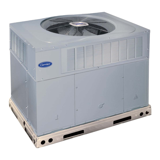
Fig. 1 - Unit 50VT-K
Safety Considerations
Installation and servicing of this equipment can be hazardous due to
mechanical and electrical components. Only trained and qualified
personnel should install, repair, or service this equipment.
Untrained personnel can perform basic maintenance functions such as
cleaning and replacing air filters. All other operations must be performed
by trained service personnel. When working on this equipment, observe
precautions in the literature, on tags, and on labels attached to or shipped
with the unit and other safety precautions that may apply.
Follow all safety codes. Wear safety glasses, protective clothing, and
work gloves. Use quenching cloth for brazing operations. Have a fire
extinguisher available. Read these instructions thoroughly and follow all
warnings or cautions included in literature and attached to the unit.
Consult local building codes, the current editions of the National
Electrical Code (NEC) NFPA 70.
A09033
Advertisement
Table of Contents

Related Manuals for Carrier Comfort 50VT-K


Summary of Contents for Carrier Comfort 50VT-K
-
Page 1: Table Of Contents
50VT-K Comfort™ 13.4 SEER2 Single-Packaged Heat Pump System with Puron® (R-410A) Refrigerant Single Phase 2-5 Nominal Tons (Sizes 24-60) Three Phase 3-5 Nominal Tons (Sizes 36-60) Installation Instruction IMPORTANT: Effective January 1, 2023, all split system and packaged air conditioners must be installed pursuant to applicable regional efficiency standards issued by the Department of Energy. -
Page 2: Introduction
Receiving and Installation In Canada refer to the current editions of the Canadian Electrical Code CSA C22.1. Step 1 – Check Equipment Recognize safety information. This is the safety-alert symbol . When Identify Unit you see this symbol on the unit and in instructions or manuals, be alert to The unit model number and serial number are stamped on the unit the potential for personal injury. - Page 3 50VT-K: Installation Instruction draws air through the outdoor coil and discharges it through the top fan grille. Be sure that the fan discharge does not recirculate to the outdoor coil. Do not locate the unit in either a corner or under an overhead obstruction.
- Page 4 50VT-K: Installation Instruction A221482 Fig. 2 – 24-30 Unit Dimensions Manufacturer reserves the right to change, at any time, specifications and designs without notice and without obligations.
- Page 5 50VT-K: Installation Instruction A221483 Fig. 3 – 36-60 Unit Dimensions Manufacturer reserves the right to change, at any time, specifications and designs without notice and without obligations.
- Page 6 50VT-K: Installation Instruction A180216 Fig. 4 – Roof Curb Dimensions B (small/common B (large UNIT CATALOG base) base) SIZE NUMBER IN. (mm) IN. (mm) IN. (mm) IN. (mm) (mm) IN. (mm) IN. (mm) (mm) (mm) Small or CPRFCURB011B00 14 (356) 10 (254) 32.4 (822) 30.6 (778)
-
Page 7: Inspection
50VT-K: Installation Instruction A09051 RIGGING WEIGHTS (SMALL CABINET) RIGGING WEIGHTS (LARGE CABINET) Unit Unit Rigging Weight 155.6 170.6 Rigging Weight 190.6 199.6 199.6 231.4 NOTE: See dimensional drawing for corner weight distribution. Fig. 5 – Rigging Weights Step 4 – Rig and Place Unit Inspection Prior to initial use, and at monthly intervals, all rigging shackles, clevis WARNING... -
Page 8: Rigging/Lifting Of Unit (See Fig. 5)
50VT-K: Installation Instruction Rigging/Lifting of Unit (See Fig. Configuring Units for Downflow (Vertical) Discharge Lifting holes are provided in base rails as shown. WARNING 1. Attach shackles, clevis pins, and straps to the base rails of the unit. Be sure materials are rated to hold the weight of the unit (See ELECTRICAL SHOCK HAZARD Fig. - Page 9 50VT-K: Installation Instruction 3. Use flexible transition between rigid ductwork and unit to prevent If the installation requires draining the condensate water away from the transmission of vibration. The transition may be screwed or bolted unit, install a field-supplied 2 -in. (51mm) trap at the condensate to duct flanges.
-
Page 10: High-Voltage Connections
50VT-K: Installation Instruction High-Voltage Connections Special Procedures for 208-V Operation The unit must have a separate electrical service with a field-supplied, WARNING waterproof disconnect switch mounted at, or within sight from the unit. Refer to the unit rating plate, NEC and local codes for maximum ELECTRICAL SHOCK HAZARD fuse/circuit breaker size and minimum circuit amps (ampacity) for wire sizing. - Page 11 50VT-K: Installation Instruction c. ELECTRIC HEATING MODE (1.) Thermostat closes circuits R to G, R to Y and R to W/W1 or (1.) Thermostat closes circuit R to W/W1, or W2 and R to G. W2. The compressor, indoor and outdoor fans are There are no on or off delays.
- Page 12 50VT-K: Installation Instruction A09098 Fig. 11 – Typical Installation Manufacturer reserves the right to change, at any time, specifications and designs without notice and without obligations.
- Page 13 50VT-K: Installation Instruction A221468 Fig. 12 – Connection Wiring Schematics 208/230-1-60 Manufacturer reserves the right to change, at any time, specifications and designs without notice and without obligations.
- Page 14 50VT-K: Installation Instruction A221469 Fig. 13 – Ladder Wiring Schematics 208/230-1-60 Manufacturer reserves the right to change, at any time, specifications and designs without notice and without obligations.
- Page 15 50VT-K: Installation Instruction A221470 Fig. 14 – Connection Wiring Schematics - 208/230-3-60 Manufacturer reserves the right to change, at any time, specifications and designs without notice and without obligations.
- Page 16 50VT-K: Installation Instruction A221471 Fig. 15 – Ladder Wiring Schematics - 208/230-3-60 Manufacturer reserves the right to change, at any time, specifications and designs without notice and without obligations.
- Page 17 50VT-K: Installation Instruction A221472 Fig. 16 – Connection Wiring Diagram 460-3-60 Manufacturer reserves the right to change, at any time, specifications and designs without notice and without obligations.
- Page 18 50VT-K: Installation Instruction A221473 Fig. 17 – Ladder Wiring Diagram 460-3-60 Manufacturer reserves the right to change, at any time, specifications and designs without notice and without obligations.
-
Page 19: Pre-Start-Up
50VT-K: Installation Instruction Pre-Start-Up FAN mode is placed in FAN ON position and shuts down when FAN MODE switch is placed in AUTO position. WARNING (2.) Thermostat: When the room temperature rises to a point that is slightly above the cooling control setting of the thermostat, the FIRE, EXPLOSION, ELECTRICAL SHOCK AND thermostat completes the circuit between thermostat ENVIRONMENTAL HAZARD... -
Page 20: Checking And Adjusting Refrigerant Charge
50VT-K: Installation Instruction reversed to correct rotation. When turning backwards, the difference is more than 2°F (1.1°C) lower than required liquid line between compressor suction and discharge pressures may be near zero. temperature. Checking and Adjusting Refrigerant Charge NOTE: If the problem causing the inaccurate readings is a refrigerant leak, refer to Check for Refrigerant Leaks section. -
Page 21: Single Speed Cooling With Higher Electric Heat Speed
50VT-K: Installation Instruction must open the control circuit on humidity rise above the 3. Select speed tap from Table 4 that will achieve required airflow dehumidification set point. from Table 1. Using Fig. 19, move the two pin DEHUM jumper from the “STD” 4. -
Page 22: Demand Defrost Mode
50VT-K: Installation Instruction HIGH R13 C8 AB A15 D5 D3 R3 R5 R6 R W2 Y W3 W3 W2 W2 C SSTZ-8 A09059 Fig. 19 – Interface Fan Board (IFB) C03012 Fig. 20 – Typical Heat Pump Operation, Heating Mode Step 3 –... - Page 23 50VT-K: Installation Instruction Table 4 – Dry Coil Air Delivery* - Horizontal and Downflow Discharge Sizes 24-60 ESP (in. W.C.) Unit Size Motor Speed Blue 0.09 0.07 0.06 Pink Med-Low 0.11 0.12 0.12 0.13 0.13 0.14 0.14 0.15 0.15 0.16 1065 1016 Medium...
- Page 24 50VT-K: Installation Instruction Table 5 – Filter Pressure Drop Table (IN. W.C.) 1200-1800CFM 3.0, 16x24x1+14x24x1 3.5, 0.04 0.05 0.06 0.07 0.08 0.09 0.09 0.10 0.11 0.12 0.12 (406x610x25+356x610x25) 1500-2200CFM 16x24x1+18x24x1 0.04 0.06 0.08 0.10 0.11 0.13 0.14 0.15 (406x610x25+457x610x25) Table 6 – Wet Coil Pressure Drop (IN. W.C.) Unit Standard CFM (SCFM) 1000...
-
Page 25: Maintenance
50VT-K: Installation Instruction Maintenance Indoor Blower and Motor NOTE: All motors are pre-lubricated. Do not attempt to lubricate these To ensure continuing high performance, and to minimize the possibility motors. of premature equipment failure, periodic maintenance must be NOTE: 460 volt units have a stepdown autotransformer that supplies performed on this equipment. - Page 26 50VT-K: Installation Instruction Superheat charging table is derived from optimum performance point. (95_F [35_C] outdoor ambient and (80_F [27_C] dry bulb; 67_F [19_C] wet bulb indoor condition.) Where a dash(--) appears do not attempt to check charge or charge unit under these conditions using the superheat method. (Weigh in method should be used.) A150625 To properly check or adjust charge, conditions must be favorable for subcooling charging.
- Page 27 50VT-K: Installation Instruction Step 2 – Outdoor Coil, Indoor Coil, and Condensate Step 6 – Indoor Airflow Drain Pan The heating and/or cooling airflow does not require checking unless improper performance is suspected. If a problem exists, be sure that all Inspect the condenser coil, evaporator coil, and condensate drain pan at supply-air and return-air grilles are open and free from obstructions, and least once each year.
- Page 28 50VT-K: Installation Instruction specifically designed to operate with Puron (R-410A) systems. R-22 pressure switches must not be used as replacements for the Puron (R-410A) system. FAN GRILLE MOTOR MOTOR SHAFT A08505 MAX DISTANCE BETWEEN TOP OF FAN GRILLE AND BOTTOM OF FAN BLADE “A”...
-
Page 29: Refrigerant
50VT-K: Installation Instruction Refrigerant WARNING PROPERTY HAZARD, PERSONAL INJURY OR ENVIRONMENTAL HAZARD Failure to follow this warning could result in property damage or personal injury or death. This system uses Puron (R-410A) refrigerant which has higher operating pressures than R-22 and other refrigerants. No other refrigerant may be used in this system. -
Page 30: Loss Of Charge Switch
We believe in providing high quality learning experiences both online and in the classroom. Access My Learning Center with your HVACpartners credentials at www.MLCtraining.com. Please contact us at mylearning@carrier.com with questions. Manufacturer reserves the right to change, at any time, specifications and designs without notice and without obligations. - Page 31 50VT-K: Installation Instruction Table 9 – Troubleshooting Chart SYMPTOM CAUSE REMEDY Power failure Call power company Fuse blown or circuit breaker tripped Replace fuse or reset circuit breaker Defective contactor, transformer, or high-pressure, Replace component loss-of-charge or low-pressure switch Compressor and condenser fan will not start. Insufficient line voltage Determine cause and correct Incorrect or faulty wiring...
- Page 32 Access My Learning Center with your HVACpartners credentials at www.mlctraining.com. Please contact us a mylearning@carrier.com with questions. © 2022 Carrier. All rights reserved. Edition Date: 11/15/22 Catalog No: 50VT-19SI Replaces: 50VT-18SI Manufacturer reserves the right to change, at any time, specifications and designs without notice and without obligations.
Need help?
Do you have a question about the Comfort 50VT-K and is the answer not in the manual?
Questions and answers