
Related Manuals for elobau N6


Summary of Contents for elobau N6
- Page 1 Gebrauchsanweisung Version: 1.0 Nr.: 9010052B01D N6/N7 Neigungssensor N6SA, N6SC static N7DA, N7DC dynamic...
- Page 2 Verknüpfungsarten der Relaisausgänge ................19 4.6.2 Schaltverhalten........................21 Verhalten von Ausgangssignalen ................23 4.7.1 Erkennen der Position zur Referenzebene................23 Filter.......................... 23 4.8.1 Tiefpassfilter (N6) ........................24 4.8.2 Sensorfusions-Filter (N7)....................... 24 Montage und Inbetriebnahme Montage........................25 2 / 72 www.elobau.com 9010052B01D...
- Page 3 Einbaulage ....................... 26 Rohdaten ......................... 26 5.3.1 Beschleunigung | Messachsen (N7DC*) ................26 5.3.2 Drehrate | Messachsen (N7DC*)................... 27 Elektrischer Anschluss ..................... 27 5.4.1 Pin-Belegung 1x M12-Stecker (analog)................. 28 5.4.2 Pin-Belegung 1x M12-Stecker (CAN)..................28 5.4.3 Pin-Belegung 2x M12-Stecker (CAN)..................29 5.4.4 Pin-Belegung Deutsch-Stecker (DT06-8S) 8-pol.
- Page 4 Schadensersatz (lt. UWG BGB). Alle Rechte für den Fall der Pa- tenterteilung oder Gebrauchsmustereintragung vorbehalten (DIN34). Gültigkeit Diese Gebrauchsanweisung gilt generell für das auf der Titelseite aufgeführte Produkt N6/ N7 und ist den Produktdokumenten der nachgeschalteten Maschine beizulegen. Weitere Varianten sind möglich und werden bei abweichenden Angaben zusätzlich aufgeführt. Je nach Kundenwunsch oder Sonderausführung können einzelne Bauteile fehlen oder vom...
- Page 5 1. Benutzerinformation Handlungsaufgabe 1. Handlungsschritt: Fordert zum Handeln auf. Zwischenergebnis: Zur Kontrolle eines Handlungsschrittes. 2. Handlungsschritt: Fordert zum Handeln auf. Zwischenergebnis: Zur Kontrolle eines Handlungsschrittes. 3. Handlungsschritt: Fordert zum Handeln auf. Handlungsergebnis Einzelne Handlungsanweisung, ohne chronologische Abfolge werden wie folgt dargestellt: ...
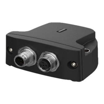
- Page 6 1. Benutzerinformation Funktionsprinzip N6/N7 ist ein kompakter und robuster Neigungssensor, der einfach in Landmaschinen, Baumaschinen und Flurförderzeuge integriert werden kann, um Neigungsinformationen von Maschinenkomponenten zu erfassen und über eine elektrische Schnittstelle bereitzu- stellen. Für den elektrischen Anschluss an ein übergeordnetes System stellt der Neigungssensor auf der Rückseite einen Stecker als elektrische Schnittstelle zur Verfügung.
- Page 7 Defekte, die während dieser Gewährleistungszeit in Form von Material- und/oder Herstel- lungsfehlern auftreten, werden kostenfrei behoben, entweder durch Reparatur oder durch Ersatzlieferung. Es gelten die Allgemeine Lieferbedingungen der elobau GmbH & Co. KG. Bei Erbringung einer Gewährleistung verlängert sich der Gewährleistungszeitraum nicht.
- Page 8 Personals müssen durch den Betreiber genau geregelt sein. Liegen die notwen- digen Kenntnisse bei dem Personal nicht vor, so muss der Betreiber dieses schulen und unterweisen. Dies kann, falls erforderlich, im Auftrag des Betreibers durch den Hersteller oder Lieferer erfolgen. 8 / 72 www.elobau.com 9010052B01D...
- Page 9 3. Transport und Lagerung Konformität Das Produkt N6/N7 entspricht dem Stand der Technik sowie den geltenden Sicherheitsbe- stimmungen zum Zeitpunkt des Inverkehrbringens im Rahmen seiner bestimmungsgemä- ßen Verwendung. Konstruktiv konnte die vorhersehbare Fehlanwendung nicht vermieden werden, ohne die bestimmungsgemäße Funktionalität einzuschränken.
- Page 10 5. Buchse 6. Kennzeichnung Weitere Details entnehmen Sie bitte Ihrem Datenblatt. 4.2.1 Druckausgleichsmembran An der Unterseite des Sensors befindet sich eine Druckausgleichsmembran. Diese ermög- licht den Betrieb des Sensors bei unterschiedlichen Temperaturen und Höhenlagen. Abbildung 2 10 / 72 www.elobau.com 9010052B01D...
- Page 11 4. Produktspezifische Angaben ACHTUNG! Systemfehler durch mechanische Beschädigung! Wird die Druckausgleichsmembran beschädigt, kann es zu einem Systemausfall führen. Membran vor äußeren Einflüssen jeglicher Art zu schützen. Membran nicht überlackieren. Neigungssensor entsprechend positionieren. 4.2.2 Werkstoffdefinition und Materialien Die Materialien des Neigungssensors werden unter Berücksichtigung verschiedener Punk- te ausgewählt, um eine lange Lebensdauer zu gewährleisten.
- Page 12 Gelb Tabelle 2 LED-Status Sensor Ursache Abhilfe CAN Bus Off Error Fehler im CAN-Netzwerk behe- N6/N7 konstant CAN falsche Baudrate eingestellt CAN Baudrate überprüfen Sensor defekt elobau kontaktieren Filter nicht initialisiert Sensor Reset gelb Zu hohe Vibrationen beim Sen-...
- Page 13 4. Produktspezifische Angaben Elektrische Daten Beschreibung N6SA N6SC N7DC N7DA EMV-Konformität entsprechend den gängigen Off-Highway-Normen (Kapitel 2.3 "Konformität") Ideal geeignet für den Einsatz in rauen Umge- bungsbedingungen: • Temperaturbereich: -40…+85 °C • Schutzart: IP67K / IP6K9K • Robustes Gehäuse Großer Versorgungsspannungsbereich 8 VDC...36 VDC Kompakte Bauweise für den Einsatz in engen Einbausituationen...
- Page 14 Abbildung 4 Ausgangssignale Der Neigungssensor N6/N7 verfügt über drei Schnittstellen, über diese er Neigungsinfor- mationen bereitstellen kann. Proportional zum Winkel können über den Analogausgang Ströme bzw. Spannungen ausgegeben werden. Alternativ können die berechneten Winkel auch über CAN versendet werden, wobei die Protokolle CANopen und J1939 zur Verfü- gung stehen.
- Page 15 4. Produktspezifische Angaben 4.5.1 Analoge Ausgangssignale In der folgenden Tabellen ist der Standardsignalbereich abgebildet. Weitere Konfiguratio- nen sind nach Absprache möglich. Ausgangssignal Fehlersignal Weitere technische Angaben finden Sie im 4 mA...20 mA 22 mA jeweils gültigen Datenblatt zu Ihrer Konfigu- 0,5 V...4,5 V ration.
- Page 16 Z-Achse = 0° Z-Achse = 0° Z-Achse = 0° X-Achse = 0° X-Achse = +20° X-Achse = +60° Abbildung 7 CAN: Z = Roll, X = Pitch Messbereich ±60° - vertikale Montage (X/Z-Achse) Abbildung 8 16 / 72 www.elobau.com 9010052B01D...
- Page 17 4. Produktspezifische Angaben Ausgangskennlinien X/Y-Achse Y-Achse = 0° Y-Achse = -20° Y-Achse = -60° X-Achse = 0° X-Achse = 0° X-Achse = 0° Y-Achse = 0° Y-Achse = +20° Y-Achse = +60° X-Achse = 0° X-Achse = 0° X-Achse = 0° Abbildung 9 CAN: Y = Roll, X = Pitch Messbereich ±60°...
- Page 18 = 27,4 V reduziert werden. Abbildung 11 Hinweis Betreiben Sie den Neigungssensor N6/N7 nur innerhalb des zugelassenen Betriebsbe- reich. Bei einem Betrieb außerhalb des zulässigen Betriebsbereich ist eine Funktion nicht mehr gewährleistet und kann den Neigungssensor unter Umständen zerstören. 4.5.2 Anpassung analoger Signale Die analogen Ausgangssignale können unabhängig voneinander für jeden Signalausgang...
- Page 19 4. Produktspezifische Angaben 4.5.3 CAN-Ausgang Alle Informationen zu CAN-Ausgang finden Sie im Kapitel 6. "CANopen | J1939 Schnittstel- le". Relais-Schaltausgänge Die Schaltausgänge bieten eine einfache Möglichkeit, das Überschreiten einer Winkel- schwelle einer angeschlossenen Auswerteeinheit mitzuteilen. Es stehen pro Achse 4 Schaltschwellen zur Verfügung, die den beiden Relais zugewiesen werden können.
- Page 20 Relais 2 = X2/X4 Z2/Z4 Relais 1 = X1/X3 Relais 2 = X2/X4 Relais 1 = X1 Relais 2 = X3 Relais 1 = Z1/Z3 Relais 2 = Z2/Z4 Relais 1 = Z1 Relais 2 = Z3 Tabelle 9 20 / 72 www.elobau.com 9010052B01D...
- Page 21 4. Produktspezifische Angaben Einbaulage horizontale Montage (X/Y-Achse) Abbildung 15 Mögliche Verknüpfungsarten bei horizontaler Montage (X/Y-Achse): Verknüpfungstyp Relaisverknüpfung Relais 1 = X1/X3 Y1/Y3 Relais 2 = - Relais 1 = X1/X3 Relais 2 = Y1/Y3 Relais 1 = X1/X3 Y1/Y3 Relais 2 = X2/X4 Y2/Y4 Relais 1 = X1/X3 Relais 2 = X2/X4 Relais 1 = X1...
- Page 22 Die Neigungsbedingungen einer Achse können ANDe oder ANDd zu den Neigungsbe- dingungen der anderen Achse sein. Beispiel für eine Triggerbedingung, die eine einzige Neigungsbedingung verwendet: Abbildung 17 Beispiel für eine Triggerbedingung, die zwei Neigungsbedingungen ORed verwendet: Abbildung 18 22 / 72 www.elobau.com 9010052B01D...
- Page 23 Nachfolgend ein Beispiel für eine Triggerbedingung, die zwei Neigungsbedingungen jeder Achse verwendet, kombiniert mit einem OR. Das Ergebnis ist ein geschalteter Signalaus- gang, der ausgelöst wird, wenn das N6/N7-Gerät um mehr als 45° in beide Richtungen ge- neigt ist. Abbildung 19...
- Page 24 Raw-Signal (graue Linie) reagiert als das FIR-Filter (grüne Li- nie). Möglich macht dies eine Kombination der nachfolgend beschriebenen Filter. Der N6 Neigungssensor bietet diverse Möglichkeiten das Winkelsignal zu glätten und ro- buster gegen Vibrationen zu machen. Dazu gibt es an zwei Stellen im Signalfluss (Abbil- dung 4) jeweils zwei verschiedene Arten von Filtern, die ausgewählt werden können, ein...
- Page 25 5. Montage und Inbetriebnahme Typische Einsatzszenarien: • Dynamische Anwendungen mobiler Arbeitsmaschinen • Messungen mit geringstmöglichem Zeitverzug im Ausgangssignal • Messungen bei Kurvenfahren • Messungen bei Beschleunigungs- / Bremsvorgängen Montage und Inbetriebnahme Montage ACHTUNG! Gefahr durch unsachgemäßen Einbau! Neigungssensor kann durch übermäßige Stöße und Vibrationen beschädigt werden. Auf das Gehäuse dürfen keine Verwindungskräfte oder sonstige mechanische Belastungen einwirken.
- Page 26 Neigungssensoren nur dann als Huckepack montieren, wenn Abstandshalter zwischen beiden Neigungssensoren verwendet werden! Einbaulage Die Neigungssensoren N6/N7 können passend zur Anwendung flexibel an der Maschine platziert werden. Dabei müssen jedoch die Aspekte unter Kapitel 7.2 "Einflussfaktoren Per- formance", Seite 52 berücksichtigt werden.
- Page 27 Personen- oder Sachschäden folgen können. Elektrische Daten aus dem jeweiligen Datenblatt entnehmen und einhalten. Signalverlauf des Ausgangssignals ist auf dem Datenblatt abgebildet oder wird auf Nachfrage von elobau zur Verfügung gestellt. Temperatur-Drift beachten. Neigungssensor anschließen 1. Spannungsfreien Zustand aller Zuleitungen prüfen.
- Page 28 Pin-Belegung 1x M12-Stecker (CAN) In der Variante mit CAN-Signalausgang kann das System mit einem M12-Stecker mit 5 Pins ausgestattet werden (Abbildung 26). Belegung Beschreibung n.c. not connected Betriebsspannung Masse CAN_H Signalleitung CAN CAN_L Signalleitung CAN Tabelle 14 28 / 72 www.elobau.com 9010052B01D...
- Page 29 5. Montage und Inbetriebnahme 5.4.3 Pin-Belegung 2x M12-Stecker (CAN) In der Variante mit CAN-Signalausgang kann das System mit zwei M12-Steckern mit je 5 Pins ausgestattet werden (Abbildung 26). Diese Zuordnung ist abwärtskompatibel zu be- stehenden elobau Neigungssensoren. Belegung Beschreibung n.c. not connected...
- Page 30 Der Sensor bestätigt das Setzen des Nullpunkts durch einen Neustart. Die aktuelle Position wurde als Nullpunkt erfolgreich berücksichtigt. Variante mit J1939-Signalausgang – N6SC* | N7DC* Für eine Nullpunktjustierung über CAN sind entsprechende UDS-Protokolle erforderlich. Siehe nachfolgende Vorgehensweise. 30 / 72 www.elobau.com 9010052B01D...
- Page 31 5. Montage und Inbetriebnahme Nullpunkt per UDS justieren 1. Extended Diagnostic Session (0x3) 2. Seed & Key 3. Start Routine S31 0x0103 4. Hard Reset (S11 0x1) Die Winkelausgabe liefert den Wert „0“. Nullpunkt per UDS justiert. Nullpunkt per CANopen justieren 1.
- Page 32 Tabelle 21 Hinweis N6 Um mit dem N6 das Verhalten des N5 bei Überschreitung 1:1 nachzustellen, kann die Feh- lerreaktion auf „no reaction“ geändert werden. Dabei wird der aktuelle Winkel auch wäh- rend der Überschreitung berechnet. Diese Vorgehensweise wird jedoch nicht empfohlen.
- Page 33 5. Montage und Inbetriebnahme Signal SafeState (No Healing) (1) J1939 DM1 Nachricht wird bei der Überschreitung des Messbereichs gesetzt. Die „Figure Of Me- rit“ in den CAN-Botschaften SSI, SSI2, ACCS, ARI und ePSSI1 wird auf „degraded“ ge- setzt. Der Sensor muss neu gestartet werden, um den Fehler als inaktiv zu markieren. CANopen Es wird eine EMCY-Nachricht gesendet.
- Page 34 32 (default) Tabelle 22 Bus-Abschlusswiderstand Information An den Enden des Netzwerks muss ein Abschlusswiderstand vorhanden sein. Der elobau Neigungssensor besitzt keinen internen Abschlusswiderstand. Einstellungsmöglichkeiten der Tiefpassfilter (FIR-Filter) Die Filtereinheit beinhaltet einen Mittelwert- oder einen Vibrationsfilter (FIR-Filter), die auf die Rohdaten und auf die Winkelsignale angewandt werden können.
- Page 35 6. CANopen | J1939 Schnittstelle Rohdaten- und Winkelfilterung Filterlänge MAVG Filterprofil Filterlänge, Grenzfrequenz Abbildung 27 CANopen Index Sub- Beschreibung Default Unit 0x... 0x... index Rohdaten Tiefpassfilter F215 2001 Filterprofil 0: Tiefpassfilter mit Blackman- Harris-Fenster 1: Gleitender Mittelwertfilter F214 2001 Filterlänge 2,5 ms 1024 F213 2001...
- Page 36 Seite 55 und in Kapitel 9.2 "Parameterkonfiguration CANopen", Seite 60. 6.2.2 Vibrationsfilter In den Neigungssensoren N6 und N7 ist ein digitales Tiefpassfilter (FIR-Filter) implemen- tiert, bei dem die Filterordnung sowie die Grenzfrequenz einstellbar sind. Mit den Objekten 0xF210 bzw. F213 (cut-off frequency) kann in 0,001 Hz-Schritten die Grenzfrequenz zwischen 1 Hz und 25 Hz eingestellt werden.
- Page 37 6. CANopen | J1939 Schnittstelle 1. Rohsignal 3. mittlere Filterung 2. leichte Filterung 4. starke Filterung Abbildung 28: Rauschsignal mit unterschiedlichen Filtereinstellungen 13.02.24 V1.0 37 / 72...
- Page 38 In Abbildung 30 ist der Frequenzgang des FIR-Filters dargestellt, beispielhaft mit einer Grenzfrequenz von 5 Hz und unterschiedlichen Filterlängen. Es wird ersichtlich, dass mit zunehmender Filterlänge die Filtersteilheit zunimmt. Eine höhere Filterlänge führt jedoch auch zu einer höheren Verzögerung (Gruppenlaufzeit) des Signals.: 38 / 72 www.elobau.com 9010052B01D...
- Page 39 6. CANopen | J1939 Schnittstelle 1. fcutoff = 5 Hz / FIR-Filter (FIR) = 250 2. fcutoff = 5 Hz / FIR-Filter (FIR) = 128 3. fcutoff = 5 Hz / FIR-Filter (FIR) = 64 4. fcutoff = 5 Hz / FIR-Filter (FIR) = 32 5.
- Page 40 6. CANopen | J1939 Schnittstelle Relaisschaltpunkte Der Neigungssensor N6/N7 ist mit bis zu 2 Relais-Ausgängen erhältlich. Mit Hilfe unter- schiedlicher Verknüpfungsarten können bis zu 4 Schaltpunkte den zwei Ausgängen zuge- ordnet werden. Für jeden dieser Schaltpunkte kann eine Ein- und Ausschaltverzögerungs- zeit sowie eine Hysterese definiert werden.
- Page 41 6. CANopen | J1939 Schnittstelle TPDO #1 In der TPDO #1 werden die Rohdaten des Beschleunigungssensors in [g] übertragen. Die Daten werden unter der Message-ID 0x280 + Node ID gesendet. Die Nachricht kann im Ob- jekt-Verzeichnis unter der Message-ID 0x1801.5 aktiviert werden. Byte Accelerati Accelerati...
- Page 42 Proprietary Slope Sensor Information SSI2 Slope Sensor Information 2 ACCS Acceleration Status Angular Rate Information ePSSI1 elobau Proprietary Slope Sensor Information 1 ePSSI5 elobau Proprietary Slope Sensor Information 5 Tabelle 35: Table Proprietary CAN messages 42 / 72 www.elobau.com 9010052B01D...
- Page 43 6. CANopen | J1939 Schnittstelle 6.4.6 Detailed message definition Dient zur Übertragung von Informationen über die berechneten Neigungssensorinformati- onen. Liefert den Neigungs- und Rollwinkel in einem Bereich von -64° und 64,51°. Die Auf- lösung des Winkels ist auf 16-Bit eingestellt. Message parameter Parameter Definition...
- Page 44 100 Hz. Doesn't account for delay introduced by low pass filters. Tabelle 39: Table SSI2 Message Layout elobau Proprietary Slope Sensor Information 1 Die elobau Proprietary Slope Sensor Information Nachricht liefert: • den Neigungswinkel, • den Rollwinkel in erweitertem Format, •...
- Page 45 Message type Proprietary B User defined PGN in range 0xFF00 – 0xFFFF Parameter Group 0xFF2A elobau Proprietary Slope Sensor Information 1. Number (PGN) Tabelle 40: Table elobau Proprietary Slope Sensor Information 1 Message layout Signal Description Unit Size Pitch Angle Extended Range -...
- Page 46 Message type Proprietary B User defined PGN in range 0xFF00 – 0xFFFF. Parameter Group 0xFF2B elobau Proprietary Slope Sensor Information 2. Number (PGN) Tabelle 42: Table elobau Proprietary Slope Sensor Information 2 Message layout Signal Size Acceleration X 5347 16 bits...
- Page 47 Figure of Merit - Y 4987 2 bits Figure of Merit - Z 4988 2 bits Tabelle 45: Table elobau Proprietary Slope Sensor Information 3 elobau Proprietary Slope Sensor Information 5 Gibt die Orientierung in Quaternion-Notation an. Message parameter Parameter Definition...
- Page 48 Positive Acknowledgment (ACK), if the request was successful. Negative Acknowledgment (NACK), if the requested PGN does not exist/ is not implemented. Access Denied, not used. Cannot Respond, BAM protocol is busy. Tabelle 50: Table Acknowledgement control bytes 48 / 72 www.elobau.com 9010052B01D...
- Page 49 6. CANopen | J1939 Schnittstelle Requestable PGN definition J1939 Soft PGN Byte Description 4 (Number of software identification designators represented in the software identification parameter group) 1...15 Customer SOFT-ID 0 Field delimiter (*) 17...31 Customer SOFT-ID 1 Field delimiter (*) 33...47 Software Version Number (example „001.000.000.000“) Field delimiter (*)
- Page 50 10: reserved 11: Unavailable / 00 Not Flash DTC1 Error Code - optional DTC2 Error Code - optional DTC3 Error Code - optional 112 32 DTC4 Error Code - optional Tabelle 53 J1939 DM1 / DM2 50 / 72 www.elobau.com 9010052B01D...
- Page 51 6. CANopen | J1939 Schnittstelle Diagnostic Trouble Codes (DTCs) Customer ID Description Resulting system state special instruction spn_generic_sw_error General SW error 522000 12 system_safe_state replace frimware/ sensor spn_can_busoff_detec- CAN bus off detec- 522001 2 temporary condition, check the can bus wiring + configuration spn_cpu_temperatu- CPU Temperature...
- Page 52 Vibrationen Bei bestimmten Anwendungen mit starken Vibrationen oder langen Kurvenfahren können die integrierten Sensoren Störungen verursachen. Dabei werden diese Störungen vom N6/ N7 als Winkeländerungen erfasst und können sich je nach Anwendung negativ auf den Be- trieb des Neigungssensors auswirken.
- Page 53 Der Neigungssensor ist wartungsfrei. VORSICHT! Gefahr durch Öffnen des Neigungssensors. Ein Öffnen des N6/N7 führt zu Gewährleistungs- und Haftungsausschluss. Weiterhin kön- nen Fehlfunktionen der Maschine zu Personen- oder Sachschäden führen. Neigungssensor nicht öffnen. Elektronik oder Mechanik nicht verändern.
- Page 54 Das Symbol bedeutet, dass ein Produkt nach Richtlinie 2012/ 19/EU getrennt von anderen Abfällen gesammelt werden muss, wenn es das Ende seiner Nutzungsdauer erreicht. Für weitere Informationen wenden Sie sich bitte an elobau oder an Ihren Händler vor Ort. Verpackung und verbrauchte Teile gemäß den jeweiligen Lan- desvorschriften entsorgen.
- Page 55 9. Anhang Anhang Parameterkonfiguration J1939 J1939 Parameter Description Default Unit Index Sub- 0x... 0x... index F202 inc_plane Mounting position of the Configuration 2000 sensor (horizontal, verti- Index cal) F203 inc_offset_yaw Add an offset to the pitch -60000 60000 0,001° 2000 angle F204 inc_offset_roll Add an offset to the roll...
- Page 56 Compare function to use 0 0 = none 200A put_0_axis_0_con 1 = less than d_1_cmp 2 = greater than F25B swed_out- Input signal to use to 0 = yaw 200A put_0_axis_1_ang compare axis 1 = pitch 2 = roll 56 / 72 www.elobau.com 9010052B01D...
- Page 57 9. Anhang J1939 Parameter Description Default Unit Index Sub- 0x... 0x... index F25C swed_out- Overall logic operation to 0 = only single 200A put_0_axis_1_lo- compare operators of operator gic_link axis 0 1 = AND 2 = OR F25D swed_out- Threshold angle that trig- 180000 0,001°...
- Page 58 Number of attempts to 0x7FF 5001 re_attempts reset a detected bus off FFFFF state (within on drive cycle) before stay in bus off state F293 can_busoff_resto- Time betweeen to CAN 1000 3000 re_timeout bus reset events 58 / 72 www.elobau.com 9010052B01D...
- Page 59 Time of fault free CAN 300000 0 100000 3000 crement_time bus which leads to a decrementing of the error counter F295 can_s27_ext_key Please contact elobau, if 0x8000 0x7FF your application requires 0000 FFFFF your own Seed&Key F296 can_s27_prog_ke Please contact elobau, if...
- Page 60 (objects with marking PARA) to factory settings. U32 (read COB-ID EMCY 0x80+N 1014 only) ode-ID Producer Heartbeat 0 = not used 1017 Time - PARA (Unit 1 ms) Identity Object (read Number of Entries 1018 only) 60 / 72 www.elobau.com 9010052B01D...
- Page 61 9. Anhang CANopen Typ Parame- Description Default Unit Index Sub- 0x... 0x... index U32 (read Vendor ID 0x0000 elobau Vendor ID: 1018 only) 00B4 0x000000B4 U32 (read Product Code 0x0000 1018 only) 0301 U32 (read Revision Number 0x0000 1018 only)
- Page 62 1 = pitch s_0_angle 2 = roll F256 I32 swed_out- Overall logic operation to 0 = only single ope- 200A 0x6 put_0_axi compare operators of rator s_0_lo- axis 0 1 = AND gic_link 2 = OR 62 / 72 www.elobau.com 9010052B01D...
- Page 63 9. Anhang CANopen Typ Parame- Description Default Unit Index Sub- 0x... 0x... index F257 I32 swed_out- Threshold angle that trig- 180000 0,001° 200A 0x7 put_0_axi gers compare function 180000 s_0_cond _0_angle F258 I32 swed_out- Compare function to use 0 0 = none 200A 0x8 put_0_axi 1 = less than...
- Page 64 1 = pitch s_1_angle 2 = roll F27C I32 swed_out- Overall logic operation to 0 = only single ope- 200B 0xC put_1_axi compare operators of rator s_1_lo- axis 0 1 = AND gic_link 2 = OR 64 / 72 www.elobau.com 9010052B01D...
- Page 65 9. Anhang CANopen Typ Parame- Description Default Unit Index Sub- 0x... 0x... index F27D I32 swed_out- Threshold angle that trig- 180000 0,001° 200B 0xD put_1_axi gers compare function 180000 s_1_cond _0_angle F27E I32 swed_out- Compare function to use 0 0 = none 200B 0xE put_1_axi 1 = less than...
- Page 66 0xFE or 0xFF. This value limits the transmission rate of the TPDOs even if the event time is set to a smaller time or the map- ped objects change fas- ter than the inhibit time 66 / 72 www.elobau.com 9010052B01D...
- Page 67 9. Anhang CANopen Typ Parame- Description Default Unit Index Sub- 0x... 0x... index F2E6 I32 co_tpdo1c The time is the maximum 0xFFFF ms 1800 om_event interval for PDO trans- timer mission if the transmis- sion type is set to 0xFE F2E7 I32 co_tpdo1 object 0x6010.00 (X-...
- Page 68 0xFE or 0xFF. This value limits the transmission rate of the TPDOs even if the event time is set to a smaller time or the map- ped objects change fas- ter than the inhibit time 68 / 72 www.elobau.com 9010052B01D...
- Page 69 9. Anhang CANopen Typ Parame- Description Default Unit Index Sub- 0x... 0x... index F2F8 I32 co_tpdo2c The time is the maximum 0xFFFF ms 1801 om_event interval for PDO trans- timer mission if the transmis- sion type is set to 0xFE F2F9 I32 co_tpdo3c COBID used...
- Page 70 1 = Enables and the NC contact of the relay is closed. of the relay is clo- sed. If the inversion is deactivated, the NC contact opens when the switching points are exceeded. 70 / 72 www.elobau.com 9010052B01D...
- Page 71 9. Anhang Switch Description Unit 0x... output F270 2 Activate switching output 0 = Switched off 1 = Switched on F271 2 Hysterese 0,001° F272 2 Switch-on delay measuring axis 1 F283 2 Switch-on delay measuring axis 2 F273 2 Switch-off delay measuring axis 1 F284 2 Switch-off delay measuring axis 2...
- Page 72 GmbH & Co. KG Zeppelinstraße 44 D-88299 Leutkirch +49-7561-970-0 www.elobau.com info@elobau.com © 2024 by elobau...
- Page 73 Instruction manual Version: 1.0 No.: 9010052B01D N6/N7 Tilt sensor N6SA, N6SC static N7DA, N7DC dynamic...
-
Page 74: Table Of Contents
Behaviour of output signals ..................23 4.7.1 Detection of the position in relation to the reference plane ........... 23 Filter.......................... 23 4.8.1 Low-pass filter (N6) ....................... 24 4.8.2 Sensor fusion filter (N7)......................24 Installation and putting into service Installation......................... 25 2 / 72 www.elobau.com... - Page 75 Mounting position ..................... 26 Raw data ........................26 5.3.1 Acceleration | Measurement axes (N7DC*)................26 5.3.2 Rotation rate | Measurement axes (N7DC*)................27 Electrical connection ....................27 5.4.1 Pin-assignment 1x M12 connector (analogue) ..............28 5.4.2 PIN assignment 1x M12 connector (CAN)................28 5.4.3 PIN assignment 2x M12 connector (CAN)................
-
Page 76: User Information
(as per UWG BGB). All rights reserved in the event of patent or utility model (DIN34). Validity This Instruction manual generally applies to the product N6/N7 listed on the title page and must be appended to the product documents of the downstream machine. Other variants are possible and are also listed in case of deviating specifications. -
Page 77: Abbreviations Used
1. User information Action task 1. Action step: Prompts an action. Interim result: To check an action step. 2. Action step: Prompts an action. Interim result: To check an action step. 3. Action step: Prompts an action. Result of action Individual handling instructions, without a chronological order, are represented as follows: ... -
Page 78: Functional Principle
1. User information Functional principle N6/N7 is a compact and robust tilt sensor that can be easily integrated into agricultural ma- chinery, construction machinery and industrial trucks to record tilt information from machine components and make it available via an electrical interface. -
Page 79: Warranty And Liability
Defects in the form of material or manufacturing defects that occur during this warranty pe- riod shall be rectified free of charge either by repair or replacement. The General Terms and Conditions of Delivery of elobau GmbH & Co. KG apply. If a warranty is provided, the warranty period is not extended. -
Page 80: Safety Instructions
If personnel do not possess the requisite knowledge, the operator must provide training and instruction. If necessary, this can be provided by the manufacturer or supplier on behalf of the operator. 8 / 72 www.elobau.com 9010052B01D... -
Page 81: Conformity
3. Transport and storage Conformity The product N6/N7 conforms to the state of the art plus the applicable safety conditions at the time of bringing into circulation within the scope of its intended use. From a design point of view, foreseeable misuse cannot be avoided without limiting the intended functionality. -
Page 82: Dimensions
Please refer to your data sheet for further details. 4.2.1 Pressure equalisation membrane There is a pressure equalisation membrane on the underside of the sensor. This enables the sensor to operate at different temperatures and altitudes. Figure 2 10 / 72 www.elobau.com 9010052B01D... -
Page 83: Material Definition And Materials
4. Product-specific information ACHTUNG! System error due to mechanical damage! If the pressure equalisation membrane is damaged, this can lead to a system failure. Protect the membrane from external influences of any kind. Do not paint over the membrane. ... -
Page 84: Integrated Led Configuration
Yellow Table 2 LED status Sensor Cause Remedy CAN Bus Off Error Rectify error in CAN network N6/N7 CAN has incorrect baud rate set Check CAN baud rate constant Sensor defective Contact elobau Filter not initialised Sensor reset Yellow Too much vibration when sensor... -
Page 85: Electrical Data
4. Product-specific information Electrical data Description N6SA N6SC N7DC N7DA EMC conformity in accordance with the current off-highway standards (chapter 2.3 "Conformity") Ideally suited for use in harsh environmental con- ditions: • Temperature range: -40 - +85 °C • Protection type: IP67K / IP6K9K •... -
Page 86: Signal Flow
Figure 4 Output signals The tilt sensor N6/N7 has three interfaces via which it can provide tilt information. Currents or voltages can be output via the analogue output in proportion to the angle. Alternatively, the calculated angles can also be sent via CAN, whereby the CANopen and J1939 proto- cols are available. -
Page 87: Analogue Output Signals
4. Product-specific information 4.5.1 Analogue output signals The standard signal range is shown in the following tables. Other configurations are possi- ble on request. Output signal Error signal Further technical details can be found in the 4 mA - 20 mA 22 mA relevant data sheet for your configuration. - Page 88 Z-axis = 0° Z-axis = 0° Z-axis = 0° X-axis = 0° X-axis = +20° X-axis = +60° Figure 7 CAN: Z = Roll, X = Pitch Measuring range ±60° - vertical mounting (X/Z-axis) Figure 8 16 / 72 www.elobau.com 9010052B01D...
- Page 89 4. Product-specific information X/Y-axis output characteristics Y-axis = 0° Y-axis = -20° Y-axis = -60° X-axis = 0° X-axis = 0° X-axis = 0° Y-axis = 0° Y-axis = +20° Y-axis = +60° X-axis = 0° X-axis = 0° X-axis = 0° Figure 9 CAN: Y = Roll, X = Pitch Measuring range ±60°...
-
Page 90: Adaptation Of Analogue Signals
= 27.4 V. Figure 11 Note Only operate the tilt sensor N6/N7 within the permissible operating range. If operated out- side the permissible operating range, a function is no longer guaranteed and can destroy the tilt sensor under certain circumstances. -
Page 91: Can Output
4. Product-specific information 4.5.3 CAN output All information on CAN output can be found at chapter 6. "CANopen | J1939 interface". Relay switching outputs The switching outputs offer a simple option of communicating the exceeding of an angle threshold of a connected evaluation unit. 4 switching thresholds per axis are available which can be assigned to the two relays. - Page 92 Relay 2 = X2/X4 Z2/Z4 Relay 1 = X1/X3 Relay 2 = X2/X4 Relay 1 = X1 Relay 2 = X3 Relay 1 = Z1/Z3 Relay 2 = Z2/Z4 Relay 1 = Z1 Relay 2 = Z3 Table 9 20 / 72 www.elobau.com 9010052B01D...
-
Page 93: Switching Behaviour
4. Product-specific information Installation position horizontal mounting (X/Y-axis) Figure 15 Possible linking types for horizontal mounting (X/Y-axis): Linking type Relay linking Relay 1 = X1/X3 Y1/Y3 Relay 2 = - Relay 1 = X1/X3 Relay 2 = Y1/Y3 Relay 1 = X1/X3 Y1/Y3 Relay 2 = X2/X4 Y2/Y4 Relay 1 = X1/X3 Relay 2 = X2/X4... - Page 94 The tilt conditions of one axis can be ANDed or ORed with the tilt conditions of the other axis. Example of a trigger condition that uses a single tilt condition: Figure 17 Example of a trigger condition that uses two ORed tilt conditions: Figure 18 22 / 72 www.elobau.com 9010052B01D...
-
Page 95: Behaviour Of Output Signals
Below is an example of a trigger condition that uses two tilt conditions of each axis, combi- ned with an OR. The result is a switched signal output that is triggered when the N6/N7de- vice is tilted by more than 45° in either direction. -
Page 96: Low-Pass Filter (N6)
The N6 tilt sensor offers various options for smoothing the angle signal and making it more robust against vibrations. There are two different types of filter that can be selected at two points in the signal flow (Figure 4): a mid-pass filter or a low-pass filter. -
Page 97: Installation And Putting Into Service
5. Installation and putting into service Typical application scenarios: • Dynamic applications in mobile machinery • Measurements with the smallest possible time delay in the output signal • Measurements when cornering • Measurements during acceleration/braking processes Installation and putting into service Installation ACHTUNG! Danger due to incorrect installation! -
Page 98: Mounting Position
Only mount tilt sensors as a piggyback if spacers are used between the two tilt sen- sors! Mounting position The tilt sensors N6/N7 can be placed on the machine flexibly to suit the application. Howe-ver, the aspects under chapter 7.2 "Performance-Influencing factors", page 52 must be ta-ken into consideration. -
Page 99: Rotation Rate | Measurement Axes (N7Dc*)
Please find and comply with the electrical data in the respective data sheet. Signal path of the output signal is depicted on the data sheet or is made available by elobau on request. Please pay attention to temperature drift. -
Page 100: Pin-Assignment 1X M12 Connector (Analogue)
In the variant with CAN signal output, the system can be equipped with a M12 connector with 5 pins (Figure 26). Connection Description n.c. not connected Operating voltage Ground CAN_H CAN signal line CAN_L CAN signal line Table 14 28 / 72 www.elobau.com 9010052B01D... -
Page 101: Pin Assignment 2X M12 Connector (Can)
5.4.3 PIN assignment 2x M12 connector (CAN) In the variant with CAN signal output, the system can be equipped with two M12 connector, each with 5 pins (Figure 26). This assignment is backwards compatible with existing elobau tilt sensors. Connection Description n.c. -
Page 102: Offset Correction
The current position was successfully taken into account as the zero point. Variant with J1939 signal output - N6SC* | N7DC* Appropriate UDS protocols are required for zero point adjustment via CAN. See the proce- dure below. 30 / 72 www.elobau.com 9010052B01D... -
Page 103: Offset Setting
5. Installation and putting into service Adjusting the zero point via UDS 1. Extended Diagnostic Session (0x3) 2. Seed & Key 3. Start routine S31 0x0103 4. Hard reset (S11 0x1) The angle output returns the value "0". Zero point adjusted via UDS. Adjusting the zero point via CANopen 1. -
Page 104: Sensor Behaviour When Measuring Range Exceeded
Table 21 Note N6 In order to readjust the behaviour of the N5 with the N6 when exceeding 1:1, the error res- ponse can be changed to “no reaction”. The current angle is also calculated during the ex- cess. This procedure, however, is not recommended. -
Page 105: Putting Into Service
5. Installation and putting into service Signal SafeState (No Healing) (1) J1939 DM1 message is set if the measuring range is exceeded. The “figure of merit” in the CAN messages SSI, SSI2, ACCS, ARI and ePSSI1 is set to “degraded”. The sensor must be res- tarted in order to mark the error as inactive. -
Page 106: Canopen | J1939 Interface
Table 22 Bus terminating resistor Information A terminating resistor must be present on the end of the network. The elobau tilt sensor does not have an internal terminating resistor. Low-pass filter configuration options (FIR filter) The filter unit contains an average value filter or a vibration filter (FIR filter), which can be applied to the raw data and to the angle signals. - Page 107 6. CANopen | J1939 interface Raw data and angle filtering Filter length MAVG Filter profile Filter length, Cut-off frequency Figure 27 CANopen Index Sub- Description Default Min. Max. Unit 0x... 0x... index Low-pass filter raw data F215 2001 Filter profile 0: Low-pass fil- ter with Black- man-Harris...
-
Page 108: Average Value Filter
6.2.2 Vibration filter A digital low pass filter (FIR filter) is implemented in the N6 and N7 tilt sensors, in which the filter order and the limit frequency can be set. With the objects 0xF210 or F213 (cut-off frequency), the cut-off frequency can be set bet- ween 1 Hz and 25 Hz in steps of 0.001 Hz. - Page 109 6. CANopen | J1939 interface 1. Raw signal 3. Medium filtering 2. Low filtering 4. Strong filtering Figure 28: Noise signal with different filter settings 13.02.24 V1.0 37 / 72...
- Page 110 5 Hz and different filter lengths. It can be seen that the filter slope increases with increasing filter length. However, a higher filter length also results in a greater delay (group delay) of the signal: 38 / 72 www.elobau.com 9010052B01D...
- Page 111 6. CANopen | J1939 interface 1. fcutoff = 5 Hz / FIR filter (FIR) = 250 2. fcutoff = 5 Hz / FIR filter (FIR) = 128 3. fcutoff = 5 Hz / FIR filter (FIR) = 64 4. fcutoff = 5 Hz / FIR filter (FIR) = 32 5.
-
Page 112: Relay Switching Points
6. CANopen | J1939 interface Relay switching points The tilt sensor N6/N7 is available with up to 2 relay outputs. Up to 4 switching points can be assigned to the two outputs with the aid of different connection types. A switch-on and switch-off delay time can be defined for each of these switching points as well as a hyste- resis. - Page 113 6. CANopen | J1939 interface TPDO #1 In TPDO #1, the raw data of the acceleration sensor is transmitted in [g]. The data is sent under the message ID 0x280 + Node ID. The message can be activated in the object direc- tory under the message ID 0x1801.5.
-
Page 114: Canopen Error Codes
Proprietary Slope Sensor Information SSI2 Slope Sensor Information 2 ACCS Acceleration Status Angular Rate Information ePSSI1 elobau Proprietary Slope Sensor Information 1 ePSSI5 elobau Proprietary Slope Sensor Information 5 Table 35: Table Proprietary CAN messages 42 / 72 www.elobau.com 9010052B01D... -
Page 115: Detailed Message Definition
6. CANopen | J1939 interface 6.4.6 Detailed message definition Used to transmit information about the calculated tilt sensor information. Provides the tilt and roll angle in a range of -64° and 64.51°. The resolution of the angle is set to 16-bit. Message parameter Parameter Definition... - Page 116 Doesn't account for delay introduced by low pass filters. Table 39: Table SSI2 Message Layout elobau Proprietary Slope Sensor Information 1 The elobau Proprietary Slope Sensor Information message provides: • Angle of tilt, • Roll angle in an extended format, •...
- Page 117 Message type Proprietary B User defined PGN in range 0xFF00 – 0xFFFF Parameter Group 0xFF2A elobau Proprietary Slope Sensor Information 1. Number (PGN) Table 40: Table elobau Proprietary Slope Sensor Information 1 Message layout Signal Description Unit Size Pitch Angle Extended Range -...
- Page 118 Message type Proprietary B User defined PGN in range 0xFF00 – 0xFFFF. Parameter Group 0xFF2B elobau Proprietary Slope Sensor Information 2. Number (PGN) Table 42: Table elobau Proprietary Slope Sensor Information 2 Message layout Signal Size Acceleration X 5347 16 bits...
-
Page 119: Definition Of J1939 Request Pgn
Figure of Merit - Y 4987 2 bits Figure of Merit - Z 4988 2 bits Table 45: Table elobau Proprietary Slope Sensor Information 3 elobau Proprietary Slope Sensor Information 5 Indicates the orientation in quaternion notation. Message parameter Parameter Definition... - Page 120 Positive Acknowledgment (ACK), if the request was successful. Negative Acknowledgment (NACK), if the requested PGN does not exist/ is not implemented. Access Denied, not used. Cannot Respond, BAM protocol is busy. Table 50: Table Acknowledgement control bytes 48 / 72 www.elobau.com 9010052B01D...
- Page 121 6. CANopen | J1939 interface Requestable PGN definition J1939 Soft PGN Byte Description 4 (Number of software identification designators represented in the software identification parameter group) 1...15 Customer SOFT-ID 0 Field delimiter (*) 17...31 Customer SOFT-ID 1 Field delimiter (*) 33...47 Software Version Number (example „001.000.000.000“) Field delimiter (*)
- Page 122 10: reserved 11: Unavailable / 00 Not Flash DTC1 Error Code - optional DTC2 Error Code - optional DTC3 Error Code - optional 112 32 DTC4 Error Code - optional Table 53 J1939 DM1 / DM2 50 / 72 www.elobau.com 9010052B01D...
-
Page 123: Diagnostic Trouble Codes (Dtcs)
6. CANopen | J1939 interface Diagnostic Trouble Codes (DTCs) Customer ID Description Resulting system state special instruction spn_generic_sw_error General SW error 522000 12 system_safe_state replace frimware/ sensor spn_can_busoff_detec- CAN bus off detec- 522001 2 temporary condition, check the can bus wiring + configuration spn_cpu_temperatu- CPU Temperature... -
Page 124: Operation
The tilt sensor is subject to stringent quality control. It is extensively tested before despatch and calibrated and adjusted for the desired end application. Performance-Influencing factors The N6/N7 uses acceleration sensors to calculate changes in direction. Some factors can influence operation. Vibrations In certain applications with strong vibrations or long cornering, the integrated sensors can cause interference. -
Page 125: Error Messages, Troubleshooting
The tilt sensor is maintenance-free. VORSICHT! Danger due to opening the tilt sensor. Opening the N6/N7 results in voiding of warranty and exclusion of liability. Furthermore, machinery malfunctions can lead to personal injury or damage to property. Do not open the tilt sensor. -
Page 126: Dismantling
Dispose of packaging and used parts in accordance with the relevant national regulations. N6/N7 Do not dispose of with do- mestic waste; e. g. dispose of at the collection centre of a was- te management utility. -
Page 127: Appendix
9. Appendix Appendix Parameter configuration J1939 J1939 Parameter Description Default Unit Index Sub- 0x... 0x... index F202 inc_plane Mounting position of the Configuration 2000 sensor (horizontal, verti- Index cal) F203 inc_offset_yaw Add an offset to the pitch -60000 60000 0,001° 2000 angle F204 inc_offset_roll... - Page 128 Compare function to use 0 0 = none 200A put_0_axis_0_con 1 = less than d_1_cmp 2 = greater than F25B swed_out- Input signal to use to 0 = yaw 200A put_0_axis_1_ang compare axis 1 = pitch 2 = roll 56 / 72 www.elobau.com 9010052B01D...
- Page 129 9. Appendix J1939 Parameter Description Default Unit Index Sub- 0x... 0x... index F25C swed_out- Overall logic operation to 0 = only single 200A put_0_axis_1_lo- compare operators of operator gic_link axis 0 1 = AND 2 = OR F25D swed_out- Threshold angle that trig- 180000 0,001°...
- Page 130 Number of attempts to 0x7FF 5001 re_attempts reset a detected bus off FFFFF state (within on drive cycle) before stay in bus off state F293 can_busoff_resto- Time betweeen to CAN 1000 3000 re_timeout bus reset events 58 / 72 www.elobau.com 9010052B01D...
- Page 131 Time of fault free CAN 300000 0 100000 3000 crement_time bus which leads to a decrementing of the error counter F295 can_s27_ext_key Please contact elobau, if 0x8000 0x7FF your application requires 0000 FFFFF your own Seed&Key F296 can_s27_prog_ke Please contact elobau, if...
-
Page 132: Parameter Configuration Canopen
(objects with marking PARA) to factory settings. U32 (read COB-ID EMCY 0x80+N 1014 only) ode-ID Producer Heartbeat 0 = not used 1017 Time - PARA (Unit 1 ms) Identity Object (read Number of Entries 1018 only) 60 / 72 www.elobau.com 9010052B01D... - Page 133 9. Appendix CANopen Typ Parame- Description Default Unit Index Sub- 0x... 0x... index U32 (read Vendor ID 0x0000 elobau Vendor ID: 1018 only) 00B4 0x000000B4 U32 (read Product Code 0x0000 1018 only) 0301 U32 (read Revision Number 0x0000 1018 only)
- Page 134 1 = pitch s_0_angle 2 = roll F256 I32 swed_out- Overall logic operation to 0 = only single ope- 200A 0x6 put_0_axi compare operators of rator s_0_lo- axis 0 1 = AND gic_link 2 = OR 62 / 72 www.elobau.com 9010052B01D...
- Page 135 9. Appendix CANopen Typ Parame- Description Default Unit Index Sub- 0x... 0x... index F257 I32 swed_out- Threshold angle that trig- 180000 0,001° 200A 0x7 put_0_axi gers compare function 180000 s_0_cond _0_angle F258 I32 swed_out- Compare function to use 0 0 = none 200A 0x8 put_0_axi 1 = less than...
- Page 136 1 = pitch s_1_angle 2 = roll F27C I32 swed_out- Overall logic operation to 0 = only single ope- 200B 0xC put_1_axi compare operators of rator s_1_lo- axis 0 1 = AND gic_link 2 = OR 64 / 72 www.elobau.com 9010052B01D...
- Page 137 9. Appendix CANopen Typ Parame- Description Default Unit Index Sub- 0x... 0x... index F27D I32 swed_out- Threshold angle that trig- 180000 0,001° 200B 0xD put_1_axi gers compare function 180000 s_1_cond _0_angle F27E I32 swed_out- Compare function to use 0 0 = none 200B 0xE put_1_axi 1 = less than...
- Page 138 0xFE or 0xFF. This value limits the transmission rate of the TPDOs even if the event time is set to a smaller time or the map- ped objects change fas- ter than the inhibit time 66 / 72 www.elobau.com 9010052B01D...
- Page 139 9. Appendix CANopen Typ Parame- Description Default Unit Index Sub- 0x... 0x... index F2E6 I32 co_tpdo1c The time is the maximum 0xFFFF ms 1800 om_event interval for PDO trans- timer mission if the transmis- sion type is set to 0xFE F2E7 I32 co_tpdo1 object 0x6010.00 (X-...
- Page 140 0xFE or 0xFF. This value limits the transmission rate of the TPDOs even if the event time is set to a smaller time or the map- ped objects change fas- ter than the inhibit time 68 / 72 www.elobau.com 9010052B01D...
- Page 141 9. Appendix CANopen Typ Parame- Description Default Unit Index Sub- 0x... 0x... index F2F8 I32 co_tpdo2c The time is the maximum 0xFFFF ms 1801 om_event interval for PDO trans- timer mission if the transmis- sion type is set to 0xFE F2F9 I32 co_tpdo3c COBID used...
-
Page 142: Switching Output
1 = Enables and the NC contact of the relay is closed. of the relay is clo- sed. If the inversion is deactivated, the NC contact opens when the switching points are exceeded. 70 / 72 www.elobau.com 9010052B01D... - Page 143 9. Appendix Switch Description Unit 0x... output F270 2 Activate switching output 0 = Switched off 1 = Switched on F271 2 Hysterese 0,001° F272 2 Switch-on delay measuring axis 1 F283 2 Switch-on delay measuring axis 2 F273 2 Switch-off delay measuring axis 1 F284 2 Switch-off delay measuring axis 2...
- Page 144 GmbH & Co. KG Zeppelinstraße 44 D-88299 Leutkirch +49-7561-970-0 www.elobau.com info@elobau.com © 2024 by elobau...
Need help?
Do you have a question about the N6 and is the answer not in the manual?
Questions and answers