Advertisement
Quick Links
Advertisement

Related Manuals for RS PRO 48


Summary of Contents for RS PRO 48
- Page 1 User Manual RS PRO 48 stock number: 462-9267 ft nF TEST rspro.com...
-
Page 2: Table Of Contents
CONTENTS Title Page 1. INTRODUCTION............1 2. PRODUCT PROFILE............ 2 3. SPECIFICATIONS ............4 4. SETUP SELECTIONS ..........6 5. CALIBRATING CABLE LENGTH ........ 9 6. OPERATING ............... 11 7. SAVING AND RECALLING DATA IN MEMORY ..18 8. MAINTENANCE............19 rspro.com... -
Page 3: Introduction
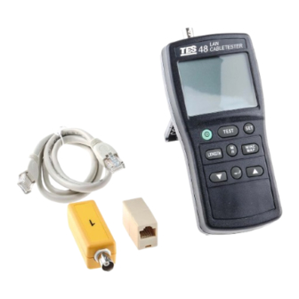
1. INTRODUCTION The LAN Cablemeter is an easy to use and effective cable test instrument with the ability to identify cable failures, check wiring, and measure cable length of UTP (Unshielded twisted pair cable), FTP (Foil – screened (shielded) twisted pair cable) cables, and COAX (coaxial cable) cables. -
Page 4: Product Profile
2. PRODUCT PROFILE TEST LCD Display: Custom large size LCD. For more information, press ▼ ▲ key to display the additional information. TEST key: Test the attached cable and indicate pass or failure information based on the specified parameters for the selected cable. - Page 5 SET key: Access to cable selection, cable calibration, and other test instrument settings. LENGTH measurement key: Measure the length of each pair of twisted pair cable or coaxial cables in metres or feet and tests for anomalies. WIREMAP test key: To display wiring connections, opens, shorts, ...
-
Page 6: Specifications
3. SPECIFICATIONS Cable Length Measurements Range: 1.0 to 350m (2-999 ft) Accuracy: 5% + 1m (5% +3ft) Cables > 150 meters: 10% + 1m (10% + 3 ft) Resolution: Measurement Unit in Feet: Cables < 100 ft: 0.5 ft , Cables > 100 ft:1ft Measurement Unit in Meters. - Page 7 COAX Termination Measurements Any loop resistance value between 5 and 350Ω is interpreted as a termination resistance. Resistance value below 5Ω is considered a short and resistance value greater than 350Ω is not displayed. General Specifications Power: Six AAA size 1.5V batteries. Low Battery Indication: Display shown “...
-
Page 8: Setup Selections
4. SETUP SELECTIONS The setup mode allows the user to select and calibrate the instrument for particular cable characteristics. Once set, these parameters are stored and remain in the instrument memory even when it is turned off. Setup items: 1. Select a cable type (UTP, FTP or COAX). 2. - Page 9 Selecting a Cable Type Procedure: 1. Press the “SET” key to enter setup mode. 2. Press either the ▼or ▲key until the desired “cable” type is displayed, then press the enter key. 3. Press either the ▼or ▲keys until the desired “category” is displayed, then press the enter key.
- Page 10 5. Press either the ▼or ▲key to choose to preceed or not preceed tests with the “ ” function, then press the enter key. 6. Press either the ▼or ▲ key to enable or disable “ ”, then press enter key. 7.
-
Page 11: Calibrating Cable Length
5. CALIBRATING CABLE LENGTH The characteristic cable parameters are now determined for the particular cable selected. Cables from different batches or manufacturers may have characteristic variations of up to 20% from the nominal published specifications. These variations will in turn cause deviations in length measurement. - Page 12 Note: 1. Hidden calibrating cable length mode. Press key to turn off the meter. Press and hold down the ▼and ▲keys then press the to turn on the meter, until LCD shows “ ”. Press the ▼ or ▲key to cycle display through “ ”...
-
Page 13: Operating
6. OPERATING A). Test Cables The TEST function tests the attached cable based on the cable’s compliance with the parameters stored in the tester for the selected cable. To test a cable, perform the following procedures. 1. Select cable type under test. 2. - Page 14 Good cable, cable remote unit ID#1 detected. Good cable, no cable remote unit detected or the tester may not sense the remote unit. If testing coaxial cable with a termination, the tester dispalys the total resistance of the cable wires and the terminetion. ST = 49.0 Ω...
- Page 15 Test Failures (without remote unit) FAILURE DISPLAY DESCRIPTION Short Display shorted wires and most (UTP/FTP) likely distance to the short. Display open wires, the distance OPEN to the break and whether it is at the near or far end of the cable. Display incorrect wire pairings Split Pair based on the selected cable...
- Page 16 Test Failures with remote unit FAILURE DISPLAY DESCRIPTION Display the incorrect wiring of the Mis wire end connectors. Display the broken wire and the Open distance to the break. Indicates the length of the pairs Pair Length within a cable are abnormal different.
- Page 17 B). Cable Length Measurment The tester measures the length of both twisted-pair. If the tester is not calibrated to the cable under test, then factory default cable characteristisc are used to compute the length. If a more accurate length measurement is desired, refer to “CALIBRATING CABLE LENGTH”...
- Page 18 For 50m UTP C). WIRE MAP CHECKING Use the wiremap function and remote identifier unit (ID), to determine the wiring status of both the near end and far end of the cable. Wire Map measure procedure. 1. Select cable type under test. 2.
- Page 19 Wire Map Failure Using remote unit (ID). FAILURE DISPLAY WIRING DESCRIPTION Alternately display Short an “s” with actual (near end) wire numbers of each wire shorted. Alternately display “o” with the number Open each open- circuit wire. Displays the wiring detected instrument.
-
Page 20: Saving And Recalling Data In Memory
7. SAVING AND RECALLING DATA IN MEMORY 1. Press the “MR” key once to store one set of data in the internal memory. The LCD shows M and the memory location numbers (01 to 99). If no test data is displayed, this function is inoperative. 2. -
Page 21: Maintenance
8. MAINTENANCE 1. Cleaning: Periodically wipe the case with a damp cloth and mild detergent. Do not use abrasives or solvents. Clean and dry as required. 2. Battery replacement: When the LCD display shows “ ”, the batteries have insufficient power to operate the instrument correctly and must be replaced. - Page 22 Limited Warranty This meter is warranted to the original purchaser against defects in material and workmanship for 3 years from the date of purchase. During this warranty period, RS Components will, at its option, replace or repair the defective unit, subject to verification of the defect or malfunction.
- Page 23 Africa Japan RS Components SA RS Components Ltd. P.O. Box 12182, West Tower (12th Floor), Vorna Valley, 1686 Yokohama Business Park, 20 Indianapolis Street, 134 Godocho, Hodogaya, Kyalami Business Park, Yokohama, Kanagawa 240-0005 Kyalami, Midrand Japan South Africa www.rs-components.com www.rs-components.com Asia U.S.A RS Components Pte Ltd.
Need help?
Do you have a question about the 48 and is the answer not in the manual?
Questions and answers