Table of Contents

Subscribe to Our Youtube Channel
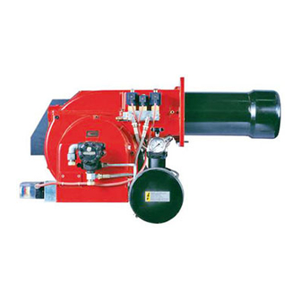
Related Manuals for CIB UNIGAS PN91


Summary of Contents for CIB UNIGAS PN91
- Page 1 PN91 - PN92 - PN93 LMV2x Microprocessor-controlled Heavy oil burners MANUAL OF INSTALLATION - USE - MAINTENANCE BURNERS - BRUCIATORI - BRULERS - BRENNER - QUEMADORES - ГОРЕЛКИ M039535CA Rel 0.1 11/2023 M12923CA Rel. 0.7 03/2016...
-
Page 2: General Introduction
DANGERS, WARNINGS AND NOTES OF CAUTION THIS MANUAL IS SUPPLIED AS AN INTEGRAL AND ESSENTIAL PART OF THE PRODUCT AND MUST BE DELIVERED TO THE USER. INFORMATION INCLUDED IN THIS SECTION ARE DEDICATED BOTH TO THE USER AND TO PERSONNEL FOLLOWING PRODUCT INSTALLATION AND MAINTENANCE. -
Page 3: Directives And Standards
3b) FIRING WITH GAS, LIGHT OIL OR OTHER FUELS DIRECTIVES AND STANDARDS Gas burners GENERAL European directives The burner shall be installed by qualified personnel and in compliance -Regulation 2016/426/UE (appliances burning gaseous fuels) with regulations and provisions in force; wrong installation can cause -2014/35/UE (Low Tension Directive) injuries to people and animals, or damage to property, for which the -2014/30/UE (Electromagnetic compatibility Directive) -
Page 4: Symbols Used
Burner data plate Type For the following information, please refer to Model Gas - Light oil burners Year the data plate: European Directives S.Number -Regulation 2016/426/UE (appliances burning gaseous fuels) burner type and burner model: must be Output Oil Flow -2014/35/UE (Low Tension Directive) reported in any communication with the Fuel... -
Page 5: Burner Model Identification
Burner model identification Burners are identified by burner type and model. Burner model identification is described as follows. Type PN91 Model (1) BURNER TYPE PN91 - PN92 - PN93 N - Heavy oil, viscosity 50cSt (7° E) @ 50° C ... -
Page 6: Technical Specifications
Technical Specifications PN91 N.. PN92 N.. PN93 N.. PN91 P.. PN92 P.. PN93 P.. BURNER Output 698 - 2093 849 - 2558 550 - 4100 698 - 2093 849 - 2558 550 - 4100 min - max kW Fuel N - Heavy oil, viscosity <= 50cSt (7° E) @ 50° C P - Petroleum, viscosity 89cSt (12°... -
Page 7: Performance Curves
Data are referred to standard conditions: atmospheric pressure at 1013mbar, ambient temperature at 15°C. Performance Curves To get the input in kcal/h, multiply value in kW by 860. Data are referred to standard conditions: atmospheric pressure at 1013mbar, ambient temperature at 15°C. PN91 PN92 1200 1600... - Page 8 PN510 PN515 1200 2000 2800 3600 4400 5200 1000 1800 2600 3400 4200 PN520 PN525 1600 2400 3200 4000 4800 5600 6400 7200 8000 1500 2500 3500 4500 5500 6500 7500 8500 NOTE: The performance curve is a diagram that represents the burner performance in the type approval phase or in the laboratory tests, but does not represent the regulation range of the machine.
- Page 9 Burner flange (Dibujo indicativo) TIPO A (AS) A (AL) AA AB AC AD AE B (BS) B (BL) BB Omin Omax PN91 1329 1519 152 276 221 35 473 441 1031 533 1129 464 533 441 596 262 292 228 360 466 M12 424...
- Page 10 RN525 P-.PR.L.RU.A.EA Overall dimensions (mm) 1295 1725 1195...
- Page 11 HYDRAULIC DIAGRAMS 3LMD-25 - KEYS OIL TRAIN MANUFACTURER INSTALLER Filter Pump and pressure governor Electrical preheater tank Temperature probe Temperature probe oil inlet Temperature probe Thermometer 3-way solenoid valve Flexible hose oil outlet Flexible hose Flexible hose Oil distributor Pressure gauge with manual valve (*optional) Low thermostat - TCI Pressure governor with actuator Flexible hose...
-
Page 12: Installing The Burner
Packing Burners are despatched in wooden crates whose dimensions are: PN91-92-93 1730mm x 1280mm x 1020mm (L x P x H) Packing cases of this kind are affected by humidity and are not suitable for stacking. The following are placed in each packing case: burner;... - Page 13 Fitting the burner to the boiler To install the burner into the boiler, proceed as follows: make a hole on the closing door of the combustion chamber as described on paragraph “Overall dimensions”) place the burner to the boiler: lift it up and handle it according to the procedure described on paragraph “Handling the burner”; place the stud bolts (5) on boiler’s door, according to the burner drilling template described on paragraph “Overall dimensions”;...
-
Page 14: Electrical Connections
ELECTRICAL CONNECTIONS WARNING! Respect the basic safety rules. make sure of the connection to the earthing system. do not reverse the phase and neutral connections. fit a differential thermal magnet switch adequate for connection to the mains. WARNING! before executing the electrical connections, pay attention to turn the plant’s switch to OFF and be sure that the burner’s main switch is in 0 position (OFF) too. - Page 15 Connecting the oil heating resistors 2.4 - 4.5 kW 8 - 12 kW 400 V 230V 400 V 230V Fig. 3 Fig. 4 18 - 24 kW ELECTRIC MOTOR CONNECTION 400 V 230V 400 V 230V Fig. 6 Fig. 5 Double-pipe and single-pipe system The pumps that are used can be installed both into single-pipe and double-pipe systems.
-
Page 16: Oil Pumps
Oil pumps PN91: SUNTEC TA2 / DANFOSS KSM50 PN92/93/510: SUNTEC TA3 / DANFOSS KSM70 Danfoss KSM.. Oil viscosity 2.5 ÷ 450 cSt Oil temperature -10 ÷ 160 °C Max. suction pressure 4 bar Min. suction pressure -0.45 bar to avoid gasing Max. - Page 17 Care must be taken when installing the pump not to force the pump shaft along its axis or laterally to avoid excessive wear on the joint, noise and overloading the gears. Pipes should not contain air pockets. Rapid attachment joint should therefore be avoided and threaded or mechanical seal jun- ...
-
Page 18: Light Oil Operation
PART II: OPERATION PART II: OPERATION LIMITATIONS OF USE THE BURNER IS AN APPLIANCE DESIGNED AND CONSTRUCTED TO OPERATE ONLY AFTER BEING CORRECTLY CONNEC- TED TO A HEAT GENERATOR (E.G. BOILER, HOT AIR GENERATOR, FURNACE, ETC.), ANY OTHER USE IS TO BE CONSIDE- RED IMPROPER AND THEREFORE DANGEROUS. -
Page 19: Control Panel
PART II: OPERATION Control panel PN91 - PN92 - PN93 High flame lamp Low flame lamp Ignition transformer operation CMF Manual operation switch 0= Off 1= High flame 2= Low flame 3= Automatic Fan motor thermal cutout intervention Burner lockout... - Page 20 PART II: OPERATION Recommendations to design heavy oil feeding plants This paragraph is intended to give some suggestions to make feeding plants for heavy oil burners. To get a regular burner operation, it is very important to design the supplying system properly. Here some suggestions will be mentioned to give a brief description. The term “heavy oil”...
- Page 21 PART II: OPERATION Viscosity units conversion table Saybolt Cinematics Saybolt Redwood Engler Degrees Seconds Redwood Seconds viscosity Seconds Seconds no.1 (°E) Universal no..2 (Admiralty) Centistokes (cSt) Furol (SSF) (Standard) (SSU) 2.56 1.16 32.1 1.31 36.2 1.58 44.3 5.83 10.3 1.88 52.3 6.77 13.1...
- Page 22 PART II: OPERATION VISCOSITY vs TEMPERATURE DIAGRAM FOR COMBUSTIBLE OILS 1000 PUMPING LIMIT TEMPERATURE (°C) LIGHT OIL 1,3°E AT 20°C HEAVY OIL 2,4°E AT 50°C HEAVY OIL 4°E AT 50°C HEAVY OIL 7,5°E AT 50°C HEAVY OIL 10°E AT 50°C HEAVY OIL 13°E AT 50°C HEAVY OIL 22°E AT 50°C HEAVY OIL 50°C...
-
Page 23: Hydraulic Diagrams
PART II: OPERATION Indicative diagram showing the oil temperature at burner pump inlet vs. oil viscosity Example: if the oil has a 50°E @ 50°C viscosity, the oil temperature at the pump inlet should be 80°C (see diagram). OIL TEMPERATURE FOR PUMP FEEDING TEMPERATURE (°C) Fig. - Page 24 Fig. 11 3ID00014 v2 Hydraulic diagram - Two or more burners configuration BURNER 2 SEE THE BURNER 1 SEE THE BURNER P&ID BURNER P&ID HEATING MEDIUM INLET HEATING MEDIUM OUTLET PRESSURE GOVERNOR UNIT OIL PUMPING UNIT DAILY TANK UNIT OIL PUMPING UNIT HEATING MEDIUM INLET PIPE HEATING SYSTEM: SEE THE SPECIFIC MAIN TANK INLET...
- Page 25 Fig. 12 - 3ID0023 v2 - Hydraulic diagram - Single burner configuration BURNER 1 SEE THE BURNER P&ID LEGEND OIL TRAIN OIL TRAIN Main tank OIL PUMPING UNIT Main tank Manual valve Filter OIL PUMPING UNIT Pump coupled to electrical motor Safety valve Manual valve HEATING MEDIUM INLET...
- Page 26 PART II: OPERATION Adjusting oil flow rate The oil flow rate can be adjusted choosing a nozzle that suits the boiler/utilisation output and setting the delivery and return pressure values according to the ones quoted on the following charts. FLUIDICS NOZZLE: REFERENCE DIAGRAM (INDICATIVE ONLY) Atomisation angle FLOW RATE kg/h Indicative...
- Page 27 PART II: OPERATION Progressive and fully modulanting oil burners are equipped with electronic multi-thermostat Danfoss MCX, whose operation is con- trolled by thyristor. (for details refer to the attached technical documentation) Fig. 13 - Danfoss MCX Fig. 14 -Probe connections (Danfoss MCX)
-
Page 28: User Interface
PART II: OPERATION ADJUSTING AIR AND FUEL RATE ATTENTION: before starting the burner up, be sure that the manual cutoff valves are open. Be sure that the mains switch is closed. ATTENTION: During commissioning operations, do not let the burner operate with insufficient air flow (danger of formation of carbon monoxide);... - Page 29 PART II: OPERATION Keys (+ & - )= ESC By pressing + and - at the same time, the ESCAPE function is perfomed: to enter a lower level menu The display will show these data: Lock+unlock codes Flame Open valves Ignition transformers energised Fan motor energised Oil pre-heater energised...
- Page 30 PART II: OPERATION Ph30 t1 = tempo preventilazione t1 = prepurge time Ph36 Verso posizione accensione Traveling to the ignition position Ph38 t3 = tempo preaccensione t3 = preignition time TSA1= 1st safety time (ignition transformer Ph40 TSA1 = primo tempo sicurezza (trasformatore accensione ON) TSA1 = primo tempo sicurezza (trasformatore accensione OFF) TSA1 = 1st safety time (ignition transformer OFF)
-
Page 31: Info Level
PART II: OPERATION The burner and consequently the LMV2x.. are factory set; the air and fuel curves as set as well. Info level To enter the Info level, proceed as follows: in any menu position, press keys + and - at the same time, then the program will start again: the display will show OFF. until the display will show InFo, Press the enter (InFo) key then il will show the first code (167) flashing, on the right side it will show the data entered. -
Page 32: Parameter Description
PART II: OPERATION Parameter Description Cubic meters of fule (resettable) Operating hours (resettable) Device operating hours Burners start-ups (resettable) Total number of start-ups Burner number (i.e. serial number) Software version Software date Device serial number Customer code Version Free Example: choose parameter 102 to show the date the display shows parameter 102 flashing on the left and characters ._._ on the right. -
Page 33: Service Level
PART II: OPERATION Diagnostic code (in the example “diagnostic code:3”). Record the codes and find out the fault in the Error table. To perform the reset, press InFo for one second: The unit displays an event which does not lead to shutdown. The display shows current error code c: alternating with diagnostic code d: Press InFo to return to the display of phases. - Page 34 PART II: OPERATION .the first parameter will be “954”: the percentage of flame is shown on the right. By pressinf + or - it is possible to scroll up/down the parameter list. Once the last parameter is accessed (143) by pressing + , the End message will blink. Press InFo for more than three seconds or for more than three seconds orto return to the normal display.
-
Page 35: Oil Circuit
PART II: OPERATION Oil circuit The fuel is pushed into the pump 1 to the nozzle 3 at the delivery pressure set by the pressure governor. The solenoid valve 2 stops the fuel immission into the combustion chamber. The fuel flow rate that is not burnt goes back to the tank through the return circuit. The spill-back nozzle is feeded at constant pressure, while the return line pressure is adjusted by means of the pressure governor controlled by an actuator coupled to an adjusting cam. -
Page 36: Routine Maintenance
PART III: MAINTENANCE PART III: MAINTENANCE At least once a year carry out the maintenance operations listed below. In the case of seasonal servicing, it is recommended to carry out the maintenance at the end of each heating season; in the case of continuous operation the maintenance is carried out every 6 months. -
Page 37: Self-Cleaning Filter
PART III: MAINTENANCE Thecnical procedure of self cleaning filters substitution (valid for all models) 1 Close the bowl valve before the self cleaning filter 2 Switch off any electrical equipment on board on the filter (example motorization or heaters) WARNING! Drain the system by unscrewing the drain screw on the bottom of the self cleaning filter 3 Disconnect the outlet pipe from the cover of the self cleaning filter 4 Remove the cover with all the filter pack, leaving only the bowl on the line 5 Clean any residue on the bottom of the bowl and clean the seat of the O-ring seal... - Page 38 PART III: MAINTENANCE Fig. 20 1 Inlet 2 Return 3 Lance opening 4 Heating wire (only for oil viscosity > 110 cSt @ 50 °C) 5 Cartdrige-type heater H Cover Fig. 21 L Oil lance E Oil piping connections Removing the oil gun, replacing the nozzle and the electrodes ATTENTION: avoid the electrodes to get in touch with metallic parts (blast tube, head, etc.), otherwise the boiler operation would be compromised.
- Page 39 PART III: MAINTENANCE Setting the combustion head position If necessary, change the combusiton head position: to let the burner operate at a lower output, loose the VB screw and move progres- sively back the combustion head towards the MIN position, by turning clockwise the VRT ring nut. Fasten VB screw when the adjustment is accomplished (Fig.
-
Page 40: Seasonal Stop
PART III: MAINTENANCE Cleaning and replacing the detection photoresistor When cleaning the photoresistive detector, always use a clean cloth. If necessary, remove it from its slot to replace it. Seasonal stop To stop the burner in the seasonal stop, proceed as follows: turn the burner main switch to 0 (Off position) disconnect the power mains close the fuel valve of the supply line... -
Page 41: Troubleshooting
PART III: MAINTENANCE TROUBLESHOOTING CAUSES/TROUBLES MAIN SWITCH OFF LINE FUSES BLOWN MAXIMUM THERMOSTAT MALFUNCTION FAN THERMAL CUTOUT TRIPPED AUXILIARY FUSE BLOWN OIL RESISTOR FAULTY OIL ENABLING THERMOSTAT TRIPPED ... -
Page 42: Burner Exploded View
BURNER EXPLODED VIEW ITEM DESCRIPTION ITEM DESCRIPTION ITEM DESCRIPTION NIPPLE 5.2.2 GASKET AIR INTAKE DAMPER ELBOW 5.2.3 GAS BLEEDING VALVE AIR INTAKE DAMPER NIPPLE 5.2.4 THERMOMETER AIR INTAKE PUMP 5.2.5 MUFF LOUVER SHAFT 2.1.1 POWER CONTROLLER COVER LOUVER SHAFT 2.1.2 FRONT CONTROL PANEL REDUCTION ADJUSTING CAM SHAFT... - Page 44 USER MANUAL OF MULTI-THERMOSTAT MCX06C MCX06C is a multi-thermostat with four 100k NTC inputs. It can control up to 4 temperatures showing them (not more than 2 at the same time) on a couple of displays. It is used to check and adjust oil heater temperatures. User interface: Device: ESC button/...
- Page 45 Menu: To enter the menu below, keep pushing ENTER for more than 3 s. Menu code Sub-menu Function Notes code Probes values You can see in sequence the 4 probe values (UP and DOWN keys): the probe code is on display A (Pb1,..., Pb4) and the probe value is on display B (not fitted or out of work probes show “----“).
- Page 46 Set point adjustment: All the parameters inside the Par menu are locked by a password. The user can modify only set points (menu rEG), without using any passwords. The oil viscosity at the nozzle, should be about 1,5° E, which guarantees correct and safe functioning of the burner. The temperature values in the table, guarantee the respect of that parameter and are valid when the pre heating tank is installed on the burner.
- Page 48 C.I.B. UNIGAS S.p.A. Via L.Galvani, 9 - 35011 Campodarsego (PD) - ITALY Tel. +39 049 9200944 - Fax +39 049 9200945/9201269 web site: www.cibunigas.it - e-mail: cibunigas@cibunigas.it Note: specifications and data subject to change. Errors and omissions excepted.
- Page 49 AZL2x - LMV2x/3x Burner Management System Service manual 03/2023 M12916CD Rev. 3.4...
- Page 50 INDEX MICROPROCESSOR CONTROLLED SYSTEM..........................6 User interface....................................6 Parameters level (heating engineer)............................... 8 Setting menu....................................9 Block 000: Internal Parameter ..............................10 Block 100: General information..............................10 Block 200: Burner control................................13 Block 400: Setting air/fuel ratio curves............................25 Block 500: Air/fuel ratio control ..............................26 Block 600: Actuators ..................................
- Page 51 DANGERS, WARNINGS AND NOTES OF CAUTION THIS MANUAL IS SUPPLIED AS AN INTEGRAL AND ESSENTIAL PART OF THE PRODUCT AND MUST BE DELIVERED TO THE USER. INFORMATION INCLUDED IN THIS SECTION ARE DEDICATED BOTH TO THE USER AND TO PERSONNEL FOLLOWING PRO- DUCT INSTALLATION AND MAINTENANCE.
- Page 52 DIRECTIVES AND STANDARDS do not leave the equipment exposed to weather (rain, sun, etc.) unless expressly required to do so; Gas burners European directives: do not allow children or inexperienced persons to use equipment; - Directive 2009/142/EC - Gas Appliances; The unit input cable shall not be replaced by the user.
- Page 53 -EN 55014-1Electromagnetic compatibility - Requirements for household appliances, electric tools and similar apparatus. -UNI EN 676 (Gas Burners; -CEI EN 60335-1(Household and similar electrical appliances - Safety. Part 1: General requirements; - EN 50165 Electrical equipment of non-electric appliances for household and similar purposes.
- Page 54 MICROPROCESSOR CONTROLLED SYSTEM The control system is made of the Siemens LMV central unit that performs all the burner control functions and of the Siemens AZL local programming unit that interfaces the system with the user. Keys Burner AZL2.. Air actuator Fuel actuator LMV2..
- Page 55 The keys functions are the following: Key F Used to adjust the “fuel” actuator position (Fuel): : While pressing the F key, the “fuel” actuator position can be changed by means of the + and - keys. Key A Used to adjust the “air” actuator position (Air): While pressing the A key, the “air”...
- Page 56 Parameters level (heating engineer)
- Page 57 Setting menu The seeting menu is divided into different blocks: Bloc. Descrizione Description Password Internal parameters OEM / Service Informazioni generali General OEM / Service / Info Controllo bruciatore Burner control OEM / Service Controllo bruciatore (solo LMV26) Burner control (LMV26 only) OEM / Service Curve rapporto Ratio curves...
- Page 58 Block 000: Internal Parameter Param. Descrizione Description Password Password livello assistenza (ingegnere del Password heating engineer (4 characters) calore) Password livello OEM (costruttore del brucia- Password OEM (5 characters) tore) Start backup / restore via AZL2.../ PC sof- tware (set parameter to 1) Index 0: Create backup Index 1: Execute restore Error dia- Start backup/restore via AZL2x/PC gnostics via negative values...
- Page 59 Frequenza di rete Mains frequency 0 = 50 Hz 0 = 50 Hz Service / Info 1 = 60 Hz 1 = 60 Hz Luminosità display Display brightness Service / Info Tempo dopo il quale, se non viene premuto nessun tast il software esce dalla modalita Timeout for menu operation (default value = programmazione (valore fabbrica = 60min - 60min - range: 10 - 120 min)
- Page 60 Numero totale di partenze (non azzerabile) Total number of startups Service / Info Volume combustibile (azzerabile da OEM) Fuel volume (resettable by OEM) Service / Info Fuel 1(secondo combustibile)Ore di eserci- Fuel 1: Operation hours resettable Service / Info zio (azzerabile da Service) Fuel 1 (secondo combustibile) Numero di Fuel 1: Number of startups resettable Service / Info...
- Page 61 Block 200: Burner control Param. Descrizione Description Password Modalità funzionamento bruciatore ( rampa Burner operating mode (fuel train, modula- combustibile, modulante / multistadio, servo- ting / multistage, actuators, etc..) comandi, ecc.) __= non definito (cancellazione curve) __= undefined (delete curves) 1 = accensione diretta a gas (G mod) 1 = gas direct ignition (G mod) 2 = accensione tramite pilota gas con attacco...
- Page 62 15 = gas rampa Gp1 modulante pneumatico 15 = Gp1 mod pneu without actuator senza servomotori (Gp1 mod pneu) 16 = Gp2 mod pneu without actuator 16 = gas rampa Gp2 modulante pneumatico 17 = Lo 2-stage without actuator senza servomotori (Gp2 mod pneu) 18 = Lo 3-stage without actuator 17 = olio LO 2 stadi senza servomotori 19 = G mod gas actuator only...
- Page 63 Gas: sonda rilevazione fiamma attivo (valore Gas: active detector flame evaluation (default fabbrica = 1) value = 1) OEM / Service 0 = QRB../QRC.. 1 = ION / QRA.. Gas: Preventilazione (valore fabbrica = 1) Gas: Pre-purging (default value = 1) 1 = attivo 1 = active 0 = non attivo...
- Page 64 Gas: Pressostato gas di minima (default = 1) Gas: Pressure switch-min input 0 = inattivo 0 = inactive 1 = pressostato gas di minima (a monte val- 1 = pressure switch-min (upstream of fuel vola V1) valve 1 (V1)) 2 = controllo perditavalvole via pressostato 2 = valve proving via pressure switch-min OEM / Service (montato tra le valvole V1 e V2)
- Page 65 Gas: tempo pressione atmosferica controllo Gas: proving test time atmospheric pres- tenuta (valore fabbrica = 10s - range impo- sure (default value = 10s - range:0.2s - 60s) stazione:0.2s - 60s) Gas: tempo riempimento controllo tenuta Gas: proving test filling time (default value = (valore fabbrica = 3s - range imposta- 3s - range:0.2s - 10s) zione:0.2s - 10s)
- Page 66 Olio: Intervallo 1 (valore fabbrica = 2s - Oil: Interval 1 (default value = 2s - OEM / Service range impostazione:0.2s - 60min) range:0.2s - 60min) Olio: tempo di sicurezza 2 (TSA2) (valore Oil: safety time 2 (TSA2) (default value = 3s fabbrica = 3s - range impostazione:0.2 - 10s) - range:0.2 - 10s) Olio: Intervallo 2 (valore fabbrica = 2s -...
- Page 67 Block 300: Burner control (only with LMV26) Param. Descrizione Description Password Combustibile 1 : Modalità funzionamento bru- Fuel 1 : Burner operating mode (fuel train, ciatore ( rampa combustibile, modulante / modulating / multistage, actuators, etc..) multistadio, servocomandi, ecc.) __= non definito (cancellazione curve) __= undefined (delete curves) 1 = accensione diretta a gas (G mod) 1 = gas direct ignition (G mod)
- Page 68 11 = olio 2 stadi con accensione tramite pilota 11 = LoGp 2-stage (LOGp 2-stage) 12 = Lo mod 2 fuel valves 12 = olio modulante con 2 valvole combusti- 13 = LoGp mod 2 fuel valves bile (LOmod 2 valvole) 14 = G mod pneu without actuator 13 = olio modulante con 2 valvole combusti- 15 = Gp1 mod pneu without actuator...
- Page 69 Combustibile 1 - Gas: tempo di preaccen- Fuel 1 - Gas: Preignition time (default value = sione (valore fabbrica = 2s - range imposta- 2s - range: 0.2s - 60min) OEM / Service zione:0.2s - 60min) Combustibile 1 - Gas: tempo di sicurezza 1 Fuel 1 - Gas: Safety time 1 (TSA1) (default (TSA1) (valore fabbrica = 3s - range impo- value = 3s - range: 0.2 - 10s)
- Page 70 Limite ripetizioni perdita di fiamma (valore Repetition limit loss of flame (default value= 2 fabbrica = 2 - range impostazione:1 - 2) - range:1 - 2) Fuel 1 - Gas: execution proving test (default Combustibile 1 - Gas: esecuzione controllo value= 2) tenuta (valore fabbrica = 2) 0 = no controllo tenuta...
- Page 71 Fuel 1 - Oil: prepurging (default value = 1) Combustibile 1 - Olio: preventilazione (valore fabbrica = 1) 0 = deactivated 1 = attivo 1 = activated 0 = non attivo 0 = deactivated OEM / Service In ambito civile la norma EN267 rende obbli- WARNING: in the civil field, the prepurge is gatoria la preventilazione.
- Page 72 Limite ripetizioni perdita di fiamma (valore Repetition limit value loss of flame (default fabbrica = 2 - range impostazione:1 - 2) value = 2 - range:1 - 2) Fuel 1 - Oil: time oil ignition (default value = Combustibile 1 - Olio: tempo iniezione olio (valore fabbr.
- Page 73 Block 400: Setting air/fuel ratio curves Param. Descrizione Description Password Curve controllo servocomando combustibile Ratio control curve fuel actuator (F): it acces- (F): si accede alla lista dei punti da impostare ses to the parameter list of the points to be set OEM / Service (da P0 a P9) - consultare paragrafo “Imposta- (P0 to P9) - see paragrapf “Setting the curves”...
- Page 74 Block 500: Air/fuel ratio control Param. Descrizione Description Password No-flame position fuel actuator Posizione servocomando combustibile in assenza di fiamma (no-flame) Indice 0 = posizione di sosta = 0° Index 0 = no-load position = 0° OEM / Service Indice 1 = posizione preventilazione = 0° Index 1 = prepurge position = 0°...
- Page 75 Activation of VSD / PWM fan (PWM = Pulse- Width Modulation) Activation of VSD / PWM fan OEM / Service 0=deactived 1=actived (PWM = Pulse-Width Modulation) Parameter 544 Modulation Modulation Modulation Modulation Actuator Actuating speed param- Max. delta between the curve points eter 613 OEM / Service Actuator...
- Page 76 Block 600: Actuators Param. Descrizione Description Password Impostazione punto di riferimento Selection of reference point Indice 0 = combustibile Index 0 = fuel Indice 1 = aria Index 1 = air 0 = chiuso (<0°) 0 = closed (<0°) 1 = aperto (>90°) 1 = open (>90°) Direzione rotazione del servocomando Actuator’s direction of rotation...
- Page 77 Tipo di riferimento dei servocomandi index 0 = fuel (default = 0 (riferimento stan- dard) Type of referencing index 1 = air (default = 0 (riferimento stan- Index 0 = fuel dard) Index 1 = air 0 = standard 0 = standard 1 = fermo entro il raggio utile 1 = stop within usable range 2 = fermi interni (SQN1...)
- Page 78 Configurazione uscita analogica % di carico Configuration of analog output (default value (valore fabbrica = 0) = 0) 0 = DC 0..10 V 0 = DC 0..10 V OEM / Service 1 = DC 2..10 V 1 = DC 2..10 V 2 = DC 0/2..10 V 2 = DC 0/2..10 V ATTENTION: as for SQM3x actuators, set the direction according to the acutator function.
- Page 79 Block 700: Error history Param. Descrizione Description Password Storico errori: 701 - 725.01.codice Error history: 701 - 725.01.code Service / Info Storico errori: 701 - 725.02.codice diagnostico Error history: 701 - 725.02.diagnostic code ° Service / Info Storico errori: 701 - 725.03.classe errore Error history: 701 - 725.03.error class °...
- Page 80 Block 900: Process data Param. Descrizione Description Password Potenza attuale (valore fabbrica = 0% - range Current output (default value = 0% - range = impostazione = 0-100%) 0-100%) Service / Info Indice 0 = combustibile Index 0 = fuel Indice 1 = aria Index 1 = air Posizione incrementale servocomandi (valore...
- Page 81 Actuators references An incremental transducer is used to ensure position feedback. Referencing of the actuators must be performed after power-on. In addition, at the end of each shutdown in phase 10, the actuators are referenced to ensure that individual stepping errors, which could lead to shutdown, do not accumulate.
-
Page 82: Commissioning The Burner
COMMISSIONING THE BURNER The LMV2x complete programming must be performed on units that has never been set before or reset units (e.g. spare parts). The programming procedure is performed by setting the following main parameters: if LMV.. is a spare part, insert burner ID (parameter 113) at least 4 digit. type of fuel train (parameter “201”) air/fuel ratio curvepoints (Block “400”) maximum load percentage (parameter “546”) - Page 83 the types of fuel trains are the following: Param. Descrizione Description Password Modalità funzionamento bruciatore ( rampa Burner operating mode (fuel train, mod / multi- comb., mod. / multistadio, servocom., ecc.) stage, actuators, etc.) __= non definito (cancellazione curve)___= __= undefined (delete curves) 1 = accensione diretta a gas (G mod) 1 = gas direct ignition(G mod) 2 = accensione tramite pilota gas con attacco...
- Page 84 Lo 3-stage In the example the Gmod gas train has been set (Configuration “1”). Choose the fuel train by pressing ENTER, then press “+” / “-”. Press ENTER to confirm: number “1” will appear on the right side of the display.
- Page 85 CAUTION: at the first burner adjustment, it is recommended to set the maximum output P9 at the same value (or little higher) of the ignition point, in order to safely reach point P9 next (see next paragraph). By pressing “+” the display will show: The burner is ready to startup.
-
Page 86: Warm Setting
Warm setting Once pressed button “enter” and the chain thermostats open (X5-03 terminals), the LMV.. show Ph12.Then close the chain termostat and the unit performs the prepurge cycle (see “Phases List”) and stops at the ignition point P0 without ignition anyway. By pressing “+”, the burners lights abd the air/fuel ratio can be properly set in presence of flame. -
Page 87: Cold Setting
P5, keep pressing “-” unitl “Calc” is displayed. The curve will be processed again downwards point P1. Fuel deviation between two following points: 25°max. 12 press “-” to go through the lower points and check the combustion values, if necessary change the points as described above. 13 By pressing ESC, at the end of the points adjusments, the parameter “546”... - Page 88 BURNER STARTUP WITH LMV2x ALREADY PROGRAMMED Once the LMV turns on, the AZL display will show The burners is basically factory set. The air/fuel ratio curve is set with the maximum output point P9 a little higher or equal to P0. To adjust the burner on the plant site, adjust the maximum output point to the flow rate values really requested.
- Page 89 Set the air/fuel ratio curvepoints as described on chapter “Programming the LMV2x” Note: the other phases are Ph60 = operation (OP= in modulation) Ph62 = travelling to shutdown Ph70 = off but in prepurge after the burntime Ph72 = travelling to postpurging Ph74 = postpurge (countdown is displayed) Press ESC the parameter “546”...
- Page 90 Reset / manual lockout The system can be manually locked by simultaneously pressing the ENTER (InFo) button and any other button on the AZL2..This function allows the user to stop the system from the operating level should an emergency occur. When making a reset, the following actions are carried out: Alarm relay and the fault display are off ...
- Page 91 Entering the Parameter levels By means of a proper use of the keys, it is possible to enter the various level parameters, as shown in the following flow chart: The burner and consequently the LMV2x.. are factory set; the air and fuel curves as set as well.
- Page 92 Info level To enter the Info level, proceed as follows: in any menu position, press keys + and - at the same time, then the program will start again: the display will show OFF. , until the display will show InFo, Press the enter (InFo) key then il will show the first code (167) flashing, on the right side it will show the data entered.
- Page 93 10 Press InFo for more than three seconds or for more than three seconds orto return to the normal display. If a message like the one below is shown during operation, it means that the burner is locked out and the Errore code is shown (in the example “error code:4”); this message is alternating with another message Diagnostic code (in the example “diagnostic code:3”).
- Page 94 Service level To enter the Service mode, press InFo until the display will show: The service level shows all the information about flame intensity, actuators position, number and lock codes: Parameter Description Flame intensity % output, if set = automatic operation Actuators position, 00=combustibile;...
- Page 95 PHASES LIST Fase /Phase Funzione Function Ph00 Fase blocco Lockout phase Ph01 Fase di sicurezza Safety phase Ph10 t10 = tempo raggiungimento posizione riposo t10 = home run Ph12 Pausa Standby (stationary) t22 = tempo di salita ventilatore (motore ventilatore t22 = fan ramp up time (fan motor = ON, safety Ph22 = ON, valvola intercettazione di sicurezza = ON)
- Page 96 BACKUP PARAMETER WITH AZL2x On the AZL2x you can save the configuration to download on another appliance LMV. To do this: access up, press F and A at the same time enter the password following the procedure on chapter “Programming LMV2x”. Press ENTER until the display will show: with the button go to the group 000 of the parameters and press...
- Page 97 RESTORE PARAMETER FROM AZL2x TO LMV.. To copy the previously saved configuration on AZL2x proceed as follows: access up, press F and A at the same time enter the password following the procedure on chapter “Programming LMV2x”. Press ENTER until the display will show: To copy the configuration from AZL2x to LMV.
- Page 98 ERROR CODE TABLE...
- Page 113 WIRING DIAGRAM Wiring connection for LMV20 Electrical supply Burner flange Fanmotor input Safety loop Lokout signal Continuous fan operator Valve External valveSV gnition transformer Valve Operation sgnal Reset Reserve Common Increase output Pressure switch leakage test Decrease input gasPGCP ON/OFF thermosta Minimum gas pressure switch Air pressure switch LUFT...
- Page 114 Wiring variants for LMV27 ConnectorX75 2 - Fuel meter input 1 - Supply fuel meter ConnectorX5-02 ConnectionsPmax...
- Page 115 Wiring variants for LMV26 ConnectorX08-04 / X09-04 2 - Fuel 0 1 - Fuel1 ConnectorX75 2 - Fuel meter input 1 - Supply fuel meter ConnectorX64 5 -Power supply speed sensor 4 -Speed sensor input 3 - PWM (Pulse Width Modulation) speed output 2 - GND (signal reference) 1 -Controller input (4÷20mA) ConnectorX74...
- Page 116 Wiring variants for LMV37 ConnectorX75 2 - Fuel meter input 1 - Supply fuel meter ConnectorX5-02 Connections Pmax ConnectorX64 5 -Power supply speed sensor 4 -Speed sensor input 3 - PWM (Pulse Width Modulation) speed output 2 - GND (signal reference) 1 -Controller input (4÷20mA) ConnectorX74 5 -Supply...
- Page 120 C.I.B. UNIGAS S.p.A. Via L.Galvani, 9 - 35011 Campodarsego (PD) - ITALY Tel. +39 049 9200944 - Fax +39 049 9200945/9201269 web site: www.cibunigas.it - e-mail: cibunigas@cibunigas.it Note: Specifications and and data subject to change. Errors and omissions excepted.
Need help?
Do you have a question about the PN91 and is the answer not in the manual?
Questions and answers