
Related Manuals for CIB UNIGAS PG30


Summary of Contents for CIB UNIGAS PG30
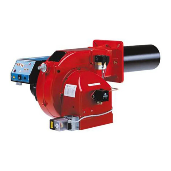
- Page 1 PG30 - PG60 PG70 - PG81 Double-stage Light oil Burners MANUAL OF INSTALLATION - USE - MAINTENANCE BURNERS - BRUCIATORI - BRULERS - BRENNER - QUEMADORES - ГОРЕЛКИ M03965CE Rel. 4.1 03/2010...
-
Page 2: Table Of Contents
TABLE OF CONTENTS WARNINGS ................................3 PART I: INSTALLATION ............................5 GENERAL FEATURES................................... 5 How to interpret the burner’s “Performance curve”......................... 5 Burner model identification ................................5 Technical specifications .................................. 6 Performance curves ..................................7 Overall dimensions ..................................8 MOUNTINGS AND CONNECTIONS .............................. 9 Packing ...................................... -
Page 3: Warnings
WARNINGS THIS MANUAL IS SUPPLIED AS AN INTEGRAL AND ESSENTIAL PART OF THE PRODUCT AND MUST BE DELIVERED TO THE USER. INFORMATION INCLUDED IN THIS SECTION ARE DEDICATED BOTH TO THE USER AND TO PERSONNEL FOLLOWING PRO- DUCT INSTALLATION AND MAINTENANCE. THE USER WILL FIND FURTHER INFORMATION ABOUT OPERATING AND USE RESTRICTIONS, IN THE SECOND SECTION OF THIS MANUAL. - Page 4 DIRECTIVES AND STANDARDS 3b) FIRING WITH GAS, LIGHT OIL OR OTHER FUELS Gas burners GENERAL European directives: The burner shall be installed by qualified personnel and in com- - Directive 90/396/CEE - Gas Appliances; pliance with regulations and provisions in force; wrong installation Directive 2006/95/EC on low voltage;...
-
Page 5: Part I: Installation
Data are referred to standard conditions: atmospheric pressure at 1013mbar, ambient temperature at 15°C Burner model identification Burners are identified by burner type and model. Burner model identification is described as follows. Type PG60 Model PG30-PG60-PG70-PG81 (1) BURNER TYPE G - Light oil A - Biodiesel (2) FUEL... -
Page 6: Technical Specifications
C.I.B. UNIGAS - M03965CE Technical specifications BURNERS PG30 PG60 PG70 PG81 Output min. -max. kW 105 - 383 151 - 791 291 - 1047 264-1900 Fuel Light oil Viscosity cSt @ 40°C 2 - 7.4 Density 0.84 kg/m max. bar... -
Page 7: Performance Curves
C.I.B. UNIGAS - M03965CE Performance curves PG30 PG60 PG70 PG81 800 1000 1200 1400 1600 1800 2000 900 1000 1100 1200 To get the input in kcal/h, multiply value in kW by 860. Data are referred to standard conditions: atmospheric pressure at 1013mbar, ambient temperature at 15°C NOTE: The performance curve is a diagram that represents the burner performance in the type approval phase or in the laboratory tests, but does not represent the regulation range of the machine. -
Page 8: Overall Dimensions
Overall dimensions (mm) PG30 PG60 1042 PG70 1145 PG81 1025 1175 *B, C = measure referred to burner fitted with standard blast tube *BL, CL = measure referred to burner fitted with extended blast tube... -
Page 9: Mountings And Connections
Packing The burners are dispatched in wooden packages whose dimensions are: PG30: 1000 x 550 x 460 mm (L x P x H) PG60: 1200 x 670 x 540 mm (L x P x H) PG70-PG81: 1280 x 850 x 760 mm (L x P x H) Packing cases of this kind are affected by humidity and are not suitable for stacking. -
Page 10: Hydraulic Diagrams For Light Oil Supplying Circuits
C.I.B. UNIGAS - M03965CE Hydraulic diagrams for light oil supplying circuits Fig. 2 - Gravity circuit Fig. 3 - Ring circuit Fig. 4 - Suction circuit Manual valve Light oil filter Light oil feeding pump One way valve Flexible hoses Relief valve NOTE: in plants where gravity or ring feed systems are provided, install an automatic interception device (see n. -
Page 11: Installation Diagram Of Light Oil Pipes
To change from a 1-pipe system to a 2-pipe-system, insert the by-pass plug G (as for ccw-rotation- referring to the pump shaft). Caution: Changing the direction of rotation, all connections on top and side are reversed. PG30: Suntec AS57 PG60: Suntec AN67... -
Page 12: Sizing The Pipeline
C.I.B. UNIGAS - M03965CE Bleed Bleeding in two-pipe operation is automatic: it is assured by a bleed flat on the piston. In one-pipe operation, the plug of a pressure gauge port must be loosened until the air is evacuated from the system. Sizing the pipeline ISyphon twin pipe feed Twin pipe suction feed... -
Page 13: Connecting The Light Oil Flexible Hoses
C.I.B. UNIGAS - M03965CE tank, thus avoiding the possibility that they might be sucked into the pump. On initial commissioning a "dry" operation is foreseen for a considerable length of time (for example, when there is a long suction line to bleed). To avoid damages inject some lubrication oil into the vacuum inlet. Care must be taken when installing the pump not to force the pump shaft along its axis or laterally to avoid excessive wear on the joint, noise and overloading the gears. -
Page 14: Light Oil Pumps
C.I.B. UNIGAS - M03965CE Light oil pumps The pumps provided with these burners can be: PG30: Suntec AS57 PG60: Suntec AN67 PG70: Suntec AJ6 PG81: Suntec J6 Suntec AS57 C Oil viscosity 2 - 12 cSt Oil temperature 0 - 60°C Max. -
Page 15: Electrical Connections
IMPORTANT: while connecting electric supply wires to burner’s teminal block be sure that ground wire should be longer than phase and neutral ones. Burners PG70 - PG81 Burners PG30 - PG60 - PG70 - PG81 not fitted with printed circuit fitted with printed circuit... -
Page 16: Adjustments
C.I.B. UNIGAS - M03965CE ADJUSTMENTS ATTENTION: before starting the burner up, be sure that the manual cutoff valves are open. Be sure that the mains switch is closed. Before starting up the burner, make sure that the return pipe to the tank is not obstructed. Any obstruction would cause the pump seal to break. - Page 17 C.I.B. UNIGAS - M03965CE Choosing the light oil nozzles PUMP PRESSURE (bar) OUTPUT I° NOZZLE II° NOZZLE I° NOZZLE II° NOZZLE I° NOZZLE (kW) (kCal/h) (kg/h) II° NOZZLE G.P.H. G.P.H. G.P.H. G.P.H. G.P.H. G.P.H. 86.000 0,85 1,25 0,80 1,20 0,75 1,10 103.200 10,1...
- Page 18 C.I.B. UNIGAS - M03965CE Oil nozzle flow rates PUMP PRESSURE (bar) NOZZLE NOZZLE G.P.H. G.P.H. (kg/h) 0,30 0,30 0,35 0,35 0,40 0,40 0,45 0,45 0,50 0,50 0,55 0,55 0,60 0,60 0,65 0,65 0,70 0,70 0,75 0,75 0,80 0,80 0,85 0,85 0,90 0,90 1,00...
-
Page 19: Priming The Pump And Adjustments
Check that the combustion parameters are in the suggested limits. Priming the pump and adjustments PG30 Before carrying out the adjustment it is necessary to start up the fuel pump, proceeding as follows: remove the electric panel cover;... - Page 20 C.I.B. UNIGAS - M03965CE means of a screwdriver, by twisting the VS screw located inside the cam. Siemens SQN72: a key is provided to move cams I and IV, the other cams can be moved by means of screws. On the Siemens actuator the AUTO/MAN mode is provided (see picture).
-
Page 21: Adjustments For Burners With Hydraulic Ram
C.I.B. UNIGAS - M03965CE means of the cam lever Siemens SQN72: a key is provided to move cams I and IV, the other cams can be moved by means of screws. On the Siemens actuator the AUTO/MAN mode is provided (see picture). 10 by removing the bridge between the 6 and 7 terminals of the TAB thermostat , the actuator moves to the position (degrees) set for the ST1 cam (low flame cam);... -
Page 22: Adjusting The Combustion Head
C.I.B. UNIGAS - M03965CE Adjusting the combustion head To let the burner operate at a lower output, turn clockwise the VRT screw and move progressively the combustion head back towards the MIN position. ”MAX” position ”MIN” position Note: loosen VB screw to free the VRT screw; adjust the head and then remember to fasten VB again. Attention! if it is necessary to change the head position, repeat the air and gas adjustments described above. -
Page 23: Part Ii: Operation
C.I.B. UNIGAS - M03965CE PART II: OPERATION LIMITATIONS OF USE THE BURNER IS AN APPLIANCE DESIGNED AND CONSTRUCTED TO OPERATE ONLY AFTER BEING CORRECTLY CON- NECTED TO A HEAT GENERATOR (E.G. BOILER, HOT AIR GENERATOR, FURNACE, ETC.), ANY OTHER USE IS TO BE CONSI- DERED IMPROPER AND THEREFORE DANGEROUS. - Page 24 Signalling light of the opening of 1st stage solenoid valve Signalling light of the opening of 2nd stage solenoid valve High flame operation signalling light Low flame operation signalling light Ignition transformer in operation signalling light Overload tripped signalling light ( PG30 excluded)
-
Page 25: Part Iii: Maintenance
C.I.B. UNIGAS - M03965CE PART III: MAINTENANCE At least once a year carry out the maintenance operations listed below. In the case of seasonal servicing, it is recommended to carry out the maintenance at the end of each heating season; in the case of continuous operation the maintenance is carried out every 6 months. -
Page 26: Correct Position Of Electrodes And Combustion Head
C.I.B. UNIGAS - M03965CE Correct position of electrodes and combustion head Fig. 15 ATTENTION: avoid the electrodes to get in touch with metallic parts (blast tube, head, etc.), otherwise the boiler operation would be compromised. Check the electrodes position after any intervention on the combustion head. To guarantee a good ignition the measures showed on the next picture Fig. -
Page 27: Replacing The Ignition Electrodes
C.I.B. UNIGAS - M03965CE Replacing the ignition electrodes ATTENTION: avoid the electrodes to get in touch with metallic parts (blast tube, head, etc.), otherwise the boiler operation would be compromised. Check the electrodes position after any intervention on the combustion head. To replace the ignition electrodes, proceed as follows: remove the burner cover;... -
Page 28: Troubleshooting
C.I.B. UNIGAS - M03965CE TROUBLESHOOTING MAIN SWITCH OPEN LINE FUSE INTERVENTION MAX. PRESSURE SWITCH FAULT FAN THERMAL CUTOUT INTERVENTION AUXILIARY RELAIS FUSES INTERVENTION CONTROL BOX FAULT ACTUATOR FAULT SMOKEY FLAME IGNITION TRANSFORMER FAULT IGNITION ELECTRODE DIRTY OR WRONG POSITIONED DIRTY NOZZLE FUEL SOLENOID VALVE DEFECTIVE PHOTORESISTOR DIRTY OR DEFECTIVE HI-LO FLAME THERMOSTAT DEFECTIVE... -
Page 29: Spare Parts
C.I.B. UNIGAS - M03965CE SPARE PARTS Desription Code PG30 PG60 PG70 PG81 LOA24: 2020445 LOA24: 2020445 LMO44: 2020455 LMO44: 2020455 CONTROL BOX LMO24: 2020453 LMO24: 2020453 2080205 2080205 2080205 2080205 IGNITION ELECTRODES 2080206 2080206 2080206 2080206 LONG IGNITION ELECTRODES 2090025... -
Page 30: Electrical Wiring Diagrams
C.I.B. UNIGAS - M03965CE ELECTRICAL WIRING DIAGRAMS Wiring diagram 07-348 Fan motor contactor coil Fan motor thermal cutout terminals Fan motor contactor terminals EVG1 Solenoid valve 1st stage EVG2 Solenoid valve 2nd stage Fuses Photoresistor Main switch Auxiliaries line switch Phase Burner in high flame signaling lamp Flame lockout signaling lamp... - Page 35 C.I.B. UNIGAS - M03965CE Wiring diagram 18-141 Fan motor contactor coil Connector for triphase version Fan motor thermal cutout terminals Fan motor contactor terminals EVG1 Solenoid valve 1st stage EVG2 Solenoid valve 2nd stage F-FU Fuses (FU=6,3A triphase versions - FU=10A monophase versions) FILTRO Line noise filter (optional) Connector on electrical board front panel...
-
Page 38: Appendix
APPENDIX The multicolour «LED» is the key indicating element for both visual diagnosis and interface diagnosis. SIEMENS OIL BURNERS AUTOMATIC CONTROLLER SIEMENS LMO14 - LMO24 - LMO44 The LMO... burner controls are designed for the start-up and supervision of single- or 2-stage forced draught oil burners in intermittent operation. Yellow-burning flames are supervised with photoresistive detectors Yellow QRB..., blue-burning flames with blue-flame detectors QRC... - Page 39 LMO14 LMO24 - LMO44 A ´ μC control μC1 μC2 t 3n t 3n t 3n 7130a01e/0700 LMO24 - LMO44 7130d03e/ 0700 µC cont r ol µC 1 µC 2 Alarm device kbr... Cable link (required only when no oil pre-heater is used) BV...
- Page 40 2 supplementary terminals numbered “31” and “32”. General unit data The socket has two openings at the bottom for the leads; 5 others with Mains voltage AC 230 V +10 % / -15 % threaded connection for cable holders PG11 or 3/4UNP for non-metallic AC 120 V +10 % / -15 % sleeves are located on a mobile stuffing box, one on either side and 3 on Mains frequency...
- Page 41 To tamper with them in any way may have unforeseeable conse- Terminal flow: quences! terminals 4, 5 &10 terminals 6&7 Do not open them! terminal 8 Absorbed cap Protection IP40 Premitted temp: operational -20...+60°C transport & storage -50...+60°C Emplacement Mass (weight) controller 180g, socket 50g, AGK accessories 12 g.
- Page 44 C.I.B. UNIGAS S.p.A. Via L.Galvani, 9 - 35011 Campodarsego (PD) - ITALY Tel. +39 049 9200944 - Fax +39 049 9200945/9201269 web site: www.cibunigas.it - e-mail: cibunigas@cibunigas.it Note: Specifications and and data subject to change. Errors and omissions excepted.
Need help?
Do you have a question about the PG30 and is the answer not in the manual?
Questions and answers