
Subscribe to Our Youtube Channel
Related Manuals for CIB UNIGAS KP91


Summary of Contents for CIB UNIGAS KP91
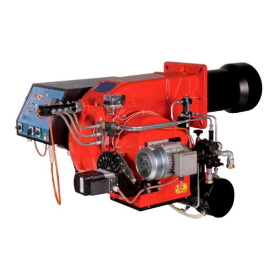
- Page 1 KP91 KP92 KP93 KR512 KR515 KR520 KR525 Gas - heavy oil burners MANUAL OF INSTALLATION - USE - MAINTENANCE BURNERS - BRUCIATORI - BRULERS - BRENNER - QUEMADORES - ГОРЕЛКИ M03940CL 0.0 06/2020...
-
Page 2: General Introduction
DANGERS, WARNINGS AND NOTES OF CAUTION THIS MANUAL IS SUPPLIED AS AN INTEGRAL AND ESSENTIAL PART OF THE PRODUCT AND MUST BE DELIVERED TO THE USER. INFORMATION INCLUDED IN THIS SECTION ARE DEDICATED BOTH TO THE USER AND TO PERSONNEL FOLLOWING PRODUCT INSTALLATION AND MAINTENANCE. -
Page 3: Directives And Standards
3b) FIRING WITH GAS, LIGHT OIL OR OTHER FUELS DIRECTIVES AND STANDARDS Gas burners GENERAL European directives The burner shall be installed by qualified personnel and in compliance -Regulation 2016/426/UE (appliances burning gaseous fuels) with regulations and provisions in force; wrong installation can cause -2014/35/UE (Low Tension Directive) injuries to people and animals, or damage to property, for which the -2014/30/UE (Electromagnetic compatibility Directive) -
Page 4: Symbols Used
Burner data plate Type Gas - Light oil burners For the following information, please refer to Model Year European Directives the data plate: S.Number -Regulation 2016/426/UE (appliances burning gaseous fuels) burner type and burner model: must be Output Oil Flow -2014/35/UE (Low Tension Directive) reported in any communication with the Fuel... -
Page 5: Burner Features
KR525 Model MD. S. (1) BURNER TYPE KP91 - KP92 - KP93 - KR512 - KR515 - KR520 - KR525 M - Natural gas, L - LPG E - Heavy oil, viscosity <= 110cSt (15°E) @ 50° C (2) FUEL D - Heavy oil, viscosity <= 400cSt (50°... - Page 6 PART I: SPECIFICATIONS BURNERS KP91 KP92 KP93 Output min. - max. kW 480 - 2670 480-3050 550 - 4100 Natural gasHeavy oil Fuel Category (see next paragraph) min. - max. (Stm 51 - 283 51 - 323 58 - 434 Gas rate min.
- Page 7 PART I: SPECIFICATIONS BURNERS KP91 L- KP92 L- KP93 L- Output min. - max. kW 480 - 2670 480-3050 550 - 4100 LD - L LPG - D Heavy oil, viscosity <= 400cSt (50° E) @ 50° C Fuel Category...
- Page 8 PART I: SPECIFICATIONS Country and usefulness gas categories COUNTRY CATEGORY ES GR SE NO CZ DK GB PT CY EE LV MT SK BG LT RO TR CH 2E( R ) B (*) I 2ELL (*) Only for I : the appliance was configured for the appliance category K (I2K) and is suitable for the use of G and G+ distribution gases according to the specifications as included in the NTA 8837:2012 Annex D with a Wobbe index of 43.46 –...
- Page 9 Overall dimensions (mm) KP91, KP92, KP93 Boiler recommended drilling template O min. O max. Reccomended burner flange 50 1615 152 221 473 429 100 560 441 1055 533 1455 464 859 441 596 304 344 228 329 360 466 M12 424 280 310 300 522 148 374...
- Page 10 KR512 Boiler recommended drilling template O min-max Reccomended burner flange AA AD AE AN AP 50 1766 229 35 313 594 100 555 508 1211 598 1585 407 943 476 642 380 420 354 540 560 M14 552 390 390 755 150 605 843 216 891 328 270 65 1766 229 35 313 612 118 555 508 1119 598 1609 407 967 476 642 380 420 354 540 560 M14 552 390 390 633 150 483 843 292 891 328 270 KR512 80 1766 229 35 313 626 132 555 508 1119 598 1644 407 1002 476 642 380 420 354 540 560 M14 552 390 390 685 150 535 875 322 891 328 270...
- Page 11 KR515, KR520 Boiler recommended drilling template O min-max Reccomended burner flange 1676 144 508 1146 598 1585 943 492 M14 552 1676 144 508 1146 598 1609 967 492 M14 552 1676 144 508 1146 598 1644 1002 642 492 M14 552 100 1676 144 508 1146 598 1727 1085 642 492 M14 552...
- Page 12 KR525 O min-max Reccomended burner flange Boiler recommended drilling template AA AD AN 1682 144 35 594 100 530 650 1152 598 1585 642 454 504 494 540 492 M14 552 390 390 755 150 605 843 216 759 343 270 1682 144 35 612 118 530 650 1152 598 1609 642 454 504 494 540 492 M14 552 390 390 633 150 483 843 292 759 343 270 1682 144 35 626 132 530 650 1152 598 1644 1002 642 454 504 494 540 492 M14 552 390 390 685 150 535 875 322 759 343 270...
- Page 13 KP91, KP92, KP93, KR512 Fig. 4 3I2MD11 v1 Hydraulic diagram BY OTHERS BY BURNER CONSTRUCTOR oil inlet oil outlet gas inlet combustion air inlet ATTENTION: connect the oil return line to the degassing bottle (standard UNI 9248), as shown in the chapter "Recommendations to design heavy oil feeding plants"...
- Page 14 KR515, KR520, KR525 Fig. 5 3I2MD15 v1 Hydraulic diagram BY OTHERS preassembling unit on a self standing skid BY BURNER CONSTRUCTOR oil inlet oil outlet gas inlet combustion air inlet ATTENTION: connect the oil return line to the degassing bottle (standard UNI 9248), as shown in the chapter "Recommendations to design heavy oil feeding plants"...
- Page 15 PART I: SPECIFICATIONS How to read the burner “Performance curve” To check if the burner is suitable for the boiler to which it must be instal- Campo di lavoro bruciatori lled, the following parameters are needed: Tipo P60 Mod. M-xx.x.IT.A.0.50 - M-.xx.x.IT.A.0.65 furnace input, in kW or kcal/h (kW = kcal/h/860);...
-
Page 16: Performance Curves
PART I: SPECIFICATIONS Performance Curves KP91 KP92 1200 1600 2000 2400 2800 3200 3600 KP93 1500 2500 3500 4500 KR512 KR515 1500 2500 3500 4500 5500 1500 2500 3500 4500 KR520 KR525 1500 2500 3500 4500 5500 6500 7500 1500... - Page 17 PART I: SPECIFICATIONS Pressure in the network - gas rate curves - natural gas KP91 KP92 Rp 2" (50) DN65 DN80 DN100 KP93 Rp 2" (50) DN65 DN80 DN100 KR512 KR515 Rp 2" (50) Rp 2" (50) DN65 DN65 DN80...
- Page 18 PART I: SPECIFICATIONS Combustion head gas pressure curves Combustion head gas pressure depends on gas flow and combustion chamber backpressure. When backpressure is subtracted, i depends only on gas flow, provided combustion is properly adjusted, flue gases residual O2 percentage complies with “Recommended combustion values”...
- Page 19 Pressure - rate in combustion head curves (natural gas) PART I: SPECIFICATIONS Curves are referred to pressure = 0mbar in the combustion chamber! KP91 KP92 40 60 80 100 120 140 160 180 200 220 240 260 280 300 320 340...
- Page 20 MOUNTING AND CONNECTING THE BURNER Packing The burners are despatched wooden cages whose dimensions: KP91-KP92-KP93: 1730mmx 1280mm x 1020mm (L x P x H) KR512-KR515-KR520-KR525: 1730mm x 1430mm x 1130mm (L x P x H) Packing cases of this kind are affected by humidity and are not suitable for stacking. The following are placed in each packing case: burner with gas train detached;...
- Page 21 PART II: INSTALLATION Fitting the burner to the boiler To install the burner into the boiler, proceed as follows: make a hole on the closing door of the combustion chamber as described on paragraph “Overall dimensions”) place the burner to the boiler: lift it up and handle it according to the procedure described on paragraph “Handling the burner”; place the 4 stud bolts (5) on boiler’s door, according to the burner drilling template described on paragraph “Overall dimensions”;...
- Page 22 PART II: INSTALLATION GAS TRAIN CONNECTIONS The diagrams show the components of the gas train included in the delivery and which must be fitted by the installer.The diagrams are in compliance with the current laws. Note: the figure is indicative only ”direction”...
- Page 23 PART II: INSTALLATION MultiBloc MBE ALLA V. FARFALLA Example of gas train MBE 501939 GAS BRUCIATORE ø185 VD-R VD-V VD-R VD-V Gas filter PGMAX PGMAX PGMI PGMIN PS pressure sensor PGCP PGCP ATTENTION: once the gas train is mounted according, the gas proving test mus be performed, according to the procedure set by the laws in force.
- Page 24 PART II: INSTALLATION Mounting VD-R & PS-... ActuatorVD-V ActuatorVD-R M12 x 5 Pin The actuator VD-V does not need any adjustment (funzione ON-OFF) The actuator VD-R It must be combined with the PS sensor (include regolatore di pressione) VD-R + PS 1.
- Page 25 PART II: INSTALLATION SIEMENS VGD.. SKP1. SKP2. Mounting positions = BS PGMAX PGCP PGMIN Siemens VGD... con SKPx Example of gas train Gas filter version with SKP2 (built-in pressure stabilizer) Siemens VGD valves with SKP actuator: The pressure adjusting range, upstream the gas valves group, changes according to the spring provided with the valve group.
- Page 26 PART II: INSTALLATION Once the train is installed, connect the gas valves group and pressure switches plugs. OIL TRAIN CONNECTIONS About the use of fuel pumps Do not use fuel with additives to avoid the possible formation over time of compounds which may deposit between the gear teeth, ...
- Page 27 PART II: INSTALLATION Rotation speed 3600 rpm max. 1. Connection for manometer 1 – delivery (M1) – G1/4 2. Connection for manometer 2 – suction (M2) – G1/4 3. Connection for manometer 3 (M3) A. Suction connection– G1/2 D. Direct - clockwise I.
- Page 28 Connecting the burner to the oil pumping unit PART II: INSTALLATION KR515, KR520, KR525 G1/2” G1/2” G3/4” Legend inlet return G1” G3/8” G1”...
- Page 29 PART II: INSTALLATION PLANT WITH DEGASING BOTTLE KP91, KP92, KP93, KR512 Legend inlet G1/2” G1” G1” G1/2” G1/2” G1” KR515, KR520, KR525 G1/2” G1/2” Legend inlet return G3/4” G1” G1/2” G1” G1/2” G1/2” G1”...
-
Page 30: Electrical Connections
PART II: INSTALLATION ELECTRICAL CONNECTIONS WARNING! Respect the basic safety rules. make sure of the connection to the earthing system. do not reverse the phase and neutral connections. fit a differential thermal magnet switch adequate for connection to the mains. WARNING! before executing the electrical connections, pay attention to turn the plant’s switch to OFF and be sure that the burner’s main switch is in 0 position (OFF) too. - Page 31 PART II: INSTALLATION ELECTRIC MOTOR CONNECTION 400 V 230V Connecting the oil heating resistors 2.4 - 4.5 kW 8 - 12 kW 400 V 230V 400 V 230V Fig. 4 Fig. 5 18 - 24 kW 400 V 230V Fig. 6...
- Page 32 PART II: INSTALLATION RECOMMENDATIONS TO DESIGN HEAVY OIL FEEDING PLANTS This paragraph is intended to give some suggestions to make feeding plants for heavy oil burners. To get a regular burner operation, it is very important to design the supplying system properly. Here some suggestions will be mentioned to give a brief description. The term “heavy oil”...
- Page 33 PART II: INSTALLATION Viscosity units conversion table Saybolt Cinematics Saybolt Redwood Engler Degrees Seconds Redwood Seconds viscosity Seconds Seconds no.1 (°E) Universal no..2 (Admiralty) Centistokes (cSt) Furol (SSF) (Standard) (SSU) 2.56 1.16 32.1 1.31 36.2 1.58 44.3 5.83 10.3 1.88 52.3 6.77 13.1...
- Page 34 PART II: INSTALLATION VISCOSITY vs TEMPERATURE DIAGRAM FOR COMBUSTIBLE OILS 1000 PUMPING LIMIT TEMPERATURE (°C) LIGHT OIL 1,3°E AT 20°C HEAVY OIL 2,4°E AT 50°C HEAVY OIL 4°E AT 50°C HEAVY OIL 7,5°E AT 50°C HEAVY OIL 10°E AT 50°C HEAVY OIL 13°E AT 50°C HEAVY OIL 22°E AT 50°C HEAVY OIL 50°C...
- Page 35 PART II: INSTALLATION Indicative diagram showing the oil temperature at burner pump inlet vs. oil viscosity Example: if the oil has a 50°E @ 50°C viscosity, the oil temperature at the pump inlet should be 80°C (see diagram). OIL TEMPERATURE FOR PUMP FEEDING TEMPERATURE (°C) Fig.
- Page 36 Fig. 11 3ID00014 v2 Hydraulic diagram - Two or more burners configuration BURNER 2 SEE THE BURNER 1 SEE THE BURNER P&ID BURNER P&ID HEATING MEDIUM INLET HEATING MEDIUM OUTLET PRESSURE GOVERNOR UNIT OIL PUMPING UNIT DAILY TANK UNIT OIL PUMPING UNIT PIPE HEATING SYSTEM: SEE THE SPECIFIC HEATING MEDIUM INLET MAIN TANK INLET...
- Page 37 Fig. 12 - 3ID0023 v2 - Hydraulic diagram - Single burner configuration BURNER 1 SEE THE BURNER P&ID OIL TRAIN Main tank OIL PUMPING UNIT Manual valve Filter Pump coupled to electrical motor Safety valve HEATING MEDIUM INLET One-way valve Manual valve HEATING MEDIUM OUTLET Pressure gauge...
-
Page 38: Limitations Of Use
PART III: OPERATION PART III: OPERATION DANGER! Incorrect motor rotation can seriously damage property and injure people.WARNING: before starting the burner up, be sure that the manual cutoff valves are open and check that the pressure upstream the gas train complies the value quoted on paragraph “Technical specifications”. -
Page 39: Gas Operation
PART III: OPERATION Funzione MIX MATIC The terminal block MA inside the switch cabinet has 2 ter- Position 0: burner off minals: Position 1: burner operation 1st fuel 14A and 15A to which the dry contact is connected. Position 2: burner operation 2nd fuel NO contact: 1st fuel burner operationКонтакт... - Page 40 PART III: OPERATION AIR FLOW AND FUEL ADJUSTMENT WARNING! During commissioning operations, do not let the burner operate with insufficient air flow (danger of formation of carbon monoxide); if this should happen, make the fuel decrease slowly until the normal combustion values are achieved.
-
Page 41: Pressure Taps
PART III: OPERATION MultiBloc MBE Regulation VD-R whith PS Setting scale is „Not“ linear! Various sensors available. Output pressure according to sensor‘s measuring range. Increasing pressure Adjust the outlet pressure to the value specified by the burner or equipment manufacturer! While making outlet pressure adjustments, do not exceed a value that creates a hazardous condition to the burner! - Page 42 PART III: OPERATION shaft the air damper closes and the air flow rate decreases. Note: once the procedure is perfomed, be sure that the blocking nut RA is fasten. Do not change the position of the air dam- per rods. If necessary, adjust the combustion head position (see the dedicated paragraph).
- Page 43 PART III: OPERATION pressure is reduced by 50%. Pay attention that the CO value in the flue gas does not increase: if the CO values are higher than the limits laid down by law, slowly open the cutoff valve as to get values lower than these limits. Check that the burner is operating correctly.
- Page 44 Adjusting the combustion head PART III: OPERATION Only if necessary, change the combusiton head position: to let the burner operate at a lower output, loose the VB screw and move pro- gressively back the combustion head towards the MIN position, by turning clockwise the VRT ring nut. Fasten VB screw when the adjustment is accomplished.
- Page 45 ADJUSTMENTS FOR OIL OPERATION PART III: OPERATION Before starting up the burner, make sure that the return pipe to the tank is not obstructed. Any obstruction would cause the pump seal to break. ATTENTION: before starting the burner up, be sure that the manual cutoff valves are open. Be sure that the mains switch is closed.
- Page 46 PART III: OPERATION Oil viscosity at 50 °C according to the letter shown in the burner model Menu path > 50 cSt > 110 cSt > 400 cSt 89 cSt < 50 cSt < 110 cSt < 400 cSt < 4000 cSt >...
- Page 47 Adjusting heavy oil flow rate PART III: OPERATION The oil flow rate can be adjusted choosing a nozzle that suits the boiler/utilisation output and setting the delivery and return pressure values according to the ones quoted on the following charts. DELIVERY NOZZLE PRESSURE...
- Page 48 PART III: OPERATION Oil Flow Rate Settings by means of Siemens SQM40.. Once the air and gas flow rates are adjusted, turn the burner off, switch to the oil operation (OIL, on the burner control panel). with the electrical panel open, prime the oil pump acting directly on the related CP contactor (see next picture): check the pump motor rotation and keep pressing for some seconds until the oil circuit is charged;...
- Page 49 PART III: OPERATION Pressure gauge port Pressure gauge port...
- Page 50 PART IV: MAINTENANCE PART IV: MAINTENANCE At least once a year carry out the maintenance operations listed below. In the case of seasonal servicing, it is recommended to carry out the maintenance at the end of each heating season; in the case of continuous operation the maintenance is carried out every 6 months.
- Page 51 PART IV: MAINTENANCE MultiBloc MBE MultiBloc VD Mounting to push position 1. Position VD on VB, fig. 2+3. 2. Slide VD forward up to the stop, fig. 4. 3. Screw VD on with 2 M5 screws for each, max. 5 Nm/44 in.-lb., fig. 5/6. 4.
-
Page 52: Self-Cleaning Filter
PART IV: MAINTENANCE Thecnical procedure of self cleaning filters substitution (valid for all models) 1 Close the bowl valve before the self cleaning filter 2 Switch off any electrical equipment on board on the filter (example motorization or heaters) WARNING! Drain the system by unscrewing the drain screw on the bottom of the self cleaning filter 3 Disconnect the outlet pipe from the cover of the self cleaning filter 4 Remove the cover with all the filter pack, leaving only the bowl on the line 5 Clean any residue on the bottom of the bowl and clean the seat of the O-ring seal... - Page 53 PART IV: MAINTENANCE Removing the oil gun, replacing the nozzle and the electrodes ATTENTION: avoid the electrodes to get in touch with metallic parts (blast tube, head, etc.), otherwise the boiler operation would be compromised. Check the electrodes position after any intervention on the combustion head. To remove the oil gun, proceed as follows: remove the combustion head as described on the prevoius paragraph;...
-
Page 54: Seasonal Stop
PART IV: MAINTENANCE Checking the detection current To check the detection signal follow the scheme in the picture below. If the signal is less than the value indicated, check the position of the detection electrode or detector, the electrical contacts and, if necessary, replace the electrode or the detector. TERMINAL BOARD Control box Minimum detection signal... - Page 55 PART IV: MAINTENANCE TROUBLESHOOTNG GUIDE Gas operation * No electric power supply * Restore power supply * Main switch open * Close switch * Thermostats open * Check set points and thermostat connections * Bad thermostat set point or broken thermostat * Reset or replace the thermostat * No gas pressure * Restore gas pressure...
- Page 56 KP91, KP92, KP93 17.3 14 26.1 22.1 22.2 23.3 23.2 23.4 23.1 26.2 17.1 16.2 17.2 27.1 16.1.1 27.7 22.3 20.6 16.3 18.2 27.4 20.3 20.9 21.2 27.3 27.5 26.5 26.6 27.6 26.3 26.4 28.2 16.1 27.5 19.3 18.3 20.1 20.4...
- Page 57 AIR INLET CONE 20.2 AIR INTAKE DAMPER 27.7 COMBUSTION HEAD GAS BLEEDING VALVE 20.3 AIR INTAKE 28.1 BOARD OIL FLEXIBLE HOSE 20.4 LOUVER SHAFT 28.2 COVER OIL FLEXIBLE HOSE 20.5 LOUVER SHAFT 29.1 CONTROL BOX OIL FLEXIBLE HOSE 20.7 ADJUSTING CAM SHAFT 29.2 CONTROL BOX SOCKET PLATE...
- Page 58 APPENDIX SIEMENS LFL 1.3.. CONTROL BOX consent to start-up by means of the thermostat or pressostat "R" start-up program Automatic programme in the event of interruption and indication of posi- tion when interrupted normal burner operation By default, in the event of any kind of interruption, the flow of fuel is imme- regulation stop caused by "R"...
- Page 59 Ionisation monitor Twin-tube burners (**) voltage in detector electrode Preignition time until the all clear to the pilot burner valve at normal working 330V ±10% terminal 17. test 380V ±10% First safety time (pilot flame strenght); at the end of the safety time short circuit current max.
- Page 60 Programmer diagram pre-ventilation time limit contact switch for damper OPEN position safety time block remote signal '1st safety time main relay (working network) with contacts "ar" pre-ignition time Monitor fuse 'pre-ignition time block relay with "br" contacts interval for creating current between terminals 18 and 19 fuel valve 'interval for creating current between terminals 17 and 19 reset button...
- Page 64 C.I.B. UNIGAS S.p.A. Via L.Galvani, 9 - 35011 Campodarsego (PD) - ITALY Tel. +39 049 9200944 - Fax +39 049 9200945/9201269 web site: www.cibunigas.it - e-mail: cibunigas@cibunigas.it Note: specifications and data subject to change. Errors and omissions excepted.
-
Page 65: Technical Specifications
CIB UNIGAS 600V CONTROLLER USER’S MANUAL COD. M12925CA Rel 1.2 08/2014 SOFTWARE VERSION 1.0x code 80379 / Edition 01 - 06/2012 1 • INSTALLATION 2 • TECHNICAL SPECIFICATIONS Display 2x4 digit green, high display 10 and 7mm Keys 4 of mechanical type (Man/Aut, INC, DEC, F) •... - Page 66 3 • DESCRIPTION OF FACEPLATE Function indicators Indication of output states Indicates modes of operation OUT 1 (AL1); OUT 2 (OPEN); OUT 3 (CLOSED) MAN/AUTO = OFF (automatic control) ON (manual control) PV Display: Indication of process variable Error Indication: LO, HI, Sbr, Err PRE-HEATING = ON (running) LO= the value of process variable is <...
-
Page 67: Programming And Configuration
5 • “EASY” PROGRAMMING and CONFIGURATION S4 Jumper THE EASY CONFIGURATION (Pro=0...12) IS SUITABLE FOR (CPU) VERSIONS WITH AL1/OPEN/CLOSED LEVEL 1 MENU P.V. / S.V. Process variable P.V. / S.V. (PV display) Work Setpoint (SV display) or control output value with controller in manual Password Local Setpoint... - Page 68 • InFo Display Information display Software version 0 No Error Self diagnostic 1 Lo error code 2 Hi 3 ERR 4 SBR OUTPUT 2 OUTPUT 3 SERIAL COMMUNICATION 0 = None 0 = None 0 = None +8 error OUT2 card recognition 1 = Relay 1 = Relay +16 error OUT3 card recognition...
- Page 69 • InP Input settings S, R range 0...1750°C; error < 0.2% f.s. (t > 300°C) / for other sp. r 0 default (remote setpoint present) Def. remote setpoint range; error < 0.5% f.s. error < 0.2% f.s. (t > -150°C) range 44...1800°C;...
- Page 70 • Out Output settings Select a1. r reference signal for alarm1 AL.1.r AL.x.r Variable to be compared PV (process variable) AL.1.t AL.x.t Direct (high limit) Absolute or Normal 2/3 for a1. t Inverse (low limit) relative to Symmetrical alarm 1 active setpoint (window) direct...
- Page 71 • Prot Protection code Prot Display Modification SP, Hy.P, Hy.n, AL.2, AL.3, PoS, OuP, INF SP, Hy.P , Hy.n, AL.2, AL.3, PoS SP, Hy.P, Hy.n, AL.2, AL.3, PoS, OuP, INF SP, OuP, INF + 4 to disable InP, Out + 8 to disable CFG + 16 to disable SW “power-up - power down”...
- Page 72 ld. 1 Function of LEDs Val. Function none MAN/AUTO controller ld. 2 HOLD Selftuning enabled Autotuning enabled ld. 3 Error present Softstart running Set point gradient running Pre-heating running + 16 LED flashes if active • Lin Custom linearization for main input Step 0 beginning Display limits s.
-
Page 73: Pre-Heating Function
7 • CONSENT FOR BURNER AL1 Obtain burner consent by configuring alarm 1 as inverse deviation with positive hysteresis Hy.P and negative hysteresis Hy.n 8 • PRE-HEATING FUNCTION Enable the pre-heating function by setting parameters GS.0, Ht.0, GS.1 other than zero. It consists of three phases that are activated sequentially at firing: - Ramp 0 phase Enabled by setting GS.0 >... - Page 74 9 • ADJUSTMENT WITH MOTORIZED VALVE In an adjustment process the adjustment valve has the function of varying fuel delivery (frequently corresponding to the thermal energy introduced into the process) in relation to the signal coming from the controller. For this purpose it is provided with an actuator able to modify its opening value, overcoming the resistances produced by the fluid passing inside it.
-
Page 75: Control Actions
Valve control modes With the controller in manual, the setting of parameter At.y ≥ 8 allows direct control of the valve open and close commands through the keyboard Increments and Decrements on the front seats. V0 - for floating valve without potentiometer Model V0 have similar behaviour: every manoeuvre request greater than the minimum impulse t.Lo is sent to the actuator by means of the OPEN/CLOSE relays;... -
Page 76: Manual Tuning
11 • MANUAL TUNING A) Enter the setpoint at its working value. B) Set the proportional band at 0.1% (with on-off type setting). C) Switch to automatic and observe the behavior of the variable. It will be similar to that in the figure: Process D) The PID parameters are calculated s follows: Proportional band Variable... -
Page 77: Order Code
15 • ACCESSORIES • Interface for instrument configuration Kit for PC via the USB port (Windows environment) for GEFRAN instruments configuration: KIT PC USB / RS485 o TTL Lets you read or write all of the parameters • A single software for all models •... - Page 79 21/06/2012 rev. 0 Set-up for 600V RRR0-1-T73 regulator Set up for temperature probe Pt100 (ex Siemens QAE2120 130°C max.) The regulator comes out of the factory preset with the corresponding values of the Siemens RWF40.000 and RWF50.2x Verify wiring of the sensor Regulation of the set-point = 80 It can be modified by using arrows "up"...
-
Page 80: Manual Operation
A1.r … A1.t 3 (operating mode AL1 =inverse-relative-normal) … rL.1 2 (AL1) rL.2 18 (open) rL.3 19 (close) A.ty 9 (type of servocontrol command) Ac.t 12 (servocontrol running time: SQN72.4…/STA12..=12; SQM40.265=30) t_Lo t_Hi t.on t.oF dE.b 0,1 (dead zone in % of end scale) 99 then push and keep pushed F until visualization of Hrd …... - Page 81 Set up for temperature probe Pt100 for high temperature (350°C max.) Verify wiring of the sensor Regulation of the set-point = 80 It can be modified by using arrows "up" and "down". By pushing F you go to parameters: Hy.P 10 (hysteresis positive for output 1 terminals 21-22 (ex Q13-Q14) Hy.n -5 (hysteresis negative for output 1 terminals 21-22 (ex Q13-Q14)
- Page 82 A1.r … A1.t 3 (mode AL1 =inverse-relative-normal) … rL.1 2 (AL1) rL.2 18 (open) rL.3 19 (close) A.ty 9 (type of servocontrol command) Ac.t 12 (servocontrol running time: SQN72.4…/STA12..=12; SQM40.265=30) t_Lo t_Hi t.on t.oF dE.b 0,1 (dead zone in % of end scale) 99 then push and keep pushed F until visualization of Hrd …...
- Page 83 Set up for pressure transmitter 2 wires signal 4÷20mA With pressure transmitters first we need to enable their power supply: remove the part as shown below, then, on the CPU unit, move the bridge from Pt100 to +Vt IN/OUT cards Signal selection on terminal 3 Verify wiring of the sensor...
- Page 84 …. 44 (4÷20mA) … dP_S 2 (decimals num.) Transmitter 1,6bar 3bar 10bar 16bar 25bar 40bar Lo.S 0,00 0,00 0,00 0,00 0,00 0,00 min. sensor scale Hi.S 1,60 3,00 10,00 16,00 25,00 40,00 max sensor scale offset of input correction Lo.L 0,00 0,00 0,00...
- Page 85 Set -up for thermocouples type Verify wiring of the sensor Regulation of the set-point = 80 It can be modified by using arrows "up" and "down". By pushing F you go to parameters: Hy.P 10 (hysteresis positive for output 1 terminals 21-22 (ex Q13-Q14) Hy.n -5 (hysteresis negative for output 1 terminals 21-22 (ex Q13-Q14) Keep pushing F until you see PASS, release F and through the arrows set 99, push F and visualize Pro...
- Page 86 A1.r … A1.t 3 (mode AL1 =inverse-relative-normal) … rL.1 2 (AL1) rL.2 18 (open) rL.3 19 (close) A.ty 9 (type of servocontrol command) Ac.t 12 (servocontrol running time: SQN72.4…/STA12..=12; SQM40.265=30) t_Lo t_Hi t.on t.oF dE.b 0,1 (dead zone in % of end scale) 99 then push and keep pushed F until visualization of Hrd …...
- Page 89 CIB UNIGAS 600V CONTROLLER USER’S MANUAL COD. M12925CA Rel 1.2 08/2014 SOFTWARE VERSION 1.0x code 80379 / Edition 01 - 06/2012 1 • INSTALLATION 2 • TECHNICAL SPECIFICATIONS Display 2x4 digit green, high display 10 and 7mm Keys 4 of mechanical type (Man/Aut, INC, DEC, F) •...
- Page 90 3 • DESCRIPTION OF FACEPLATE Function indicators Indication of output states Indicates modes of operation OUT 1 (AL1); OUT 2 (OPEN); OUT 3 (CLOSED) MAN/AUTO = OFF (automatic control) ON (manual control) PV Display: Indication of process variable Error Indication: LO, HI, Sbr, Err PRE-HEATING = ON (running) LO= the value of process variable is <...
- Page 91 5 • “EASY” PROGRAMMING and CONFIGURATION S4 Jumper THE EASY CONFIGURATION (Pro=0...12) IS SUITABLE FOR (CPU) VERSIONS WITH AL1/OPEN/CLOSED LEVEL 1 MENU P.V. / S.V. Process variable P.V. / S.V. (PV display) Work Setpoint (SV display) or control output value with controller in manual Password Local Setpoint...
- Page 92 • InFo Display Information display Software version 0 No Error Self diagnostic 1 Lo error code 2 Hi 3 ERR 4 SBR OUTPUT 2 OUTPUT 3 SERIAL COMMUNICATION 0 = None 0 = None 0 = None +8 error OUT2 card recognition 1 = Relay 1 = Relay +16 error OUT3 card recognition...
- Page 93 • InP Input settings S, R range 0...1750°C; error < 0.2% f.s. (t > 300°C) / for other sp. r 0 default (remote setpoint present) Def. remote setpoint range; error < 0.5% f.s. error < 0.2% f.s. (t > -150°C) range 44...1800°C;...
- Page 94 • Out Output settings Select a1. r reference signal for alarm1 AL.1.r AL.x.r Variable to be compared PV (process variable) AL.1.t AL.x.t Direct (high limit) Absolute or Normal 2/3 for a1. t Inverse (low limit) relative to Symmetrical alarm 1 active setpoint (window) direct...
- Page 95 • Prot Protection code Prot Display Modification SP, Hy.P, Hy.n, AL.2, AL.3, PoS, OuP, INF SP, Hy.P , Hy.n, AL.2, AL.3, PoS SP, Hy.P, Hy.n, AL.2, AL.3, PoS, OuP, INF SP, OuP, INF + 4 to disable InP, Out + 8 to disable CFG + 16 to disable SW “power-up - power down”...
- Page 96 ld. 1 Function of LEDs Val. Function none MAN/AUTO controller ld. 2 HOLD Selftuning enabled Autotuning enabled ld. 3 Error present Softstart running Set point gradient running Pre-heating running + 16 LED flashes if active • Lin Custom linearization for main input Step 0 beginning Display limits s.
- Page 97 7 • CONSENT FOR BURNER AL1 Obtain burner consent by configuring alarm 1 as inverse deviation with positive hysteresis Hy.P and negative hysteresis Hy.n 8 • PRE-HEATING FUNCTION Enable the pre-heating function by setting parameters GS.0, Ht.0, GS.1 other than zero. It consists of three phases that are activated sequentially at firing: - Ramp 0 phase Enabled by setting GS.0 >...
- Page 98 9 • ADJUSTMENT WITH MOTORIZED VALVE In an adjustment process the adjustment valve has the function of varying fuel delivery (frequently corresponding to the thermal energy introduced into the process) in relation to the signal coming from the controller. For this purpose it is provided with an actuator able to modify its opening value, overcoming the resistances produced by the fluid passing inside it.
- Page 99 Valve control modes With the controller in manual, the setting of parameter At.y ≥ 8 allows direct control of the valve open and close commands through the keyboard Increments and Decrements on the front seats. V0 - for floating valve without potentiometer Model V0 have similar behaviour: every manoeuvre request greater than the minimum impulse t.Lo is sent to the actuator by means of the OPEN/CLOSE relays;...
- Page 100 11 • MANUAL TUNING A) Enter the setpoint at its working value. B) Set the proportional band at 0.1% (with on-off type setting). C) Switch to automatic and observe the behavior of the variable. It will be similar to that in the figure: Process D) The PID parameters are calculated s follows: Proportional band Variable...
- Page 101 15 • ACCESSORIES • Interface for instrument configuration Kit for PC via the USB port (Windows environment) for GEFRAN instruments configuration: KIT PC USB / RS485 o TTL Lets you read or write all of the parameters • A single software for all models •...
- Page 103 21/06/2012 rev. 0 Set-up for 600V RRR0-1-T73 regulator Set up for temperature probe Pt100 (ex Siemens QAE2120 130°C max.) The regulator comes out of the factory preset with the corresponding values of the Siemens RWF40.000 and RWF50.2x Verify wiring of the sensor Regulation of the set-point = 80 It can be modified by using arrows "up"...
- Page 104 A1.r … A1.t 3 (operating mode AL1 =inverse-relative-normal) … rL.1 2 (AL1) rL.2 18 (open) rL.3 19 (close) A.ty 9 (type of servocontrol command) Ac.t 12 (servocontrol running time: SQN72.4…/STA12..=12; SQM40.265=30) t_Lo t_Hi t.on t.oF dE.b 0,1 (dead zone in % of end scale) 99 then push and keep pushed F until visualization of Hrd …...
- Page 105 Set up for temperature probe Pt100 for high temperature (350°C max.) Verify wiring of the sensor Regulation of the set-point = 80 It can be modified by using arrows "up" and "down". By pushing F you go to parameters: Hy.P 10 (hysteresis positive for output 1 terminals 21-22 (ex Q13-Q14) Hy.n -5 (hysteresis negative for output 1 terminals 21-22 (ex Q13-Q14)
- Page 106 A1.r … A1.t 3 (mode AL1 =inverse-relative-normal) … rL.1 2 (AL1) rL.2 18 (open) rL.3 19 (close) A.ty 9 (type of servocontrol command) Ac.t 12 (servocontrol running time: SQN72.4…/STA12..=12; SQM40.265=30) t_Lo t_Hi t.on t.oF dE.b 0,1 (dead zone in % of end scale) 99 then push and keep pushed F until visualization of Hrd …...
- Page 107 Set up for pressure transmitter 2 wires signal 4÷20mA With pressure transmitters first we need to enable their power supply: remove the part as shown below, then, on the CPU unit, move the bridge from Pt100 to +Vt IN/OUT cards Signal selection on terminal 3 Verify wiring of the sensor...
- Page 108 …. 44 (4÷20mA) … dP_S 2 (decimals num.) Transmitter 1,6bar 3bar 10bar 16bar 25bar 40bar Lo.S 0,00 0,00 0,00 0,00 0,00 0,00 min. sensor scale Hi.S 1,60 3,00 10,00 16,00 25,00 40,00 max sensor scale offset of input correction Lo.L 0,00 0,00 0,00...
- Page 109 Set -up for thermocouples type Verify wiring of the sensor Regulation of the set-point = 80 It can be modified by using arrows "up" and "down". By pushing F you go to parameters: Hy.P 10 (hysteresis positive for output 1 terminals 21-22 (ex Q13-Q14) Hy.n -5 (hysteresis negative for output 1 terminals 21-22 (ex Q13-Q14) Keep pushing F until you see PASS, release F and through the arrows set 99, push F and visualize Pro...
- Page 110 A1.r … A1.t 3 (mode AL1 =inverse-relative-normal) … rL.1 2 (AL1) rL.2 18 (open) rL.3 19 (close) A.ty 9 (type of servocontrol command) Ac.t 12 (servocontrol running time: SQN72.4…/STA12..=12; SQM40.265=30) t_Lo t_Hi t.on t.oF dE.b 0,1 (dead zone in % of end scale) 99 then push and keep pushed F until visualization of Hrd …...
- Page 113 RWF50.2x & RWF50.3x User manual M12922CB Rel.1.0 07/2012...
-
Page 114: Device Installation
DEVICE INSTALLATION Install the device using the relevant tools as shown in the figure. To wire the device and sensors, follow the instructions on the burner wiring diagram. -
Page 115: Front Panel
FRONT PANEL NAVIGATION MENU Parameter level Basic display User Level - Opr SP1 or SP2 (editable) dSP readable and editable through bin1 = 2 InP1 or y (only display) Parameter Level - PArA HYS1 , HYS2 , HYS3 Pb1, dt, rt, db, tt Next parameter Main navigation... - Page 116 RWF5 is preset good for 90% of applications. However, you can set or edit parameters as follow: Set-point: set or modification: When the burner is in stand-by, (safety loop open, that is terminals 3-4/T1-T2 on the 7 pole plug open) push the Enter button: on the lower display (green) Opr appears;...
- Page 117 Setting the kind of sensor to be connected to the device: push the Enter button: on the lower display (green) Opr appears. Using the up and down arrows find ConF. Push Enter to confirm. Now on the green display the group InP appears. Push Enter and InP1 is displaied. Enter to confirm. ...
- Page 118 ConF > Cntr Parameter Value Description CtYP 1 = 3-position controller (open-stop-close only RWF50.2) controller type 2 = continuative action controller (only RWF50.3) CACt 1 = heating controller control action 0 = cooling controller least value of the set-point limitation prevents entry of values outside the defined set-point range -1999..0..+9999 range...
- Page 119 ConF > OutP (parameter under group only for RWF50.3) Parameter Value Description FnCt 1 = analog input 1 doubling with possibility to convert tipo di controllo (depending on par SiGn) 4 = modulation controller SiGn physical output signal (terminals A+, A-) type of output signal 0 = 0÷20mA 1 = 4÷20mA...
- Page 120 Manual control : in order to manual change the burner load, while firing keep pushing the ESC button for more than 5 s; on the lower green display Hand appears. using the UP and DOWN arrows, the load varies. ...
- Page 121 Electric connection : With 7 pins connector version With terminals version Matches terminals between RWF50.2 and RWF40.0x0...
- Page 122 Parameters summarising for RWF50.2x: Conf Conf Navigation menù Inp1 Cntr diSP PArA Types of probe SEn1 OFF1 SCL1 SCH1 Unit dECP Pb. 1 dt HYS1 (*) HYS3 (*) SP1 (*) Siemens QAE2120… needless needless 80 350 (#) 80 °C Siemens QAM2120.. needless needless 80 350 (#)
- Page 123 APPENDIX: PROBES CONNECTION To assure the utmost comfort, the control system needs reliable information, which can be obtained provided the sensors have been installed correctly. Sensors measure and transmit all variations encountered at their location. Measurement is taken based on design features (time constant) and according to specific operating conditions.With wiring run in raceways, the sheath (or pipe) containing the wires must be plugged at the sensor's terminal board so that currents of air cannot affect the sensor's measurements.
- Page 124 Duct or pipe sensors Installing pressure sensors A - installation on ducts carrying fluids at max. temperature 80°C Installing temperature sensors For measuring outlet air: B - installation on ducts at temperature over 80°C and for refrigerants after delivery fan or C - installation on ducts at high temperatures: ...
- Page 125 Immersion or strap-on sensors Immersion probes installation Sensors must be installed on the stretch of pipe in which fluid circulates all the time. The rigid stem (sensing element doing the measuring) must be inserted by at least 75mm and must face the direction of flow. Recommended locations: on a bend or on a straight stretch of pipe but tilted by 45°...
- Page 126 Duct pressure switches and sensors Installing differential pressure probes for air Basic principles Measuring static pressure(i.e. pressure exerted by air on pipe walls) A - Control a filter (clogging) Measuring dinamic pressure B - Control a fan (upstream/downstream) Kg/m , specific weight of air m/s, air speed 9.81 m/s gravity acceleration...
- Page 127 Spare parts Description Code Modulator RWF50.2 (uscita a 3 punti - apri, fermo, chiudi) 2570148 2570149 Modulator RWF50.3 (uscita continua 0÷20mA, 4÷20mA, 0÷10V) Temperature probe Siemens QAE2120.010A (30÷130°C) 2560101 2560135 Temperature probe Siemens QAM2120.040 (-15÷+50°C) 2560188 Thermoresistor Pt1000 ø6mm L100mm (30÷130°C) Thermoresistor Pt1000 ø10mm L200mm (0÷350°C) 2560103 2560145...
- Page 128 Note: Specifications and data subject to change. Errors and omissions excepted.
- Page 129 KM3 Modulator USER MANUAL M12927CA Rel.1.0 10/2020...
- Page 130 M12927CA MOUNTING...
- Page 131 M12927CA DISPLAY Y AND KEY onsent to the burner is rned off OUTP UT LEDs ON (o out1) - Consen nt to the burne ▲ - (o out2) Output i ncrease ▼ - (o out3) Output d decrease ● - (ou ut4) Modulato r is powered o perator Mode...
-
Page 132: Probe Connection
M12927CA CONNECTIONS DIAGRAM Probe connection: • PT1000/NTC/PTC: between terminal 3 and 2 • PT 100: between terminal 3 and 2 with terminal 1 • Passive pressure probe 0/4-20 mA: between terminal 4 ( + ) e 1 ( - ) Note: out4 must be activated ( IO4F must be setted to ON ) •... -
Page 133: Operation Example
M12927CA SETPOINT AND HYSTERESIS CONFIGURATION (SP, AL1, HAL1 parameters) Push the button to enter into the setpoint configuration: SP setpoint value change: increase decrease 2480 Confirm / Next AL1 parameter value change: increase decrease Confirm / Next HAL1 HAL1 parameter value change: increase decrease Confirm / Next Back to the first parameter To return to normal mode, press the key for 3 seconds or wait the 10s timeout... - Page 134 M12927CA LIMITED ACCESS LEVEL Proceed as follows to change some parameters that are not visible in standard user mode: Press the key for Password = 20 3 seconds Access to parameter: Increase the displayed value Decrease the displayed value Confirm and go to next parameter Param Description...
- Page 135 M12927CA...
-
Page 136: Configuration Parameters
M12927CA CONFIGURATION How to access configuration level The configuration parameters are collected in various groups. Every group defines all parameters related with a specific function (e.g.: control, alarms, output functions). Push the button for more than 5 seconds. The upper display will show PASS while the lower display will show 0. - Page 137 M12927CA Safety output value -100... 100 io4.F I/O4 function selection on = Out4 will be ever ON (used as a transmitter power supply) ,out4 = Uscita 4 (Used as digital output 4), dG2c = Digital input 2 for contact closure, dG2U = Digital input 2 driven by 12... 24 diF1 Digital input 1 function oFF = Not used,...
- Page 138 M12927CA windows SE.br = Sensor Break LodE = Deviation low alarm (relative) HidE = Deviation high alarm (relative) LHdo = Relative band alarm in alarm out of the band LHdi = Relative band alarm in alarm inside the band Alarm 1 function 0...
- Page 139 M12927CA AL3 Group - alarm 3 parameters Param Description Values Liv N° Default AL3t Alarm 3 type nonE = Alarm not used nonE LoAb = Absolute low alarm HiAb = Absolute high alarm LHAo = Windows alarm in alarm outside the windows LHAI = Windows alarm in alarm inside the windows...
- Page 140 M12927CA SELF Self tuning enabling no = The instrument does not perform the self- tuning YES = The instrument is performing the self- tuning Proportional band 1... 9999 (E.U.) page 7 Integral time 0 (oFF) ... 9999 (s) page 7 Derivative time 0 (oFF) ...
- Page 141 M12927CA AAc = Alarm reset ASi = Alarm acknowledge chSP = Sequential set point selection St.by = Stand by mode. The first press puts the instrument in stand by mode while a second one puts the instrument in Auto mode. Str.t = Timer run/hold/reset P.run = Program run P.rES = Program reset...
- Page 142 M12927CA con Group - Consumption parameters Param Description Values N° Default Co.tY Count type oFF = Not used 1 = Instantaneous power (kW) 2 = Power consumption (kW/h) 3 = Energy used during program execution. This measure starts from zero when a program runs end stops at the end of the program.
-
Page 143: Automatic Mode
M12927CA OPERATIVE MODES When the instrument is powered, it starts immediately to work according to the parameters values loaded in its memory. The instrument behaviour and its performance are governed by the value of the stored parameters. At power ON the instrument can start in one of the following mode depending on its configuration: Automatic Mode In Automatic mode the instrument drives automatically the control output according to the parameter value set and the set point/measured value. -
Page 144: Manual Mode
M12927CA Direct set point modification This function allows to modify rapidly the set point value selected by [83] A.SP (selection of the active Set point) or to the set point of the segment group (of the programmer) currently in progress. Push button. -
Page 145: List Of Possible Errors
M12927CA ERROR MESSAGES The upper display shows the OVER-RANGE and UNDERRANGE conditions with the following indications: Over-range: Under-range The sensor break will be signalled as an out of range: Note: When an over-range or an under-range is detected, the alarms operate as in presence of the maximum or the minimum measurable value respectively. - Page 146 MANUALE USER SUPPORT MULTI-THERMOSTAT MCX06C MCX06C is a multi-thermostat with four 100k NTC inputs. It can control up to 4 temperatures showing them (not more than 2 at the same time) on a couple of displays. It is used to check and adjust oil heater temperatures. it works as follows: as soon as the burner control gives the GO to the digital 1 input (terminals DI1-COM), the adjustment program runs (the relevant LED is ON).
- Page 147 Connections from terminal side : 24V AC Probe connection: input AI1 = probe Pb1 = set-point “tr” = oil heater temperature probe; input AI2 = probe Pb2 = set-point “tCI” = plant consent temperature probe (when installed); input AI3 = probe Pb3 = set-point “OIL” = oil heater output temperature probe (PID regulation); input AI4 = probe Pb4 = set-point “tcn”...
- Page 148 (tCI - Pb2 probe only for mechanical atomizing burners) Menu : To enter the menu below, keep pushing ENTER for more than 3 s. Menu code Sub-menu code Function Notes Probes values You can see in sequence the 4 probe values (UP and DOWN keys): the probe code is on display A (Pb1,..., Pb4) and the probe value is on display B (not fitted or out...
- Page 149 submenu CnF - configuration parameters group : Visibility Password Modbus Menu Parameter Description Additional description Default U.M. condition level index CONFIGURATION Analog Input 1 This parameter enables or disables the Probe 1 Presence probe Calibration Probe 1 Don't modify it -20,0 20,0 °C...
- Page 150 Visibility Modbus Menu Parameter Description Additional description Default U.M. condition Level index Autotuning Output temperature hysteresis Don't modify it 50,0 °C Startup number Don't modify it Measurement cycles number Don't modify it Max. differential command Don't modify it exit 0,01 10,00 10,00 Differential reduction exit...
- Page 151 Submenu REG – regulation parameters group : Visibility Modbus Menu Parameter Description Additional description Default U.M. condition Level index REGULATION Probe 1 Set-point Probe 1 Don't modify it (Tank resistor) -50,0 200,0 °C Probe 1 - Low Temperature Alarm Don't modify it Threshold -50,0 200,0...
- Page 152 Visibility Modbus Menu Parameter Description Additional description Default U.M. condition Level index Overshooting for Integral action Don't modify it (Oil tank exit) 1000 Derivative action enabling Don't modify it (Oil tank exit) Filtering factor for derivative action Don't modify it (Oil tank exit) Duty cicle PWM for output DO3 Don't modify it...
- Page 153 Alarms & Warning: When the red triangle on the top left lights, one or more alarms are activated. When the red key on the left lights, the output N05-C5 is active and the relay KTRS switches the resistors OFF. Check the reason, correct the failure and, as soon as the temperature is lower than trS, reset it through ALA/rES . In order to show active alarms and warnings, select the relevant menu through ALA/Act.and, using the UP and DOWN buttons, scroll the lines.
Need help?
Do you have a question about the KP91 and is the answer not in the manual?
Questions and answers