Table of Contents

Subscribe to Our Youtube Channel
Related Manuals for CIB UNIGAS HR91


Summary of Contents for CIB UNIGAS HR91
- Page 1 HR91 HR92 HR93 HR512 HR515 HR520 HR525 LMV 2x/3x Microprocessor controlled Gas - light oil burners MANUAL OF INSTALLATION - USE - MAINTENANCE BURNERS - BRUCIATORI - BRULERS - BRENNER - QUEMADORES - ГОРЕЛКИ M039563CD 0.1 11/2021...
-
Page 2: Risk Analysis
DANGERS, WARNINGS AND NOTES OF CAUTION - Faults in the fuel supply system; - Use of the burner even after an error and/or fault has occurred; - Repairs and/or overhauls incorrectly carried out; This manual is supplied as an integral and essential part of - Modification of the combustion chamber with inserts that prevent the the product and must be delivered to the user. - Page 3 GENERAL INSTRUCTIONS DEPENDING ON FUEL USED those parts likely to constitute sources of danger shall be made harm- less. ELECTRICAL CONNECTION In case the equipment is to be sold or transferred to another user, or in For safety reasons the unit must be efficiently earthed and installed as ...
-
Page 4: Symbols Used
BURER DATA PLATE .Do not touch any mechanical moving parts with your hands Consump or any other part of your body. Injury hazard Do not touch any parts containing fuel (i.e. tank and pipes). Type For the following information, please refer to Scalding hazard Model the data plate:... -
Page 5: General Features
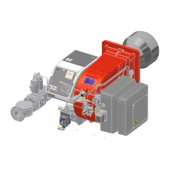
PART I: SPECIFICATIONS PART I: SPECIFICATIONS GENERAL FEATURES Note: the figure is indicative only Control panel with startup switch Gas train Electrical panel Cover Blast tube + Combustion head Flange Silencer Actuator Air pressure switch 10 Oil manifold 11 Pump Gas operation: the gas coming from the supply line, passes through the valves group provided with filter and governor. - Page 6 ED = micro-processor control, with inverter Technical Specifications HR91 MG.. HR92 MG.. HR93 MG.. HR91 LG.. HR92 LG.. HR93 LG.. BURNER TYPE 480 - 2670 480 - 3050 550 - 4100 480 - 2670 480 - 3050 550 - 4100 min.
- Page 7 PART I: SPECIFICATIONS HR525 HR525 HR512 MG.. HR515 MG.. HR520 MG.. BURNER TYPE MG...50 MG...xx 600 - 4.500 770 - 5.200 1000 - 6.400 2000 - 6.700 2000 - 8.000 min. - max. kW Output Natural gas - Light oil Fuel Category see next paragraph...
- Page 8 PART I: SPECIFICATIONS Gas categories and countries of application GAS CATEGORY COUNTRY AT, ES, GR, SE, FI, IE, HU, IS, NO, CZ, DK, GB, IT, PT, CY, EE, LV, SI, MT, SK, BG, LT, RO, TR, CH LU, PL 2E( R ) B 2ELL Fuel Type...
- Page 9 1437 1002 535 875 313 592 145 1520 1085 642 942 353 *DN = gas valves size NOTE: the overall dimensions are referred to burners provided with Siemens VGD valves. B*: SPECIAL blast tube lengths must be agreed with Cib Unigas...
- Page 10 874 343 270 626 132 1646 1002 538 875 310 639 145 1726 1082 642 942 353 NOTE: the overall dimensions are referred to burners provided with Siemens VGD valves. B*: SPECIAL blast tube lengths must be agreed with Cib Unigas...
- Page 11 1437 1002 535 875 313 592 145 1520 1085 642 942 353 *DN = gas valves size NOTE: the overall dimensions are referred to burners provided with Siemens VGD valves. B*: SPECIAL blast tube lengths must be agreed with Cib Unigas...
- Page 12 874 343 270 626 132 1646 1002 538 875 310 639 145 1726 1082 642 942 353 NOTE: the overall dimensions are referred to burners provided with Siemens VGD valves. B*: SPECIAL blast tube lengths must be agreed with Cib Unigas...
- Page 13 HR91 - HR92 - HR93 - 3I2MG-21 v0 Hydraulic diagram LEGEND POS OIL TRAIN Filter Flexible hose Pump and pressure governor oil inlet Electrical motor Solenoid valve Solenoid valve oil outlet Oil distributor Pressure gauge Pressure governor Pressure switch 16.1 One-way valve 16.1 One-way valve...
- Page 14 HR512 - HR515 - HR520 - HR525 Fig. 4 - 3I2MG-23 v0 Hydraulic diagram BY OTHERS 3I2MG23 LEGEND rev.0 BY BURNER CONSTRUCTOR POS OIL TRAIN Filter Flexible hose Pump and pressure governor Electrical motor Flexible hose Solenoid valve Flexible hose 3-way solenoid valve oil inlet Flexible hose...
- Page 15 PART I: SPECIFICATIONS How to read the burner “Performance curve” To check if the burner is suitable for the boiler to which it must be install- Campo di lavoro bruciatori led, the following parameters are needed: Tipo P60 Mod. M-xx.x.IT.A.0.50 - M-.xx.x.IT.A.0.65 furnace input, in kW or kcal/h (kW = kcal/h/860);...
-
Page 16: Performance Curves
PART I: SPECIFICATIONS Performance Curves HR91 HR92 1200 1600 2000 2400 2800 3200 1200 1600 2000 2400 2800 HR93 HR512 500 1000 1500 2000 2500 3000 3500 4000 4500 1500 2500 3500 4500 HR515 HR520 1500 2500 3500 4500 5500... - Page 17 PART I: SPECIFICATIONS Pressure in the Network / gas flow rate curves (natural gas) HR91 MG.. HR92 MG.. HR93 MG.. HR512 MG.. HR515 MG.. HR520 MG.. HR525 MG.. Rp2 HR525 MG.. DN65-80-100 ATTENTION: the gas rate value is quoted on the x-axis, the related network pressure is quoted on the y-axis (pressure value in the combustion chamber is not included).
- Page 18 PART I: SPECIFICATIONS Pressure in the Network / gas flow rate curves (LPG) HR91 LG.. HR93 LG.. HR512 LG.. HR520 LG..
- Page 19 PART I: SPECIFICATIONS The values in the diagrams refer to natural gas with a calorific value of 8125 kcal/Stm (15°C, 1013 mbar) and a density of 0.714 kg/Stm The values in the diagrams refer to GPL with a calorific value of 22300 kcal/Stm (15°C, 1013 mbar) and a density of 2.14 kg/ .
- Page 20 PART I: SPECIFICATIONS Gas pressure burner head vs natural gas flow rate Curves are referred to pressure = 0 mbar in the combustion chamber! HR91 MG.. HR92 MG.. 100 120 140 160 180 200 220 240 260 280 300 40 60 80 100 120 140 160 180 200 220 240 260 280 300 320 340 HR93 MG..
- Page 21 PART I: SPECIFICATIONS Pressure - rate in combustion head curves (LPG) Curves are referred to pressure = 0mbar in the combustion chamber! HR91 LG.. HR93 LG.. 100 110 120 130 140 150 160 HR512 LG.. HR520 LG.. 1 0 0...
- Page 22 PART II: INSTALLATION PART II: INSTALLATION MOUNTING AND CONNECTING THE BURNER Packing The burners are despatched in wooden crates whose dimensions are: 9x series: 1672mm x 1072mm x 1016mm (L x P x H) 5xx series: 1886mm x 1456mm x 1120mm (L x P x H) ...
- Page 23 PART II: INSTALLATION Matching the burner to the boiler The burners described in this manual have been tested with combustion chambers that comply with EN676 regulation and whose dimensions are described in the diagram . In case the burner must be coupled with boilers with a combustion chamber smaller in dia- meter or shorter than those described in the diagram, please contact the supplier, to verify that a correct matching is possible, with respect of the application involved.
- Page 24 PART II: INSTALLATION GAS TRAIN CONNECTIONS WARNING: before executing the connections to the gas pipe network, be sure that the manual cutoff valves are closed. ATTENTION: it is recommended to mount filter and gas valves to avoid that extraneous material drops inside the valves, during maintenance and cleaning operation of the filters (both the filters outside the valves group and the ones built-in the gas valves).
-
Page 25: Mounting Positions
PART II: INSTALLATION Gas Filter (if provided) The gas filters remove the dust particles that are present in the gas, and prevent the elements at risk (e.g.: burner valves, counters and regulators) from becoming rapidly blocked. The filter is normally installed upstream from all the control and on-off devices. ATTENTION: it is reccomended to install the filter with gas flow parallel to the floor in order to prevent dust fall on the safety valve during maintenance operation. - Page 26 PART II: INSTALLATION DUNGS MBE Componenti e posizione dei pressostati PGMIN pressostato gas di minima VD-V VD-R VD-V VD-R PGMIN pressostato gas di minima (alternativo a 1) PGCP pressostato gas controllo perdite PGMAX pressostato gas di massima Azionatore con stabilizzatore di pressione incorpo- rato Azionatore On-Off Corpo valvola (Filettata)
- Page 27 PART II: INSTALLATION Siemens VGD20.. e VGD40.. Componenti e posizione dei pressostati PGMIN pressostato gas di minima SKP25 SKP25 PGMIN pressostato gas di minima (alternativo a 1) SKP15 SKP15 PGCP pressostato gas controllo perdite PGMAX pressostato gas di massima Azionatore con stabilizzatore di pressione incorpo- rato Azionatore On-Off Corpo valvola (Filettata)
- Page 28 PART II: INSTALLATION Siemens VGD Pressure taps Legenda pi Inlet pressure Strainer pm Pressure between val- (G 1/4") (G 1/8") (G 1/4") (G 3/4") (G 1/8") (G 1/4") (G 1/8") po Outlet pressure Once the gas train in installed, execute the electrical connections for all its items (gas valves group, gas proving system, pressure switches).
-
Page 29: Gravity Circuit
PART II: INSTALLATION OIL TRAIN CONNECTIONS Hydraulic diagrams for light oil supplying circuits GRAVITY CIRCUIT RING CIRCUIT 1 Manual valve 2 Light oil filter 3 Light oil feeding pump 4 One way valve 5 Flexible hoses 6 Relief valve SUCTION CIRCUIT NOTE: in plants where gravity or ring feed systems are provided, install an automatic interception device. - Page 30 PART II: INSTALLATION Burners come out from the factory provided for double-pipe systems. They can be suited for single-pipe system (recommended in the case of gravity feed) as decribed before.To change from a 1-pipe system to a 2-pipe-system, insert the by-pass plug G (as for ccw-rota- tion- referring to the pump shaft).
- Page 31 PART II: INSTALLATION Suntec T.. Viscosity 3 - 75 cSt Oil temperature 0 - 150 °C Minimum suction pressure - 0.45bar to prevent gasing Maximum suction pressure 5 bar Rated speed 3600 rpm max. Inlet G3/4 Pressure gauge port G1/4 Vacuum gauge port to measure the inlet vacuum G1/4 To pressure adjusting valve G3/4 "Note: pump with “C”...
-
Page 32: Electrical Connections
PART II: INSTALLATION Diesel filters Item Note Connection Max. operating Max. operating Filtering Protec- pressure temperature degree tion 20151PE (*) 3/8” 1 bar -20, 60 °C 100 μ 20201PL (*) 3/8” 1 bar -20, 60 °C 100 μ GA70501 1” 4 bar 90 °C IP65... - Page 33 PART III: OPERATION PART III: OPERATION DANGER! Incorrect motor rotation can seriously damage property and injure people. DANGER: During commissioning operations, do not let the burner operate with insufficient air flow (danger of formation of carbon monoxide); if this should happen, make the gas decrease slowly until the normal combustion values are achieved.
-
Page 34: Gas Operation
PART III: OPERATION - BURNER FRONT PANEL h min s Main switch (0=Off, 1=GAS, 2=OIL) CMF switch (0=stop, 1=low flame, 2=high flame, 3=automatic) - fully modulating burners only Gas valves EV2 operation signalling lamp Gas valves EV1 operation signalling lamp Gas pressure switch signalling lamp Oil pump in operation lamp Oil valve EVG operation signalling lamp... - Page 35 PART III: OPERATION control box drives the actuator opening and when the maximum opening position is reached, the pre-purge time counting starts. At the end of the pre-purge time, the actuator is in the light oil ignition position: the ignition transformer is energised (lamp B4 on); ...
-
Page 36: User Interface
PART III: OPERATION User interface The AZL2x.. display is shown below: The keys functions are the following: Service mode Info mode Parametere setting mode Plant heat request Oil pre-heater energised Fan motor energised Ignition transformers energised Open valves Flame Lock+unlock codes Closing actuator Opening actuator Unit measure... - Page 37 PART III: OPERATION Manifacturer level (OEM) PHASES LIST During operation, the following program phases are shown. The meaning for each phase is quoted in the table below Fase / Funzione Function Ph00 Fase blocco Lockout phase Ph01 Fase di sicurezza Safety phase Ph10 t10 = tempo raggiungimento posizione riposo...
-
Page 38: Info Level
PART III: OPERATION Info level To enter the Info level, proceed as follows: in any menu position, press keys + and - at the same time, then the program will start again: the display will show OFF. until the display will show InFo, Press the enter (InFo) key then il will show the first code (167) flashing, on the right side it will show the data entered. -
Page 39: Service Level
PART III: OPERATION If a message like the one below is shown during operation, it means that the burner is locked out and the Errore code is shown (in the example “error code:4”); this message is alternating with another message Diagnostic code (in the example “diagnostic code:3”). -
Page 40: Parameter Description
PART III: OPERATION The service level shows all the information about flame intensity, actuators position, number and lock codes: Parameter Description Flame intensity % output, if set = automatic operation Actuators position, 00=combustibile; 01= aria Lock-outs number 701..725 Lock-outs History (see chapter 23 in the LMV2x manual) .the first parameter will be “954”: the percentage of flame is shown on the right. -
Page 41: Head Adjustment
PART III: OPERATION Head adjustment The burner is factory-adjusted with the combustion head in the "MAX" position, accordingly to the maximum power. To operate the bur- ner at a lower power, progressively shift back the combustion head, towards the "MIN" position, screwing the screw VRT. Attention! if it is necessary to change the head position, repeat the air and fuel adjustments described above. - Page 42 PART III: OPERATION ADJUSTING THE GAS VALVES GROUP Multibloc MB-DLE The multibloc unit is a compact unit consisting of two valves, gas pressure switch, pressure stabilizer and gas filter. C VS The valve is adjusted by means of the RP regulator after slackening the locking screw VB by a number of turns.
- Page 43 PART III: OPERATION Calibration air and gas pressure switches The air pressure switch locks the control box if the air pressure is not the one requested. If it happens, unlock the burner by means of the control box unlock pushbutton, placed on the bur- ner control panel.
- Page 44 PART III: OPERATION Adjustment procedure for light oil operation The light oil flow rate can be adjusted choosing a by-pass nozzle that suits the boiler/utilisation output and setting the delivery and return pressure values according to the ones quoted on the table below and the diagram on Fig. 20 (as far as reading the pressure values, see next paragraphs).
- Page 45 PART IV: MAINTENANCE PART IV: MAINTENANCE At least once a year carry out the maintenance operations listed below. In the case of seasonal servicing, it is recommended to carry out the maintenance at the end of each heating season; in the case of continuous operation the maintenance is carried out every 6 months.
- Page 46 PART IV: MAINTENANCE Oil Flow Rate Settings Once the air and gas flow rates are adjusted, turn the burner off, switch to the oil operation (OIL, on the burner control panel). with the electrical panel open, prime the oil pump acting directly on the related CP contactor (see next picture): check the pump motor rotation and keep pressing for some seconds until the oil circuit is charged;...
- Page 47 PART IV: MAINTENANCE Gas filter maintenance WARNING: Before opening the filter, close the manual cutoff valve downstream the filter and bleed the gas; check that inside the filter there is no pressurised gas. Per pulire o sostituire il filtro gas procedere nel modo seguente: MB-DLE MB-DLE 415 - 420 B01...
- Page 48 PART IV: MAINTENANCE MultiBloc VD-V VD-R Mounting to push position 1. Position VD on VB, fig. 2+3. 2. Slide VD forward up to the stop, fig. 4. 3. Screw VD on with 2 M5 screws for each, max. 5 Nm/44 in.-lb., fig. 5/6. 4.
- Page 49 PART IV: MAINTENANCE 1 Inlet 2 Return 3 Gun opening E Oil piping connections H Cover L Oil gun Adjusting the electrodes position Adjust the electrodes position, according to the measures (in mm) shown on the next picture. HR9x.. generator gasket inspection glass head stroke limitation slot HR5x..
-
Page 50: Seasonal Stop
PART IV: MAINTENANCE 10÷15 3÷5 3÷4 10÷13 8÷10 10÷13 1.1 Checking the detection current To check the detection signal follow the scheme in the picture below. If the signal is less than the value indicated, check the position of the detection electrode or detector, the electrical contacts and, if necessary, replace the electrode or the detector. Device Flame detector Minimum detection signal... - Page 51 PART IV: MAINTENANCE TROUBLESHOOTING GUIDE Gas operation * No electric power supply * Restore power supply * Main switch open * Close switch * Thermostats open * Check set points and thermostat connections * Bad thermostat set point or broken thermostat * Reset or replace the thermostat * No gas pressure * Restore gas pressure...
- Page 52 PART IV: MAINTENANCE * No electric power supply * Wait for electric power supply is back * Main switch open * Close the switch * Thermostats open * Check set points and thermostat connections * Bad thermostat set point or broken thermostat * Set or replace the thermostat * No gas pressure * Restore gas pressure...
- Page 56 C.I.B. UNIGAS S.p.A. Via L.Galvani, 9 - 35011 Campodarsego (PD) - ITALY Tel. +39 049 9200944 - Fax +39 049 9200945/9201269 web site: www.cibunigas.it - e-mail: cibunigas@cibunigas.it Note: specifications and data subject to change. Errors and omissions excepted.
- Page 57 AZL2x - LMV2x/3x Burner Management System Service manual 03/2023 M12916CD Rev. 3.4...
- Page 58 INDEX MICROPROCESSOR CONTROLLED SYSTEM..........................6 User interface....................................6 Parameters level (heating engineer)............................... 8 Setting menu....................................9 Block 000: Internal Parameter ..............................10 Block 100: General information..............................10 Block 200: Burner control................................13 Block 400: Setting air/fuel ratio curves............................25 Block 500: Air/fuel ratio control ..............................26 Block 600: Actuators ..................................
- Page 59 DANGERS, WARNINGS AND NOTES OF CAUTION THIS MANUAL IS SUPPLIED AS AN INTEGRAL AND ESSENTIAL PART OF THE PRODUCT AND MUST BE DELIVERED TO THE USER. INFORMATION INCLUDED IN THIS SECTION ARE DEDICATED BOTH TO THE USER AND TO PERSONNEL FOLLOWING PRO- DUCT INSTALLATION AND MAINTENANCE.
- Page 60 DIRECTIVES AND STANDARDS do not leave the equipment exposed to weather (rain, sun, etc.) unless expressly required to do so; Gas burners European directives: do not allow children or inexperienced persons to use equipment; - Directive 2009/142/EC - Gas Appliances; The unit input cable shall not be replaced by the user.
- Page 61 -EN 55014-1Electromagnetic compatibility - Requirements for household appliances, electric tools and similar apparatus. -UNI EN 676 (Gas Burners; -CEI EN 60335-1(Household and similar electrical appliances - Safety. Part 1: General requirements; - EN 50165 Electrical equipment of non-electric appliances for household and similar purposes.
- Page 62 MICROPROCESSOR CONTROLLED SYSTEM The control system is made of the Siemens LMV central unit that performs all the burner control functions and of the Siemens AZL local programming unit that interfaces the system with the user. Keys Burner AZL2.. Air actuator Fuel actuator LMV2..
- Page 63 The keys functions are the following: Key F Used to adjust the “fuel” actuator position (Fuel): : While pressing the F key, the “fuel” actuator position can be changed by means of the + and - keys. Key A Used to adjust the “air” actuator position (Air): While pressing the A key, the “air”...
- Page 64 Parameters level (heating engineer)
- Page 65 Setting menu The seeting menu is divided into different blocks: Bloc. Descrizione Description Password Internal parameters OEM / Service Informazioni generali General OEM / Service / Info Controllo bruciatore Burner control OEM / Service Controllo bruciatore (solo LMV26) Burner control (LMV26 only) OEM / Service Curve rapporto Ratio curves...
- Page 66 Block 000: Internal Parameter Param. Descrizione Description Password Password livello assistenza (ingegnere del Password heating engineer (4 characters) calore) Password livello OEM (costruttore del brucia- Password OEM (5 characters) tore) Start backup / restore via AZL2.../ PC sof- tware (set parameter to 1) Index 0: Create backup Index 1: Execute restore Error dia- Start backup/restore via AZL2x/PC gnostics via negative values...
- Page 67 Frequenza di rete Mains frequency 0 = 50 Hz 0 = 50 Hz Service / Info 1 = 60 Hz 1 = 60 Hz Luminosità display Display brightness Service / Info Tempo dopo il quale, se non viene premuto nessun tast il software esce dalla modalita Timeout for menu operation (default value = programmazione (valore fabbrica = 60min - 60min - range: 10 - 120 min)
- Page 68 Numero totale di partenze (non azzerabile) Total number of startups Service / Info Volume combustibile (azzerabile da OEM) Fuel volume (resettable by OEM) Service / Info Fuel 1(secondo combustibile)Ore di eserci- Fuel 1: Operation hours resettable Service / Info zio (azzerabile da Service) Fuel 1 (secondo combustibile) Numero di Fuel 1: Number of startups resettable Service / Info...
- Page 69 Block 200: Burner control Param. Descrizione Description Password Modalità funzionamento bruciatore ( rampa Burner operating mode (fuel train, modula- combustibile, modulante / multistadio, servo- ting / multistage, actuators, etc..) comandi, ecc.) __= non definito (cancellazione curve) __= undefined (delete curves) 1 = accensione diretta a gas (G mod) 1 = gas direct ignition (G mod) 2 = accensione tramite pilota gas con attacco...
- Page 70 15 = gas rampa Gp1 modulante pneumatico 15 = Gp1 mod pneu without actuator senza servomotori (Gp1 mod pneu) 16 = Gp2 mod pneu without actuator 16 = gas rampa Gp2 modulante pneumatico 17 = Lo 2-stage without actuator senza servomotori (Gp2 mod pneu) 18 = Lo 3-stage without actuator 17 = olio LO 2 stadi senza servomotori 19 = G mod gas actuator only...
- Page 71 Gas: sonda rilevazione fiamma attivo (valore Gas: active detector flame evaluation (default fabbrica = 1) value = 1) OEM / Service 0 = QRB../QRC.. 1 = ION / QRA.. Gas: Preventilazione (valore fabbrica = 1) Gas: Pre-purging (default value = 1) 1 = attivo 1 = active 0 = non attivo...
- Page 72 Gas: Pressostato gas di minima (default = 1) Gas: Pressure switch-min input 0 = inattivo 0 = inactive 1 = pressostato gas di minima (a monte val- 1 = pressure switch-min (upstream of fuel vola V1) valve 1 (V1)) 2 = controllo perditavalvole via pressostato 2 = valve proving via pressure switch-min OEM / Service (montato tra le valvole V1 e V2)
- Page 73 Gas: tempo pressione atmosferica controllo Gas: proving test time atmospheric pres- tenuta (valore fabbrica = 10s - range impo- sure (default value = 10s - range:0.2s - 60s) stazione:0.2s - 60s) Gas: tempo riempimento controllo tenuta Gas: proving test filling time (default value = (valore fabbrica = 3s - range imposta- 3s - range:0.2s - 10s) zione:0.2s - 10s)
- Page 74 Olio: Intervallo 1 (valore fabbrica = 2s - Oil: Interval 1 (default value = 2s - OEM / Service range impostazione:0.2s - 60min) range:0.2s - 60min) Olio: tempo di sicurezza 2 (TSA2) (valore Oil: safety time 2 (TSA2) (default value = 3s fabbrica = 3s - range impostazione:0.2 - 10s) - range:0.2 - 10s) Olio: Intervallo 2 (valore fabbrica = 2s -...
- Page 75 Block 300: Burner control (only with LMV26) Param. Descrizione Description Password Combustibile 1 : Modalità funzionamento bru- Fuel 1 : Burner operating mode (fuel train, ciatore ( rampa combustibile, modulante / modulating / multistage, actuators, etc..) multistadio, servocomandi, ecc.) __= non definito (cancellazione curve) __= undefined (delete curves) 1 = accensione diretta a gas (G mod) 1 = gas direct ignition (G mod)
- Page 76 11 = olio 2 stadi con accensione tramite pilota 11 = LoGp 2-stage (LOGp 2-stage) 12 = Lo mod 2 fuel valves 12 = olio modulante con 2 valvole combusti- 13 = LoGp mod 2 fuel valves bile (LOmod 2 valvole) 14 = G mod pneu without actuator 13 = olio modulante con 2 valvole combusti- 15 = Gp1 mod pneu without actuator...
- Page 77 Combustibile 1 - Gas: tempo di preaccen- Fuel 1 - Gas: Preignition time (default value = sione (valore fabbrica = 2s - range imposta- 2s - range: 0.2s - 60min) OEM / Service zione:0.2s - 60min) Combustibile 1 - Gas: tempo di sicurezza 1 Fuel 1 - Gas: Safety time 1 (TSA1) (default (TSA1) (valore fabbrica = 3s - range impo- value = 3s - range: 0.2 - 10s)
- Page 78 Limite ripetizioni perdita di fiamma (valore Repetition limit loss of flame (default value= 2 fabbrica = 2 - range impostazione:1 - 2) - range:1 - 2) Fuel 1 - Gas: execution proving test (default Combustibile 1 - Gas: esecuzione controllo value= 2) tenuta (valore fabbrica = 2) 0 = no controllo tenuta...
- Page 79 Fuel 1 - Oil: prepurging (default value = 1) Combustibile 1 - Olio: preventilazione (valore fabbrica = 1) 0 = deactivated 1 = attivo 1 = activated 0 = non attivo 0 = deactivated OEM / Service In ambito civile la norma EN267 rende obbli- WARNING: in the civil field, the prepurge is gatoria la preventilazione.
- Page 80 Limite ripetizioni perdita di fiamma (valore Repetition limit value loss of flame (default fabbrica = 2 - range impostazione:1 - 2) value = 2 - range:1 - 2) Fuel 1 - Oil: time oil ignition (default value = Combustibile 1 - Olio: tempo iniezione olio (valore fabbr.
- Page 81 Block 400: Setting air/fuel ratio curves Param. Descrizione Description Password Curve controllo servocomando combustibile Ratio control curve fuel actuator (F): it acces- (F): si accede alla lista dei punti da impostare ses to the parameter list of the points to be set OEM / Service (da P0 a P9) - consultare paragrafo “Imposta- (P0 to P9) - see paragrapf “Setting the curves”...
- Page 82 Block 500: Air/fuel ratio control Param. Descrizione Description Password No-flame position fuel actuator Posizione servocomando combustibile in assenza di fiamma (no-flame) Indice 0 = posizione di sosta = 0° Index 0 = no-load position = 0° OEM / Service Indice 1 = posizione preventilazione = 0° Index 1 = prepurge position = 0°...
- Page 83 Activation of VSD / PWM fan (PWM = Pulse- Width Modulation) Activation of VSD / PWM fan OEM / Service 0=deactived 1=actived (PWM = Pulse-Width Modulation) Parameter 544 Modulation Modulation Modulation Modulation Actuator Actuating speed param- Max. delta between the curve points eter 613 OEM / Service Actuator...
- Page 84 Block 600: Actuators Param. Descrizione Description Password Impostazione punto di riferimento Selection of reference point Indice 0 = combustibile Index 0 = fuel Indice 1 = aria Index 1 = air 0 = chiuso (<0°) 0 = closed (<0°) 1 = aperto (>90°) 1 = open (>90°) Direzione rotazione del servocomando Actuator’s direction of rotation...
- Page 85 Tipo di riferimento dei servocomandi index 0 = fuel (default = 0 (riferimento stan- dard) Type of referencing index 1 = air (default = 0 (riferimento stan- Index 0 = fuel dard) Index 1 = air 0 = standard 0 = standard 1 = fermo entro il raggio utile 1 = stop within usable range 2 = fermi interni (SQN1...)
- Page 86 Configurazione uscita analogica % di carico Configuration of analog output (default value (valore fabbrica = 0) = 0) 0 = DC 0..10 V 0 = DC 0..10 V OEM / Service 1 = DC 2..10 V 1 = DC 2..10 V 2 = DC 0/2..10 V 2 = DC 0/2..10 V ATTENTION: as for SQM3x actuators, set the direction according to the acutator function.
- Page 87 Block 700: Error history Param. Descrizione Description Password Storico errori: 701 - 725.01.codice Error history: 701 - 725.01.code Service / Info Storico errori: 701 - 725.02.codice diagnostico Error history: 701 - 725.02.diagnostic code ° Service / Info Storico errori: 701 - 725.03.classe errore Error history: 701 - 725.03.error class °...
- Page 88 Block 900: Process data Param. Descrizione Description Password Potenza attuale (valore fabbrica = 0% - range Current output (default value = 0% - range = impostazione = 0-100%) 0-100%) Service / Info Indice 0 = combustibile Index 0 = fuel Indice 1 = aria Index 1 = air Posizione incrementale servocomandi (valore...
- Page 89 Actuators references An incremental transducer is used to ensure position feedback. Referencing of the actuators must be performed after power-on. In addition, at the end of each shutdown in phase 10, the actuators are referenced to ensure that individual stepping errors, which could lead to shutdown, do not accumulate.
-
Page 90: Commissioning The Burner
COMMISSIONING THE BURNER The LMV2x complete programming must be performed on units that has never been set before or reset units (e.g. spare parts). The programming procedure is performed by setting the following main parameters: if LMV.. is a spare part, insert burner ID (parameter 113) at least 4 digit. type of fuel train (parameter “201”) air/fuel ratio curvepoints (Block “400”) maximum load percentage (parameter “546”) - Page 91 the types of fuel trains are the following: Param. Descrizione Description Password Modalità funzionamento bruciatore ( rampa Burner operating mode (fuel train, mod / multi- comb., mod. / multistadio, servocom., ecc.) stage, actuators, etc.) __= non definito (cancellazione curve)___= __= undefined (delete curves) 1 = accensione diretta a gas (G mod) 1 = gas direct ignition(G mod) 2 = accensione tramite pilota gas con attacco...
- Page 92 Lo 3-stage In the example the Gmod gas train has been set (Configuration “1”). Choose the fuel train by pressing ENTER, then press “+” / “-”. Press ENTER to confirm: number “1” will appear on the right side of the display.
- Page 93 CAUTION: at the first burner adjustment, it is recommended to set the maximum output P9 at the same value (or little higher) of the ignition point, in order to safely reach point P9 next (see next paragraph). By pressing “+” the display will show: The burner is ready to startup.
-
Page 94: Warm Setting
Warm setting Once pressed button “enter” and the chain thermostats open (X5-03 terminals), the LMV.. show Ph12.Then close the chain termostat and the unit performs the prepurge cycle (see “Phases List”) and stops at the ignition point P0 without ignition anyway. By pressing “+”, the burners lights abd the air/fuel ratio can be properly set in presence of flame. -
Page 95: Cold Setting
P5, keep pressing “-” unitl “Calc” is displayed. The curve will be processed again downwards point P1. Fuel deviation between two following points: 25°max. 12 press “-” to go through the lower points and check the combustion values, if necessary change the points as described above. 13 By pressing ESC, at the end of the points adjusments, the parameter “546”... - Page 96 BURNER STARTUP WITH LMV2x ALREADY PROGRAMMED Once the LMV turns on, the AZL display will show The burners is basically factory set. The air/fuel ratio curve is set with the maximum output point P9 a little higher or equal to P0. To adjust the burner on the plant site, adjust the maximum output point to the flow rate values really requested.
- Page 97 Set the air/fuel ratio curvepoints as described on chapter “Programming the LMV2x” Note: the other phases are Ph60 = operation (OP= in modulation) Ph62 = travelling to shutdown Ph70 = off but in prepurge after the burntime Ph72 = travelling to postpurging Ph74 = postpurge (countdown is displayed) Press ESC the parameter “546”...
- Page 98 Reset / manual lockout The system can be manually locked by simultaneously pressing the ENTER (InFo) button and any other button on the AZL2..This function allows the user to stop the system from the operating level should an emergency occur. When making a reset, the following actions are carried out: Alarm relay and the fault display are off ...
- Page 99 Entering the Parameter levels By means of a proper use of the keys, it is possible to enter the various level parameters, as shown in the following flow chart: The burner and consequently the LMV2x.. are factory set; the air and fuel curves as set as well.
- Page 100 Info level To enter the Info level, proceed as follows: in any menu position, press keys + and - at the same time, then the program will start again: the display will show OFF. , until the display will show InFo, Press the enter (InFo) key then il will show the first code (167) flashing, on the right side it will show the data entered.
- Page 101 10 Press InFo for more than three seconds or for more than three seconds orto return to the normal display. If a message like the one below is shown during operation, it means that the burner is locked out and the Errore code is shown (in the example “error code:4”); this message is alternating with another message Diagnostic code (in the example “diagnostic code:3”).
- Page 102 Service level To enter the Service mode, press InFo until the display will show: The service level shows all the information about flame intensity, actuators position, number and lock codes: Parameter Description Flame intensity % output, if set = automatic operation Actuators position, 00=combustibile;...
- Page 103 PHASES LIST Fase /Phase Funzione Function Ph00 Fase blocco Lockout phase Ph01 Fase di sicurezza Safety phase Ph10 t10 = tempo raggiungimento posizione riposo t10 = home run Ph12 Pausa Standby (stationary) t22 = tempo di salita ventilatore (motore ventilatore t22 = fan ramp up time (fan motor = ON, safety Ph22 = ON, valvola intercettazione di sicurezza = ON)
- Page 104 BACKUP PARAMETER WITH AZL2x On the AZL2x you can save the configuration to download on another appliance LMV. To do this: access up, press F and A at the same time enter the password following the procedure on chapter “Programming LMV2x”. Press ENTER until the display will show: with the button go to the group 000 of the parameters and press...
- Page 105 RESTORE PARAMETER FROM AZL2x TO LMV.. To copy the previously saved configuration on AZL2x proceed as follows: access up, press F and A at the same time enter the password following the procedure on chapter “Programming LMV2x”. Press ENTER until the display will show: To copy the configuration from AZL2x to LMV.
- Page 106 ERROR CODE TABLE...
- Page 121 WIRING DIAGRAM Wiring connection for LMV20 Electrical supply Burner flange Fanmotor input Safety loop Lokout signal Continuous fan operator Valve External valveSV gnition transformer Valve Operation sgnal Reset Reserve Common Increase output Pressure switch leakage test Decrease input gasPGCP ON/OFF thermosta Minimum gas pressure switch Air pressure switch LUFT...
- Page 122 Wiring variants for LMV27 ConnectorX75 2 - Fuel meter input 1 - Supply fuel meter ConnectorX5-02 ConnectionsPmax...
- Page 123 Wiring variants for LMV26 ConnectorX08-04 / X09-04 2 - Fuel 0 1 - Fuel1 ConnectorX75 2 - Fuel meter input 1 - Supply fuel meter ConnectorX64 5 -Power supply speed sensor 4 -Speed sensor input 3 - PWM (Pulse Width Modulation) speed output 2 - GND (signal reference) 1 -Controller input (4÷20mA) ConnectorX74...
- Page 124 Wiring variants for LMV37 ConnectorX75 2 - Fuel meter input 1 - Supply fuel meter ConnectorX5-02 Connections Pmax ConnectorX64 5 -Power supply speed sensor 4 -Speed sensor input 3 - PWM (Pulse Width Modulation) speed output 2 - GND (signal reference) 1 -Controller input (4÷20mA) ConnectorX74 5 -Supply...
- Page 128 C.I.B. UNIGAS S.p.A. Via L.Galvani, 9 - 35011 Campodarsego (PD) - ITALY Tel. +39 049 9200944 - Fax +39 049 9200945/9201269 web site: www.cibunigas.it - e-mail: cibunigas@cibunigas.it Note: Specifications and and data subject to change. Errors and omissions excepted.
Need help?
Do you have a question about the HR91 and is the answer not in the manual?
Questions and answers