Sign In
Upload
Manuals
Brands
Miller Manuals
Welding System
907275
User Manuals: Miller 907275 MIG Welding System
Manuals and User Guides for Miller 907275 MIG Welding System. We have
2
Miller 907275 MIG Welding System manuals available for free PDF download: Owner's Manual
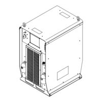
Miller 907275 Owner's Manual (56 pages)
Brand:
Miller
| Category:
Welding System
| Size: 1 MB
Table of Contents
Table of Contents
3
Section 1 − Safety Precautions - Read before Using
7
Symbol Usage
7
Arc Welding Hazards
7
Additional Symbols for Installation, Operation, and Maintenance
9
California Proposition 65 Warnings
10
Principal Safety Standards
10
EMF Information
10
Section 2 − Consignes de Sécurité − Lire Avant Utilisation
11
Symboles Utilisés
11
Dangers Relatifs au Soudage à L'arc
11
Dangers Supplémentaires en Relation Avec L'installation, le Fonctionnement et la Maintenance
13
Proposition Californienne 65 Avertissements
14
Principales Normes de Sécurité
14
Informations Relatives aux CEM
14
Section 3 − Definitions
15
Additional Safety Symbols and Definitions
15
Miscellaneous Symbols and Definitions
17
Section 4 − Specifications
18
Serial Number and Rating Label Location
18
Unit Specifications
18
Dimensions and Weight
18
Duty Cycle and Overheating
19
Volt-Ampere Curves
19
Environmental Specifications
20
Section 5 − Installation
21
Selecting a Location
21
Connection Diagram
21
Rear Panel Receptacles and Supplementary Protectors
22
Network Wire Feeder Receptacle Functions
22
Electrical Service Guide
23
Connecting 3−Phase Input Power
24
Section 6 − Recommended Setup Procedures
26
Weld Output Terminals and Selecting Cable Sizes
26
Weld Output Terminals
26
Connecting to Weld Output Terminals
27
Welding Circuit
28
Arranging Welding Cables to Reduce Welding Circuit Inductance
29
Using Multiple Welding Power Sources
30
Voltage Sensing Lead and Work Cable Connections for Multiple Welding Arcs
31
Section 7 − Operation
34
Front Panel Switches
34
Options
34
Section 8 − Maintenance
35
Routine Maintenance
35
Blowing out Inside of Unit
35
Section 10 − Troubleshooting
38
Removing Cover and Measuring Input Capacitor Voltage
38
Process Control Module PC4 Diagnostic Leds
39
Diagnostic Leds on Process Control Module PC4
40
Network and Module Status Leds
40
Troubleshooting
41
Section 11 − Electrical Diagrams
42
Section 12 − Parts List
44
Advertisement
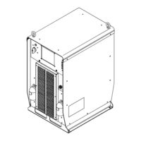
Miller 907275 Owner's Manual (52 pages)
Brand:
Miller
| Category:
Welding System
| Size: 2 MB
Table of Contents
Table of Contents
3
Section 1 − Safety Precautions - Read before Using
7
Symbol Usage
7
Arc Welding Hazards
7
Additional Symbols for Installation, Operation, and Maintenance
9
California Proposition 65 Warnings
10
Principal Safety Standards
10
EMF Information
10
Section 2 − Consignes de Sécurité − Lire Avant Utilisation
11
Symboles Utilisés
11
Dangers Relatifs au Soudage à L'arc
11
Dangers Supplémentaires en Relation Avec L'installation, le Fonctionnement et la Maintenance
13
Proposition Californienne 65 Avertissements
14
Principales Normes de Sécurité
15
Information EMF
15
Section 3 − Definitions
17
Manufacturer's Warning Label Definitions
17
WEEE Label
18
Symbols and Definitions
19
Section 4 − Installation
20
Serial Number and Rating Label Location
20
Specifications
20
Dimensions and Weight
20
Duty Cycle and Overheating
21
Volt-Ampere Curves
21
Selecting a Location
22
Connection Diagram
22
Rear Panel Receptacles and Supplementary Protectors
23
Connecting to Weld Terminals
24
Network Wire Feeder Receptacle Functions
25
Electrical Service Guide
25
Connecting Input Power
26
Section 5 − Recommended Setup Procedures
27
Selecting Weld Cable Sizes
27
Welding Circuit
28
Arranging Welding Cables to Reduce Welding Circuit Inductance
29
Using Multiple Welding Power Sources
30
Voltage Sensing Lead and Work Cable Connections for Multiple Welding Arcs
31
Section 6 − Operation
34
Front Panel Switches
34
Section 7 − Maintenance
35
Routine Maintenance
35
Blowing out Inside of Unit
35
Section 8 − Safety Precautions for Servicing
36
Symbol Usage
36
Servicing Hazards
36
California Proposition 65 Warnings
37
EMF Information
37
Section 9 − Troubleshooting
38
Removing Cover and Measuring Input Capacitor Voltage
38
Process Control Module PC4 Diagnostic Led's
39
Diagnostic Led's on Process Control Module PC4
39
Network and Module Status Led's
40
Troubleshooting
41
Section 10 − Electrical Diagrams
42
Section 11 − Parts List
44
Advertisement
Related Products
Miller 907275003
Miller 907275011
Miller 907539002
Miller 907731001
Miller 907759
Miller 907772
Miller 907661
Miller 907660001
Miller 907844
Miller 907408
Miller Categories
Welding System
Welding Accessories
Camera Accessories
Portable Generator
Motorcycle Accessories
More Miller Manuals
Login
Sign In
OR
Sign in with Facebook
Sign in with Google
Upload manual
Upload from disk
Upload from URL