Advertisement
Quick Links
VALVE FOR "ULTRA" REPLACEMENT PARTS
Key No.
Part No.
Description
1
01013130
Handle
2
03018160
Pin for Handle
3
01013131
Fixation for 1.5" 4-Way Valve Handle
¢4 x 12 Self-Drilling Screw
4
03011003
5
01013132
Pressing Ring
6
01181060
Washer for 1.5" 4-Way Valve Handle
7
02011095
O-Ring for Rotor
8
06021014
Plastic Pressure Gauge with O-Ring (40Psi)
9
01013134
Body
10
89280104
Sight Glass with O-Ring
11
89281601
1.5" 4-way Valve Rotor Assembly
12
02311010
Spider Gasket
13
430395045
O-Ring for Diffuser
Valve Position
Function
FILTER
Normal Filtration and Vacuuming
BACKWASH
Cleaning Filter by reversing the flow
RINSE
Used after backwash to flush dirt from valve
WASTE
By-passes filter, used for vacuuming to waste or lowering water level
RECIRCULATE
By-passes filter for circulating water to pool
CLOSED
Shuts off all flow to filter or pool
!
THIS FILTER OPERATES UNDER HIGH PRESSURE. WHEN ANY PART OF THE CIRCULATING
SYSTEM (e.g., CLAMP, PUMP, FILTER, VALVES, ETC.) IS SERVICED, AIR CAN ENTER THE
SYSTEM AND BECOME PRESSURIZED . PRESSURIZED AIR CAN CAUSE THE LID OR VALVE TO
BE BLOWN OFF WHICH CAN RESULT IN SEVERE INJURY, DEATH, OR PROPERTY DAMAGE
TURN PUMP OFF BEFORE CHANGING VALVE POSITION.
!
TO PREVENT DAMAGE TO THE PUMP AND FOR PROPER OPERATION OF THE SYSTEM,
!
CLEAN PUMP STRAINER AND SKIMMER BASKETS REGULARLY.
!
DO NOT UNSCREW SCREWS OF FLANGE CLAMP WHILE PUMP IS RUNNING.
QTY
1
1
1
3
1
1
2
1
1
1
1
1
1
WARNING
4
FSU-8TP FSU-8P
1
2
3
4
5
6
7
8
9
10
11
12
* Install filtration system including pump,filter tank and multiport valve.
* The filter system should be installed as close as possibie to the swimming pool and preferably at a level
of 0.50 metres below the surface of the water in the swimming pool. Make sure there is drainage available
at the place where the filter is to be installed.
* PUMP
13
1.Only qualified,licensed personnel should install pump and wiring.
2.Electrical Contractors Please Note: All 220 volt 50Hz pump must be wired to the main power supply
trough an approved and correctly rated contractor.
3.Allow for gate valve in suction piping.
4.Pump suction and discharge connections have moulded in
beyond these stops.
* FILTER TANK and MULTIPORT VALVE
1.Loading the sand media.Filter sand media is loaded through the top opening of the filter.
a.Loosen the plastic clamps from tank neck.
b.Cap internal pipe with plastic cap to prevent sand from entering it.
c.We recommend filling tank approximately 1/2 way with water to provide a cushion effect when the filter
sand is poured in. This helps protect the under-drain laterals from excessive shock.
d.Carefully pour in correct amount and grade of filter sand.Be sure center pipe remains centered in opening.
Sand surface should be leveled and should come to about the middle of the filter tank.Remove plastic cap
from internal pipe.
2.Assemble filter control valve to filter tank.
a.Insert filter control valve(with O'ring in place)into the tank neck,taking care that the center pipe slips
into the hole in the bottom of the valve.
b.Place two plastic clamps around valve flange and tank neck and tighten just enough so that the valve may
Be rotated on tank for final positioning.
c.Carefully screw pressure gauge(with O'ring in place)into tapped hole in valve body.Do not over-tighten.
d.Connect pump to control valve opening marked PUMP with hose.After connections are made,tighten
clamps with screwdrive,tapping around clamp with screwdrive handle to help seat valve flange clamp.
3.Make return to pool pipe connection to control valve opening marked RETURN and complete other
necessary plumbing connections,suction lines to pump,waste,etc.
4.To prevent water leakage,be sure all pipe connections are tight.
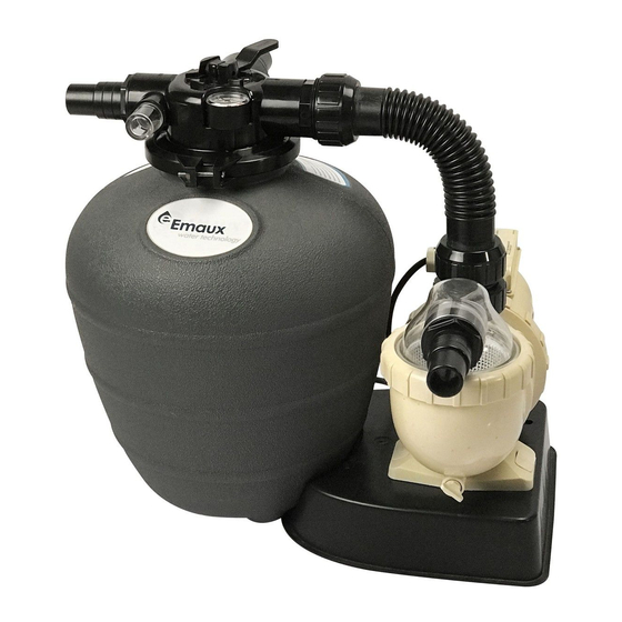
FILTER & PUMP COMBO
Installation & Operating
Instruction
INSTALLATION
thread stops,do not try to screw pipe in
1
EMFS24030680
Advertisement

Related Manuals for emaux FSU-8TP


Summary of Contents for emaux FSU-8TP
- Page 1 VALVE FOR "ULTRA" REPLACEMENT PARTS FSU-8TP FSU-8P FILTER & PUMP COMBO Key No. Part No. Description Installation & Operating 01013130 Handle Instruction 03018160 Pin for Handle 01013131 Fixation for 1.5" 4-Way Valve Handle ¢4 x 12 Self-Drilling Screw 03011003 01013132...
- Page 2 AMU020TP AQUA-MINI Pump (with Timer & Pre-Filter) The Emaux pump must be connected to the main power supply by an approved and licensed electrician. If the supply cord is damaged, it must be replaced by the manufacturer, service agent, or similarly qualified individuals to avoid hazards.
Need help?
Do you have a question about the FSU-8TP and is the answer not in the manual?
Questions and answers