
Related Manuals for Daikin FXKA25AMVEB


Summary of Contents for Daikin FXKA25AMVEB
- Page 1 Installer and user reference guide VRV system air conditioner FXKA20AMVEB FXKA25AMVEB FXKA32AMVEB FXKA40AMVEB FXKA50AMVEB FXKA63AMVEB...
-
Page 2: Table Of Contents
Table of contents Table of contents 1 About the documentation About this document..............................2 General safety precautions About the documentation.............................. 2.1.1 Meaning of warnings and symbols........................ For the installer ................................2.2.1 General................................2.2.2 Installation site............................... 2.2.3 Refrigerant — in case of R410A or R32......................2.2.4 Electrical................................. - Page 3 Table of contents For the installer 14 About the box 14.1 Indoor unit..................................14.1.1 To unpack and handle the unit........................14.1.2 To remove the accessories from the indoor unit..................15 About the units and options 15.1 Identification .................................. 15.1.1 Identification label: Indoor unit........................15.2 About the indoor unit..............................
-
Page 4: About The Documentation
The original instructions are written in English. All other languages are translations of the original instructions. Technical engineering data ▪ A subset of the latest technical data is available on the regional Daikin website (publicly accessible). FXKA-A Installer and user reference guide VRV system air conditioner 4P747548-2 –... - Page 5 About the documentation ▪ The full set of the latest technical data is available on the Daikin Business Portal (authentication required). FXKA-A Installer and user reference guide VRV system air conditioner 4P747548-2 – 2023.11...
-
Page 6: General Safety Precautions
General safety precautions 2 General safety precautions 2.1 About the documentation ▪ The original instructions are written in English. All other languages are translations of the original instructions. ▪ The precautions described in this document cover very important topics, follow them carefully. -
Page 7: For The Installer
WARNING Improper installation or attachment of equipment or accessories could result in electrical shock, short-circuit, leaks, fire or other damage to the equipment. ONLY use accessories, optional equipment and spare parts made or approved by Daikin unless otherwise specified. WARNING Make sure installation, testing and applied materials comply with applicable legislation (on top of the instructions described in the Daikin documentation). -
Page 8: Installation Site
General safety precautions WARNING Provide adequate measures to prevent that the unit can be used as a shelter by small animals. Small animals that make contact with electrical parts can cause malfunctions, smoke or fire. CAUTION Wear adequate personal protective equipment (protective gloves, safety glasses,…) when installing, maintaining or servicing the system. - Page 9 General safety precautions DANGER: RISK OF EXPLOSION Pump down – Refrigerant leakage. If you want to pump down the system, and there is a leak in the refrigerant circuit: ▪ Do NOT use the unit's automatic pump down function, with which you can collect all refrigerant from the system into the outdoor unit.
-
Page 10: Electrical
General safety precautions ▪ Whether the unit is factory charged with refrigerant or non-charged, in both cases you might need to charge additional refrigerant, depending on the pipe sizes and pipe lengths of the system. ▪ ONLY use tools exclusively for the refrigerant type used in the system, this to ensure pressure resistance and prevent foreign materials from entering into the system. - Page 11 General safety precautions WARNING ▪ ONLY use copper wires. ▪ Make sure the field wiring complies with the applicable legislation. ▪ All field wiring MUST be performed in accordance with the wiring diagram supplied with the product. ▪ NEVER squeeze bundled cables and make sure they do NOT come in contact with the piping and sharp edges.
- Page 12 General safety precautions Install power cables at least 1 meter away from televisions or radios to prevent interference. Depending on the radio waves, a distance of 1 meter may NOT be sufficient. NOTICE ONLY applicable if the power supply is three‑phase, and the compressor has an ON/ OFF starting method.
-
Page 13: Specific Installer Safety Instructions
WARNING Make sure installation, servicing, maintenance, repair and applied materials follow the instructions from Daikin (including all documents listed in “Documentation set”) and, in addition, comply with applicable legislation and are performed by qualified persons only. In Europe and areas where IEC standards apply, EN/IEC 60335-2-40 is the applicable standard. - Page 14 Specific installer safety instructions WARNING ▪ All wiring MUST be performed by an authorised electrician and MUST comply with the national wiring regulation. ▪ Make electrical connections to the fixed wiring. ▪ All components procured on-site and all electrical construction MUST comply with the applicable legislation.
-
Page 15: Instructions For Equipment Using R32 Refrigerant
WARNING Make sure installation, servicing, maintenance and repair comply with instructions from Daikin and with applicable legislation (for example national gas regulation) and are executed ONLY by authorised persons. WARNING ▪... -
Page 16: Installation Space Requirements
Specific installer safety instructions CAUTION Field-made refrigerant joints indoors shall be tightness tested. The test method shall have a sensitivity of 5 grams per year of refrigerant or better under a pressure of at least 0,25 times the maximum allowable pressure. No leak shall be detected. 3.1.1 Installation space requirements CAUTION The total refrigerant charge and/or releasable charge m... -
Page 17: For The User
For the user FXKA-A Installer and user reference guide VRV system air conditioner 4P747548-2 – 2023.11... -
Page 18: User Safety Instructions
User safety instructions 4 User safety instructions Always observe the following safety instructions and regulations. 4.1 General WARNING If you are NOT sure how to operate the unit, contact your installer. WARNING This appliance can be used by children aged from 8 years and above and persons with reduced physical, sensory or mental capabilities or lack of experience and knowledge if they have been given supervision or instruction concerning... -
Page 19: Instructions For Safe Operation
User safety instructions ▪ Units are marked with the following symbol: This means that electrical and electronic products may NOT be mixed with unsorted household waste. Do NOT try to dismantle the system yourself: dismantling the system, treatment of the refrigerant, of oil and of other parts MUST be done by an authorised installer and MUST comply with applicable legislation. - Page 20 User safety instructions CAUTION ▪ NEVER touch the internal parts of the controller. ▪ Do NOT remove the front panel. Some parts inside are dangerous to touch and appliance problems may happen. For checking and adjusting the internal parts, contact your dealer. WARNING This unit contains electrical and hot parts.
- Page 21 User safety instructions WARNING Do NOT place a flammable spray bottle near the air conditioner and do NOT use sprays near the unit. Doing so may result in a fire. WARNING Keep any required ventilation openings clear of obstructions. WARNING If the supply cord is damaged, it MUST be replaced by the manufacturer, its service agent or similarly qualified persons in order to avoid a hazard.
- Page 22 User safety instructions DANGER: RISK OF ELECTROCUTION To clean the air conditioner or air filter, be sure to stop operation and turn all power supplies OFF. Otherwise, an electrical shock and injury may result. WARNING Be careful with ladders when working in high places. DANGER: RISK OF ELECTROCUTION Disconnect the power supply for more than 10 ...
- Page 23 User safety instructions WARNING ▪ Do NOT pierce or burn refrigerant cycle parts. ▪ Do NOT use cleaning materials or means to accelerate the defrosting process other than those recommended by the manufacturer. ▪ Be aware that the refrigerant inside the system is odourless.
-
Page 24: About The System
About the system 5 About the system WARNING ▪ Do NOT modify, disassemble, remove, reinstall or repair the unit yourself as incorrect dismantling or installation may cause an electrical shock or fire. Contact your dealer. ▪ In case of accidental refrigerant leaks, make sure there are no naked flames. The refrigerant itself is entirely safe, non-toxic and mildly flammable, but it will generate toxic gas when it accidentally leaks into a room where combustible air from fan heaters, gas cookers, etc. -
Page 25: Information Requirements For Fan Coil Units
Sound power level (heating, per speed setting dB(A) if applicable) H: High, M: Medium, L: Low Contact details: DAIKIN INDUSTRIES CZECH REPUBLIC s.r.o. U Nové Hospody 1155/1, 301 00 Plzeň Skvrňany, Czech Republic FXKA20AMVEB 1.5 0.034 H: 46.0, M: 43.5, H: 50.0, M: 46.0, L: 41.0... -
Page 26: User Interface
User interface 6 User interface CAUTION ▪ NEVER touch the internal parts of the controller. ▪ Do NOT remove the front panel. Some parts inside are dangerous to touch and appliance problems may happen. For checking and adjusting the internal parts, contact your dealer. -
Page 27: Before Operation
Before operation 7 Before operation CAUTION "4 User safety instructions" [ 18] to acknowledge all related safety instructions. This operation manual is for the following systems with standard control. Before initiating operation, contact your dealer for the operation that corresponds to your system type and mark. -
Page 28: Operation
Operation 8 Operation 8.1 Operation range INFORMATION For the operation limits see the technical data of the connected outdoor unit. 8.2 About operation modes INFORMATION Depending on the installed system, some operation modes will not be available. ▪ The air flow rate may adjust itself depending on the room temperature or the fan may stop immediately. -
Page 29: Special Heating Operation Modes
Operation 8.2.2 Special heating operation modes Operation Description Defrost To prevent a loss of heating capacity due to frost accumulation in the outdoor unit, the system will automatically switch to defrost operation. During defrost operation, the indoor unit fan will stop operation, and the following icon will appear on the home screen: The system will resume normal operation after approximately 6... - Page 30 Operation a Cooling operation b Heating operation 2 Horizontal airflow The following horizontal airflow directions can be set by the user interface: Direction Display Fixed position. The indoor unit blows air in 1 of 5 fixed positions. Swing. The indoor unit alternates between the 5 positions.
-
Page 31: To Operate The System
Operation 8.3 To operate the system INFORMATION For setting of the operation mode, airflow direction or other settings, see the reference guide or operation manual of the user interface. FXKA-A Installer and user reference guide VRV system air conditioner 4P747548-2 – 2023.11... -
Page 32: Energy Saving And Optimum Operation
Energy saving and optimum operation 9 Energy saving and optimum operation CAUTION NEVER expose little children, plants or animals directly to the airflow. NOTICE Do NOT place objects below the indoor and/or outdoor unit that may get wet. Otherwise condensation on the unit or refrigerant pipes, air filter dirt or drain blockage may cause dripping, and objects under the unit may get dirty or damaged. -
Page 33: Maintenance And Service
Maintenance and service 10 Maintenance and service 10.1 Precautions for maintenance and service CAUTION "4 User safety instructions" [ 18] to acknowledge all related safety instructions. NOTICE NEVER inspect or service the unit by yourself. Ask a qualified service person to perform this work. However, as end user, you may clean the air filter and the unit exterior. -
Page 34: Cleaning The Unit Exterior And Air Filter
Maintenance and service 10.2 Cleaning the unit exterior and air filter CAUTION Turn off the unit before cleaning the unit exterior and air filter. NOTICE ▪ Do NOT use gasoline, benzene, thinner polishing powder or liquid insecticide. Possible consequence: Discoloration and deformation. ▪... -
Page 35: Maintenance Before A Long Stop Period
Maintenance and service 3 Clean the air filters. Use a vacuum cleaner or wash with water. If the air filter is very dirty, use a soft brush and neutral detergent. 4 Dry the air filters in the shadow. 5 Reattach the air filters and close panel. 6 Turn ON the power. -
Page 36: About The Refrigerant Leakage Sensor
Maintenance and service WARNING ▪ The refrigerant inside the unit is mildly flammable, but normally does NOT leak. If the refrigerant leaks in the room and comes in contact with fire from a burner, a heater, or a cooker, this may result in fire, or the formation of a harmful gas. ▪... - Page 37 Maintenance and service CAUTION When replacing the R32 refrigerant leakage sensor, replace it with the sensor specified by the manufacturer (refer to the spare parts list). In case of detection when the unit is operating 1 The user interface displays error "A0-11" and emits an alarm sound. The status indicator blinks.
-
Page 38: Troubleshooting
Troubleshooting 11 Troubleshooting If one of the following malfunctions occurs, take the measures shown below and contact your dealer. WARNING Stop operation and shut OFF the power if anything unusual occurs (burning smells etc.). Leaving the unit running under such circumstances may cause breakage, electrical shock or fire. -
Page 39: Symptoms That Are Not System Malfunctions
Troubleshooting Malfunction Measure The system operates but ▪ Check if air inlet or outlet of outdoor or indoor cooling or heating is unit is not blocked by obstacles. Remove any insufficient. obstacles and make sure the air can flow freely. ▪... -
Page 40: Symptom: White Mist Comes Out Of A Unit (Indoor Unit)
Troubleshooting 11.1.4 Symptom: White mist comes out of a unit (Indoor unit) ▪ When humidity is high during cooling operation. If the interior of an indoor unit is extremely contaminated, the temperature distribution inside a room becomes uneven. It is necessary to clean the interior of the indoor unit. Ask your dealer for details on cleaning the unit. -
Page 41: Symptom: The Fan Runs After The Unit Is Turned Off Via The User Interface
Troubleshooting 11.1.11 Symptom: The fan runs after the unit is turned off via the user interface ▪ Cooling mode: After stopping the unit in cooling, the suction grill and flaps close. The indoor fan runs for 30 minutes to dry out inside of the unit, preventing mould and odours. -
Page 42: Relocation
Relocation 12 Relocation Contact your dealer to remove and reinstall the entire unit. Moving units requires technical expertise. FXKA-A Installer and user reference guide VRV system air conditioner 4P747548-2 – 2023.11... -
Page 43: Disposal
Disposal 13 Disposal NOTICE Do NOT try to dismantle the system yourself: dismantling of the system, treatment of the refrigerant, oil and other parts MUST comply with applicable legislation. Units MUST be treated at a specialised treatment facility for reuse, recycling and recovery. FXKA-A Installer and user reference guide VRV system air conditioner... -
Page 44: For The Installer
For the installer FXKA-A Installer and user reference guide VRV system air conditioner 4P747548-2 – 2023.11... -
Page 45: About The Box
About the box 14 About the box Keep the following in mind: ▪ At delivery, the unit MUST be checked for damage and completeness. Any damage or missing parts MUST be reported immediately to the claims agent of the carrier. ▪... - Page 46 About the box 1× 1× 1× 8× 6× 4× 4× 3× 2× 2× 1× 1× A Located under the unit a Installation and operation manual b General safety precautions B Located under the unit c Paper pattern for installation C Located on the side of the unit d Drain hose e Metal clamp f Clamp washer for hanger bracket...
-
Page 47: About The Units And Options
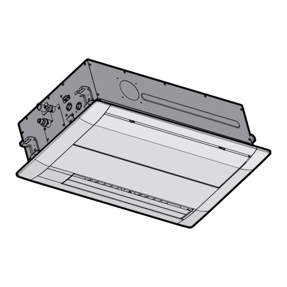
About the units and options 15 About the units and options In this chapter 15.1 Identification................................... 15.1.1 Identification label: Indoor unit ..........................15.2 About the indoor unit................................15.3 Components ................................... 15.4 Combining units and options ..............................15.4.1 Possible options for the indoor unit ........................15.1 Identification NOTICE When installing or servicing several units at the same time, make sure NOT to switch... -
Page 48: Combining Units And Options
About the units and options e f g h °C a Indoor unit b Discharge air c Suction air d Air filter e Drain pipe f Refrigerant piping g Power supply cable h Interconnection cable i User interface cable j User interface 15.4 Combining units and options INFORMATION Certain options may NOT be available in your country. - Page 49 About the units and options ▪ An additional Installation box for the optional output PCB is required; see the option list of the indoor unit. For installation of the installation box, refer to the manual of the installation box. The wiring between the main PCB and the optional output PCB must be led together with the transmission cable;...
-
Page 50: Unit Installation
Unit installation 16 Unit installation In this chapter 16.1 Preparing the installation site ..............................16.1.1 Installation site requirements of the indoor unit....................16.2 Mounting the indoor unit............................... 16.2.1 Guidelines when installing the indoor unit......................16.2.2 Guidelines when installing the drain piping ......................16.1 Preparing the installation site Choose an installation location with sufficient space to transport the unit in and out of the site. - Page 51 Unit installation Do NOT install the unit in the following places: ▪ In places where a mineral oil mist, spray or vapour may be present in the atmosphere. Plastic parts may deteriorate and fall off or cause water leakage. It is NOT recommended to install the unit in the following places because it may shorten the life of the unit: ▪...
-
Page 52: Mounting The Indoor Unit
Unit installation 16.2 Mounting the indoor unit 16.2.1 Guidelines when installing the indoor unit INFORMATION Optional equipment. When installing optional equipment, also read the installation manual of the optional equipment. Depending on the field conditions, it might be easier to install the optional equipment first. ▪... - Page 53 Unit installation e Ceiling opening dimensions f Indoor unit dimensions g Suspension bolt pitch Class A (mm) B (mm) C (mm) D (mm) 20~32 860~910 40~63 1240 1303 1260~1310 1350 Side view (mm) a Suspension bolt b Ceiling NOTICE Make sure the decoration panel overlaps the ceiling opening by at least 20 mm. The distance between the indoor unit and the ceiling opening must be ≤35 ...
-
Page 54: Guidelines When Installing The Drain Piping
Unit installation a Level NOTICE Do NOT install the unit tilted. Possible consequence: If the unit is tilted against the direction of the condensate flow (the drain piping side is raised), the float switch might malfunction and cause water to drip. 16.2.2 Guidelines when installing the drain piping Make sure condensation water can be evacuated properly. - Page 55 Unit installation c Rising drain piping (vinyl pipe of 25 mm nominal diameter and 32 mm outer diameter) (field supply) d Hanging bars (field supply) ▪ Combining drain pipes. You can combine drain pipes. Make sure to use drain pipes and T-joints with the correct gauge for the operating capacity of the units. (mm) a T-joint To connect the drain piping to the indoor unit...
- Page 56 Unit installation A' A' ≤4 mm A-A' a Drain pipe connection (attached to the unit) b Vinyl tape c Drain hose (accessory) d Metal clamp (accessory) e Large sealing pad (accessory) f Drain piping (field supply) Drain outlet for maintenance Pull out the plug.
- Page 57 Unit installation a Power supply terminal block b User interface terminal block 2 Turn ON the power. 3 Start fan only operation (see the reference guide or the service manual of the user interface). 4 Gradually pour approximately 1 l of water through the air discharge outlet, and check for leaks.
-
Page 58: Piping Installation
Piping installation 17 Piping installation In this chapter 17.1 Preparing refrigerant piping ..............................17.1.1 Refrigerant piping requirements ........................... 17.1.2 Refrigerant piping insulation ..........................17.2 Connecting the refrigerant piping............................17.2.1 About connecting the refrigerant piping....................... 17.2.2 Precautions when connecting the refrigerant piping ................... 17.2.3 Guidelines when connecting the refrigerant piping ..................... -
Page 59: Refrigerant Piping Insulation
Piping installation Outer diameter (Ø) Temper grade Thickness (t) Ø 6.4 mm (1/4") Annealed (O) ≥0.8 mm 9.5 mm (3/8") 12.7 mm (1/2") Depending on the applicable legislation and the maximum working pressure of the unit (see "PS High" on the unit name plate), larger piping thickness might be required. 17.1.2 Refrigerant piping insulation ▪... -
Page 60: Precautions When Connecting The Refrigerant Piping
Piping installation 17.2.2 Precautions when connecting the refrigerant piping INFORMATION Also read the precautions and requirements in the following chapters: ▪ "2 General safety precautions" [ 6] ▪ "17.1 Preparing refrigerant piping" [ 58] DANGER: RISK OF BURNING/SCALDING NOTICE ▪ Do NOT use mineral oil on flared part. ▪... -
Page 61: Guidelines When Connecting The Refrigerant Piping
Piping installation NOTICE Do NOT open the refrigerant stop valve before checking the refrigerant piping. When you need to charge additional refrigerant it is recommended to open the refrigerant stop valve after charging. 17.2.3 Guidelines when connecting the refrigerant piping Take the following guidelines into account when connecting pipes: ▪... -
Page 62: To Connect The Refrigerant Piping To The Indoor Unit
Piping installation a Cut exactly at right angles. b Remove burrs. 3 Remove the flare nut from the stop valve and put the flare nut on the pipe. 4 Flare the pipe. Set exactly at the position as shown in the following figure. Flare tool for R32 Conventional flare tool (clutch type) - Page 63 Piping installation b Tie wrap (accessory) c Insulation pieces: Large (gas pipe), small (liquid pipe) (accessories) d Flare nut (attached to the unit) e Refrigerant pipe connection (attached to the unit) f Unit g Sealing pads: Medium (gas pipe), Small (liquid pipe) (accessories) 1 Turn up the seams of the insulation pieces.
-
Page 64: Electrical Installation
Electrical installation 18 Electrical installation In this chapter 18.1 About connecting the electrical wiring ..........................18.1.1 Precautions when connecting the electrical wiring ....................18.1.2 Guidelines when connecting the electrical wiring ....................18.1.3 Specifications of standard wiring components ..................... 18.2 To connect the electrical wiring to the indoor unit ....................... 18.1 About connecting the electrical wiring Typical workflow Connecting the electrical wiring typically consists of the following stages:... -
Page 65: Guidelines When Connecting The Electrical Wiring
Electrical installation WARNING ▪ If the power supply has a missing or wrong N-phase, equipment might break down. ▪ Establish proper earthing. Do NOT earth the unit to a utility pipe, surge absorber, or telephone earth. Incomplete earthing may cause electrical shocks. ▪... -
Page 66: Specifications Of Standard Wiring Components
Electrical installation Use the following methods for installing wires: Wire type Installation method Single-core wire AA´ A´ Stranded conductor wire twisted to "solid-like" connection a Curled wire (single-core or twisted stranded conductor wire) b Screw c Flat washer Stranded conductor wire with round crimp-style terminal a Terminal... -
Page 67: To Connect The Electrical Wiring To The Indoor Unit
Electrical installation Power supply of the product FXKA20, 25, 32: 0.4 A FXKA40: 0.6 A FXKA50: 0.9 A FXKA63: 1.4 A MCA=Minimum circuit ampacity. Stated values are maximum values (see electrical data of indoor unit for exact values). Wiring / circuit breaker (field supplied) Power supply cable MUST comply with national wiring regulation. - Page 68 Electrical installation 2× a Service cover b Service cover handle c Sliding direction of service cover 2 User interface cable: Route the cable through the frame and connect it to the terminal block (P1, P2). 3 Transmission cable: Route the cable through the frame and connect it to the terminal block (make sure the symbols F1 and F2 match with the symbols on the outdoor unit).
- Page 69 Electrical installation TO IN/D TO OUT/D a Outdoor unit b Indoor unit c User interface d Most downstream indoor unit NOTICE For the use of group control and related limitations refer to manual of outdoor unit. CAUTION ▪ Each indoor unit has to be connected to a separate user interface. Only a safety system compatible remote controller can be used as the user interface.
-
Page 70: Commissioning
19 Commissioning NOTICE General commissioning checklist. Next to the commissioning instructions in this chapter, a general commissioning checklist is also available on the Daikin Business Portal (authentication required). The general commissioning checklist is complementary to the instructions in this chapter and can be used as a guideline and reporting template during commissioning and hand-over to the user. -
Page 71: Checklist Before Commissioning
Commissioning INFORMATION During the first running period of the unit, the required power may be higher than stated on the nameplate of the unit. This phenomenon is caused by the compressor, that needs a continuous run time of 50 hours before reaching smooth operation and stable power consumption. -
Page 72: Configuration
Configuration 20 Configuration 20.1 Field setting Make the following field settings so that they correspond with the actual installation setup and with the needs of the user: ▪ Ceiling height ▪ Air volume when thermostat control is OFF ▪ Time to clean air filter ▪... - Page 73 Configuration If you want… Then — During thermostat 12 (22) OFF at cooling Setup volume operation Monitoring 1 Monitoring 2 During thermostat 12 (22) OFF at heating Setup volume operation Monitoring 1 Monitoring 2 Only use in combination with optional remote sensor or when setting M 10 (20), SW 2, — 03 is used.
- Page 74 Configuration Setting: Thermostat differential changeover (if remote sensor is used) If the system contains a remote sensor, set the increase/decrease increments. If you want to change increments to… Then — 1°C 12 (22) 0.5°C Setting: Automatic changeover differential Set temperature difference between cooling setpoint and heating setpoint in automatic mode (availability depends on the system type).
- Page 75 Configuration FORCED Input A a Forced OFF b Input A Wiring requirements Wiring specification Sheathed vinyl cord or 2-core cable Wiring size 0.75~1.25 mm Wiring length Maximum 100 m External contact specification Contact that can make and break the min. load of DC15 V · 1 mA This setting must correspond with the needs of the user.
-
Page 76: Hand-Over To The User
Hand-over to the user 21 Hand-over to the user Once the test run is finished and the unit operates properly, make sure the following is clear for the user: ▪ Make sure that the user has the printed documentation and ask him/her to keep it for future reference. -
Page 77: Troubleshooting
Troubleshooting 22 Troubleshooting 22.1 Solving problems based on error codes If the unit runs into a problem, the user interface displays an error code. It is important to understand the problem and to take measures before resetting an error code. This should be done by a licensed installer or by your local dealer. This chapter gives you an overview of most possible error codes and their descriptions as they appear on the user interface. - Page 78 Troubleshooting Code Description Room temperature thermistor in remote controller abnormality FXKA-A Installer and user reference guide VRV system air conditioner 4P747548-2 – 2023.11...
-
Page 79: Disposal
Disposal 23 Disposal NOTICE Do NOT try to dismantle the system yourself: dismantling of the system, treatment of the refrigerant, oil and other parts MUST comply with applicable legislation. Units MUST be treated at a specialised treatment facility for reuse, recycling and recovery. FXKA-A Installer and user reference guide VRV system air conditioner... -
Page 80: Technical Data
A subset of the latest technical data is available on the regional Daikin website (publicly accessible). ▪ The full set of the latest technical data is available on the Daikin Business Portal (authentication required). 24.1 Wiring diagram 24.1.1 Unified wiring diagram legend For applied parts and numbering, refer to the wiring diagram on the unit. - Page 81 Technical data Symbol Meaning AC*, CN*, E*, HA*, HE*, HL*, HN*, HR*, Connection, connector MR*_A, MR*_B, S*, U, V, W, X*A, K*R_*, NE D*, V*D Diode Diode bridge DIP switch Heater FU*, F*U, (for characteristics, refer to Fuse PCB inside your unit) Connector (frame ground) Harness H*P, LED*, V*L...
- Page 82 Technical data Symbol Meaning Thermo switch Residual current device Resistor Thermistor Receiver Limit switch Float switch S*NG Refrigerant leak detector S*NPH Pressure sensor (high) S*NPL Pressure sensor (low) S*PH, HPS* Pressure switch (high) S*PL Pressure switch (low) Thermostat S*RH Humidity sensor S*W, SW* Operation switch SA*, F1S...
-
Page 83: Glossary
Optional equipment Equipment made or approved by Daikin that can be combined with the product according to the instructions in the accompanying documentation. Field supply Equipment NOT made by Daikin that can be combined with the product according to the instructions in the accompanying documentation. - Page 84 4P747548-2 2023.11...
Need help?
Do you have a question about the FXKA25AMVEB and is the answer not in the manual?
Questions and answers