
Subscribe to Our Youtube Channel
Related Manuals for Pentair PENTEK EPC-115-25


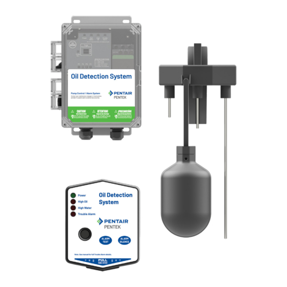
Summary of Contents for Pentair PENTEK EPC-115-25
- Page 1 ELEVATOR PUMP CONTROL SYSTEM EPC-115-25 MODEL INSTALLATION AND OPERATIONS MANUAL Pentair.com ©2024 Pentair. All Rights Reserved.
-
Page 2: Table Of Contents
TABLE OF CONTENTS SAFETY INSTRUCTIONS . . . . . . . . . . . . . . . . . . . . . . . . . . . . . . . . . . . . . . . . . . . . . . . . . . . . . . . . . . . . . . . . . . . . . . . . . . . . . . . . . . . . . . . . . . . . . . . . . . . 2 INTRODUCTION . -
Page 3: Introduction
LED will illuminate (solid) when powered. This alarm panel is used monitoring various conditions including but not limited to power, with Pentair/Pentek® Oil Detection System control panels for the pump running, high oil, high water, power loss, level sensor error... -
Page 4: Specification
SPECIFICATIONS SPECIFICATIONS ALARM PANEL: SYSTEM: Primary Power: 120VAC, 50/60 Hz Primary Power: 120VAC, 1-14 AMPS, 60 HZ Circuit Board Primary Power: 11.1VDC, 500mA maximum Phase/Pump Type: Single Phase, Simplex Circuit Board Secondary Power: 9VDC, standard 9VDC battery Pump Power Receptacle Cable:120VAC, 15A, 60 Hz Female Plug ... - Page 5 SPECIFICATIONS 10 & 11 Type 4X Enclosure (indoor/outdoor rated) 13. Sensitivity Adjustment Dial (water sensors) Clear Cover to view Interior Components (not shown; 14. IEC Motor Contactor enclosure includes lockable latch) 15. Pump Power Receptacle (pre-wired female plug) Mounting Brackets 16.
-
Page 6: Operations
OPERATION OPERATION If the test/silence switch is toggled upward during an alarm condition, it will silence the buzzer while the red alarm LED(s) The Oil Detection System single phase simplex control panel is remain illuminated. The alarm auxiliary contacts of the control used for the safe operation of pumping, alarming, and monitoring panel can be connected to an optional Oil Detection System remote of elevator sump pits, transformer vaults, and leachate well... - Page 7 OPERATION PUMP EXERCISER APPLICATION EXAMPLE: OIL DETECTION SYSTEM Factory Default: Disabled (F1 LED is OFF). This Oil Detection System example (Fig. 2) shows a typical setup for a single phase simplex control panel system and the components Description: The pump will not be exercised if idle for ...
- Page 8 OPERATION HIGH OIL ALARM CONDITION (OIL DETECTION) | SUMP LEVEL To determine the oil layer thickness in the sump/monitoring area during a high oil alarm condition, review the sensor LED status indicators for an approximate oil level in the sump. If only the F1 LED status indicator of the preset level sensor is illuminated (solid), then the oil layer will be submerging the high water, pump start, and pump stop probes.
-
Page 9: Installation
INSTALLATION It is recommended to separate the pump power receptacle INSTALLATION cable and preset level sensor cable by at least 2-inches, OIL DETECTION SYSTEM CONTROL PANEL whether the cables are in the tank or when they are above ground in separate conduits/cable grips or junction box. This model comes with four pre-installed cable grips (Fig. - Page 10 INSTALLATION PRESET LEVEL SENSOR If the preset level sensor is disconnected from the control panel and power is applied to the system, the high oil alarm Determine the mounting location and attach the preset LED and high level float activated sensor LED will illuminate, level sensor to the discharge pipe (Fig.
- Page 11 INSTALLATION SYSTEM WIRING Low Level / Redundant Off Alarm: If installing a normally open PRESET LEVEL SENSOR float switch, connect one wire to the FI input and the other wire The preset level sensor comes pre-installed from the factory. If to the ground terminal on the Oil Detection System control panel replacing, route the 5-conductor sensor cable from the mounting as listed below and shown in the diagram.
- Page 12 INSTALLATION 3-ZONE REMOTE ALARM (OPTIONAL) alarm condition. When connected, run the wire(s) towards To install/replace the battery for the backup power feature, the bottom/center of the alarm panel to go through the wiring remove the enclosure cover and install a 9VDC battery (not access hole once the enclosure cover is replaced.
- Page 13 INSTALLATION AUXILIARY CONTACTS (OUTPUTS): After the wiring is completed and before replacing the enclosure cover, run the wire(s) towards the bottom/center Terminals COM and 1A: Zone-1 (High Oil). Connects to external of the alarm panel to go through the wiring access hole once monitoring device the enclosure cover is replaced.
- Page 14 INSTALLATION PUMP POWER RECEPTACLE The pump power receptacle (female plug) comes pre-installed from the factory for a quick and easy installation of the Oil Detection System control panel. After all the steps of the installation process have been completed, connect the pump power cable into the pre-installed pump power receptacle of the Oil Detection System control panel.
-
Page 15: Settings
SETTINGS SETTINGS Toggle Settings: Press and hold the test/configure pushbutton on the Oil Detection System control panel for at least 10-seconds to DEVICE CONFIGURATIONS toggle (change) the current settings of the system. This section provides information for viewing and changing High Water, High Oil, and Trouble Alarm LEDs deactivate. -
Page 16: Testing
TESTING Hand Mode (H): the pump will start and continue to run until ALARM SILENCE the switch is toggled to the off position regardless of sensor Activate the high level float switch on the preset level sensor. status. When raised, the high oil alarm (oil detected) LED and the high Off Mode (O): the pump will remain off until the switch is ... - Page 17 TESTING With the HOA switch in the AUTO position and the probes on When the pump is running and cannot keep up with the preset level sensor out of the water, test a high oil alarm demand as the water level continues to rise touching condition by raising (activate) and lowering (deactivate) the the high water probe (shortest), the high water alarm high level float switch to verify:...
- Page 18 TESTING With the Off/Auto switch in the AUTO position, test a pump The preset level sensor wiring errors are automatically detected cycle by slowly immersing the preset level sensor into the in the application by factory default settings. Holding the test/ water (Fig.
-
Page 19: Troubleshooting
TROUBLESHOOTING SYMPTOM POSSIBLE CAUSE(S) CORRECTIVE ACTION Incoming power cable is unplugged Plug in power cable and check power Pump power cable not plugged into Connect pump power cable into panel panel receptacle Toggle HOA selector switch Pump hand-off-auto (HOA) in the OFF ... - Page 20 Fx: 888.606.5484 All indicated Pentair trademarks and logos are property of Pentair . Third party registered and unregistered trademarks and logos are the property of their respective owners . Because we are continuously improving our products and services, Pentair reserves the right to change specifications without prior notice . Pentair is an equal opportunity employer .
Need help?
Do you have a question about the PENTEK EPC-115-25 and is the answer not in the manual?
Questions and answers