
Related Manuals for Telex Audiocom ES4000A


Summary of Contents for Telex Audiocom ES4000A
- Page 1 ® T elex User Instructions Model ES4000A Intercom Expansion Station ® Audiocom Intercom Systems ® Download from Www.Somanuals.com. All Manuals Search And Download.
- Page 2 This product meets Electromagnetic Compatibility Directive 89/336/EEC. Introduction. Thank you for purchasing the Audiocom ES4000A Intercom Expansion Station. We hope the many design features of this product will satisfy your intercommu- nication requirements for many years to come. To get the most out of the ES4000A, please take a few moments to look through this booklet before using the Intercom Expansion Station for the first time.
-
Page 3: Table Of Contents
Table of Contents Description Features . Installation Unpacking Configuration Pre-check . Mounting Configurations Connection Notes . Cables . Power-Up Sidetone Adjustments . Operation Specifications Factory Service and Parts Information Download from Www.Somanuals.com. All Manuals Search And Download. -
Page 4: Description
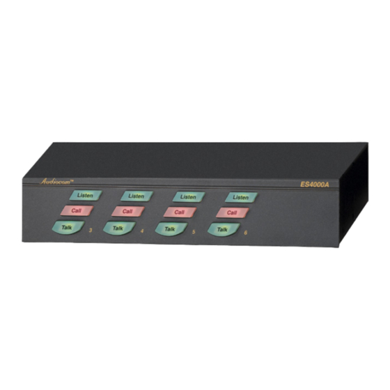
Call Call Call Call Talk Talk Talk Talk Telex SPEAKERS ® TELEX COMMUNICATIONS, INC. Minneapolis, MN U.S.A. PROGRAM INPUTS PGM VOLUME CHANNEL 3-6 OUTPUTS BAL-OUT LINE LEVEL UNBAL-IN 12-15 VDC 1 VRMS Figure 1. ES4000A Reference View (See numbered features on next page) -
Page 5: Features
Features Intercom Talk Keys: Momentary or latching (hands-free) operation possible. Call Keys: Used to call intercom channels and to indicate incoming calls. Intercom Listen Keys: Momentary or latching operation possible. Local Power Jack: The ES4000A can be powered from the intercom channels via the CHANNEL 3-6 OUTPUTS connector (9). - Page 6 Audi o co m ® nal jumper which routes the program either to the intercom channel only, or to both the intercom channel and the US2000A headset or speaker (default setting). Additionally, the program signal to the intercom channel may be turned on or off via the US2000A front panel programming.
-
Page 7: Installation
The ES4000A is supplied with the following items. Contact the shipper or your Audiocom dealer immediately if anything is damaged or missing. Detach and fill out the registration card and return it to Telex to properly register your intercom station. Quantity... - Page 8 Audi o co m ® Table 1. Configuration Switch Settings Switch Description Settings Default Number Setting DIP Switch SW1 (Internal) On (Closed): Enabled SW1-1 Program Interrupt, Ch 6 Off (Open): Disabled On (Closed): Enabled SW1-2 Program Interrupt, Ch 5 Off (Open): Disabled On (Closed): Enabled SW1-3 Program Interrupt, Ch 4...
- Page 9 Audiocom Call Send and Receive DIP Switches By default, all channels of the ES4000A can send and receive Audiocom call signals. You can disable call send or call receive capability for selected channels if desired. When the BAL / UNBAL switch on the back panel is set to the UNBAL position (for use with a Clear-Com Intercom System) the call send and call receive DIP switches have no effect.
-
Page 10: Mounting Configurations
Audi o co m ® Sidetone Trimmers These trimmers are normally adjusted after all components are connected, and they can be accessed through the bottom cover (Figure 15). Refer to the US2000A User Manual for the sidetone adjustment procedure. Mounting Configurations The ES4000A can be used on a desktop, or it can be rack mounted. - Page 11 BACK OF RACK FRONT OF RACK PS4000 (CH7 -10POWER) ® PS-4000 Reset SPS2000A (CH1/2 POWER) PS4000 (CH3 -6POWER) ® SPS2000A ® PS-4000 Combine Reset Reset Isolate Volume ® US2000A ® ES4000A Headset Mic Kill Listen Listen Listen Listen Listen Listen Call Call Panel Mic...
- Page 12 BACK OF RACK FRONT OF RACK PS2000L (CH5 POWER) PS2000L (CH6 POWER) PS2000L PS2000L ® ® Combine Combine Reset Reset Isolate Isolate PS2000L (CH3 POWER) PS2000L (CH4 POWER) ® PS2000L ® PS2000L Combine Combine Reset Reset Isolate Isolate SPS2000A (CH1 POWER) PS2000L (CH2 POWER) BOP-1000 WITH 1 XP-USPG, 1 XP-4PGM, AND 1 XP-ES4000 SPS2000A...
-
Page 13: Connection Notes
Connection Notes • Typical connections for the US2000A, ES4000A and various power supplies are shown starting with Figure 6, page 14. Select the configuration which most closely matches your intended usage. • The US2000A and ES4000A normally draw operating power from the intercom channel power supplies (SPS2000A, PS2000L, etc.). - Page 14 FRONT CH 3 - 6 XP-4PGM CHN 1 CHN 2 CHN 3 CHN 4 CONNECT TO ES-4000 CLASS 2 WIRING 2A 24VDC ES4000A BACK Telex SPEAKERS ® PROGRAM INPUTS PGM VOLUME CAN 3-6 OUTPUTS BAL-OUT UNBAL-IN LINE LEVEL 12-15 VDC...
- Page 15 SPS2000A Channel 1 Power and PS2000L All-Channel Speaker Channel 2 Power Combine / Isolate Switch Combine / Isolate Switch set to Combine set to Combine SPEAKER INPUT 1 ® ® INPUT 2 100-240 VAC 60/50 HZ 100-249 VAC 60/50 HZ CHN 1 CHN 1 CHN 2...
- Page 16 Audi o co m ® TO US2000A EXP IN CONNECTOR Note: For further informa- tion about the cable num- CH 3-6 bers, see page 22. ES4000A Telex SPEAKERS ® PROGRAM INPUTS PGM VOLUME CAN 3-6 OUTPUTS BAL-OUT LINE LEVEL UNBAL-IN...
- Page 17 TO US2000A EXP IN CONNECTOR Note: For further informa- CH 3-6 tion about the cable num- ES4000A bers, see page 22. Telex SPEAKERS ® PROGRAM INPUTS PGM VOLUME CAN 3-6 OUTPUTS BAL-OUT LINE LEVEL UNBAL-IN 12-15 VDC 1 VRMS XP-ES4000...
- Page 18 Audi o co m ® TO US2000A EXP IN CONNECTOR Note: For further informa- tion about the cable num- CH 3-6 bers, see page 22. ES4000A Telex SPEAKERS ® PROGRAM INPUTS PGM VOLUME CAN 3-6 OUTPUTS BAL-OUT LINE LEVEL UNBAL-IN...
- Page 19 UNBAL - IN CHN 1 12-15 VDC CH 1 CH 2 FROM MASTER STATION OR BELT PACK XP-ES4000 CH 3-6 ES4000A BACK Telex SPEAKERS ® PROGRAM INPUTS PGM VOLUME CAN 3-6 OUTPUTS BAL-OUT LINE LEVEL UNBAL-IN 12-15 VDC 1 VRMS...
- Page 20 Audi o co m ® TO US2000A EXP IN CONNECTOR Note: For further informa- CH 3-6 tion about the cable num- ES4000A bers, see page 22. Telex SPEAKERS ® PROGRAM INPUTS PGM VOLUME CAN 3-6 OUTPUTS BAL-OUT LINE LEVEL UNBAL-IN...
- Page 21 UNBAL - IN CHN 1 CHN 2 12-15 VDC 12-15 VDC UNBAL - IN CHN 1 CHN 2 CH 1 CH 2 CH 3-6 ES4000A CH 3-6 ES4000A Telex Telex PS-L PS-L SPEAKERS ® PS-L PS-L SPEAKERS ® PROGRAM PROGRAM...
-
Page 22: Cables
ME-50/2: 50' (15.2 m) cable with Male and Female 6-pin XLR connectors. ME-100/2: 100' (30.4 m) cable with Male and Female 6-pin XLR connectors. Y adapter cable. Sold separately. Use Telex CA-23-16. Or, build per Figure 14. 3 ft (0.91 m) speaker cable with RCA plugs. One supplied with each SPS2000A, SPK-1000, and SPK-2000. - Page 23 Shielded audio cable. Must have male 3-pin XLR connector at one end for con- nection to the XP-USPG or XP-4PGM program inputs. Pin-out for program in- puts is as follows: Pin 1: common Pin 2: + program input Pin 3: - program input 10.
- Page 24 Audi o co m ® TYPICAL 1-CHANNEL CABLE WIRING Pair 1 1 (Both wires) Pair 2 Shield Shield Cable Type: 22AWG Stranded, 2-Pair Twisted-wire, with Shield Connector Type: 3-Pin XLR Audio (Neutrik or Switchcraft) Pin 1: Common Denotes twisted pair. Pin 2: Channel Audio / Power Pin 3: Channel Audio / Power...
-
Page 25: Power-Up
Ch 3 Sidetone Ch 4 Sidetone Ch 5 Sidetone Ch 6 Sidetone Figure 15. Sidetone Trimmer Access on Bottom of ES4000A Power-Up The ES4000A channels power-up identically to channels 1 and 2 of the US2000A. Refer to the US2000A User Instructions for all power-up information. Sidetone Adjustments Use the sidetone adjustment procedure as described in the US2000A User Instruc- tions, except substitute channel 3, channel 4, etc. -
Page 26: Specifications
Audi o co m ® Specifications General Power Requirements: Voltage: Phantom Power: 24 VDC nominal (12 to 30 VDC) Local Power (with PS-L Wall-pack Power Supply or equivalent): 14 to 15 VDC Current: 65 mA, quiescent; 150 mA maximum Dimensions: 1.75" (44.5 mm) high, 8.25" (209.6 mm) wide, 10.0" (250 mm) deep Environmental Requirements: Storage: -20°C to 80°C;... - Page 27 Frequency Response EXP IN to/from Channel, EXP IN to/from EXP OUT, Channel to Speaker: 200 Hz to 8 kHz +1/-3 dB Total Harmonic Distortion: Less than 0.5 % Connector Pin-outs 12-15 VDC Jack Connector Type: 2.0 mm DC jack Internal pin: + 12 to 15 VDC External Ring: Common EXP IN Jack Connector Type: 1/8"...
- Page 28 Audi o co m ® CHANNEL 3-6 OUTPUTS Connector Connector Type: DB15F Female, 15-pin D-subminature Pin 1: Channel 3 intercom audio input/output high Pin 2: Channel 3 intercom audio input/output low Pin 3: Common Pin 4: Channel 5 intercom audio input/output high Pin 5: Channel 5 intercom audio input/output low Pin 6: Common Pin 7: Common...
-
Page 29: Factory Service And Parts Information
Non-Warranty Repairs - Equipment that is not under warranty must be sent prepaid to Telex. If requested, an estimate of repair costs will be issued prior to service. After your approval and completion of the repairs, the equipment will be returned on a col- lect basis. - Page 30 Audi o co m ® Notes Download from Www.Somanuals.com. All Manuals Search And Download.
- Page 31 Notes Download from Www.Somanuals.com. All Manuals Search And Download.
- Page 32 Addendum Document Affected: ES4000A User Instructions, Publication Number 9350-7551-000 Rev. A Addendum Number: 1 General Instructions: Use this addendum with Revision A of the user instruc- tions. This information will be included in Revision B. Page 6, item 6: The description should be 18" (457 mm) CHANNEL OUTPUT cable, 15-pin Male Dsub to 15-pin Male Dsub.
- Page 33 ® TELEX COMMUNICATIONS, INC. 12000 Portland Ave. So., Burnsville, MN 55337 U.S.A. 9350-7551-000 Rev. B , 8/00 Download from Www.Somanuals.com. All Manuals Search And Download.
- Page 34 Free Manuals Download Website h p://myh66.com h p://usermanuals.us h p://www.somanuals.com h p://www.4manuals.cc h p://www.manual-lib.com h p://www.404manual.com h p://www.luxmanual.com h p://aubethermostatmanual.com Golf course search by state h p://golfingnear.com Email search by domain h p://emailbydomain.com Auto manuals search h p://auto.somanuals.com TV manuals search h p://tv.somanuals.com...
Need help?
Do you have a question about the Audiocom ES4000A and is the answer not in the manual?
Questions and answers