Advertisement
Quick Links
Advertisement

Subscribe to Our Youtube Channel
Related Manuals for Lincoln Electric DownFlex 100-NF


Summary of Contents for Lincoln Electric DownFlex 100-NF
- Page 1 Operator’s Manual DownFlex ® 100-NF Authorized Service and Distributor Locator: www.lincolnelectric.com/locator Save for future reference Date Purchased Code: (ex: 10859) Serial: (ex: U1060512345) IM10372-A | Issue D ate Mar-21 © Lincoln Global, Inc. All Rights Reserved.
- Page 2 THANK YOU FOR SELECTING A QUALITY PRODUCT BY KEEP YOUR HEAD OUT OF THE FUMES. DON’T get too close to the arc. LINCOLN ELEC TRIC. Use corrective lenses if necessary to stay a reasonable distance away from the arc. READ and obey the Safety Data PLEASE EXAMINE CARTON AND EQUIPMENT FOR Sheet (SDS) and the warning label DAMAGE IMMEDIATELY...
- Page 3 MAGNETIC FIELDS MAY W117.2-1974. A Free copy of “Arc Welding Safety” booklet BE DANGEROUS E205 is available from the Lincoln Electric Company, 22801 St. Clair Avenue, Cleveland, Ohio 44117-1199. 2.a. Electric current flowing through any conductor BE SURE THAT ALL INSTALLATION, OPERATION, causes localized Electric and Magnetic Fields (EMF).
-
Page 4: Electric Shock Can Kill
S FETY ELECTRIC SHOCK ARC RAYS CAN BURN. CAN KILL. 3.a. The electrode and work (or ground) circuits are 4.a. Use a shield with the proper filter and cover plates to protect your electrically “hot” when the welder is on. Do eyes from sparks and the rays of the arc when welding or not touch these “hot”... - Page 5 S FETY WELDING AND CUTTING CYLINDER MAY EXPLODE IF SPARKS CAN CAUSE DAMAGED. FIRE OR EXPLOSION. 7.a. Use only compressed gas cylinders containing the correct shielding gas for the process used 6.a. Remove fire hazards from the welding area. If and properly operating regulators designed for this is not possible, cover them to prevent the welding sparks the gas and pressure used.
- Page 6 DOWNFLEX 100-NF SAFETY As a rule of thumb, for many mild steel electrode, if the air is visibly Ventilation clear and you are comfortable, then the ventilation is generally There are many methods which can be selected by the user to adequate for your work.
- Page 7 TLV and PEL values are as of October 2013. Always check Safety and 313 of the Emergency Planning and Community Right- Data Sheet (SDS) with product or on the Lincoln Electric website at to-Know Act of 1986 and of 40CFR 370 and 372.
- Page 8 DOWNFLEX 100-NF TABLE OF CONTENTS...
-
Page 9: Technical Specifications
550 LBS. (250 KG) RECOMMENDED 3000 M3/H EXTRACTION CAPACITY 1766 CFM DOWNFLEX 100-NF - 315 PA AT 3200 M3/H PRESSURE DROP DOWNFLEX 100-NF WITH OPTIONAL SPARK ARRESTERS - 450 PA AT 3000 M3/H PHYSICAL DIMENSIONS LENGTH DEPTH HEIGHT WEIGHT 54.1 IN. -
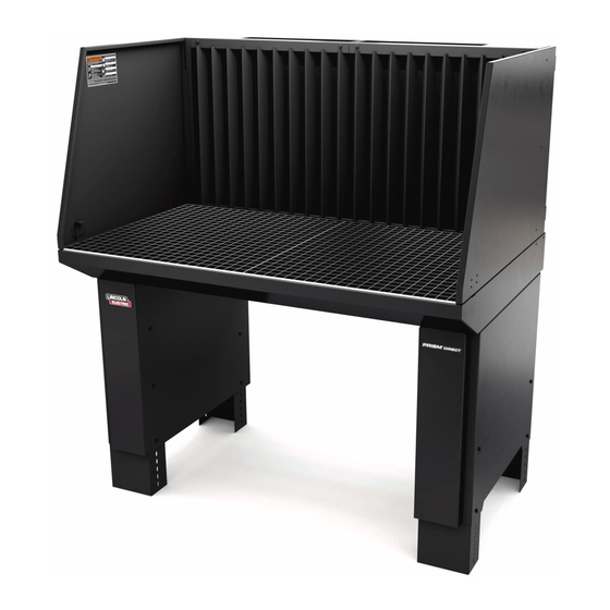
Page 10: General Description
Read this entire installation section before you start installation. GeneRal DeScRiPtion The DownFlex 100-NF table is a workbench that is to be Safety Precautions connected to an external extraction/filtration system. It is used for welding, grinding and plasma cutting applications. The DownFlex... -
Page 11: Major Components
DOWNFLEX 100-NF INSTALLATION MaJoR coMPonentS: A. Adjustable Foot (4) B. Outer Leg (2) Black C. Inner Leg (2) Red D. Dust Collection Tray E. Cover Plate for Dust Collection Tray (2) F. Backdraft Panel G. Vertical Louver Panel (2) H. Side Door Panel (2) - Page 12 DOWNFLEX 100-NF INSTALLATION WARNING FIGURE 3 Only qualified personnel should install, use or service this equipment. aSSeMblY 1. Using four screws, nuts and washers, fasten two feet (Item A) into the outer leg (Item B). See Fig. 2. The feet are adjustable in height.
- Page 13 DOWNFLEX 100-NF INSTALLATION 2. Using six screws, nuts and washers, fasten the inner leg (Item FIGURE 4 C) to the outer leg assembly completed in step 1. See Fig. 4. 3. Repeat step 1 and 2 for the other leg assembly. Space the two leg assemblies apart according to Fig.
- Page 14 DOWNFLEX 100-NF INSTALLATION 4. Using two people, lift the Dust Collection Tray (Item D) onto 5. Using 12 sheet metal screws, fasten the Cover Plates onto the FIGURE 8 the two leg assemblies and align the screw holes. Fasten the rectangular holes in the Dust Collection Tray.
- Page 15 DOWNFLEX 100-NF INSTALLATION FIGURE 11 6. Using two people, lift the Backdraft Panel onto the back of the Dust Collection Tray. Use six screws to fasten them together. FIGURE 9 See Fig. 9, 10 & 11. FIGURE 10...
- Page 16 DOWNFLEX 100-NF INSTALLATION 7. Assemble and Install the four Block Hinges onto the sides of 9. Fasten the two Vertical Louver Panels to the Backdraft Panel the Backdraft Table. See Fig. 12 & 14. Use the M8 nuts and using four screws. See Fig. 15. Ensure that the hooks on the M8 washers included with the hinge.
- Page 17 DOWNFLEX 100-NF INSTALLATION 10. Set the two Work Grids into place on the Dust Collection Tray. See Fig. 17. Secure the Work Grids with the Locking Clamps and two screws if applicable. See Fig. 18. FIGURE 17 FIGURE 18...
- Page 18 DOWNFLEX 100-NF INSTALLATION FIGURE 19 inStall oPtional K2752-2 PlaSMa cuttinG GRiD The plasma cutting work grid consists of: • 2 Grid frames 28.9 x 26.3 x 2.5 in. (735 x 669 x 64 mm) • 2 x 13 Metal bars 28.54 x 2.36 x 0.16 in.
- Page 19 DOWNFLEX 100-NF INSTALLATION inStall oPtional K2752-3 WoRKinG liGht Kit inStall oPtional KP2752-12 SPaRK aRReStoR, The working light consists of: Installation: • Lighting fixture with 7.5 ft (2.3 m) of cable and plug 1. Remove the two Vertical Louver Panels (Item A) by removing the four screws holding them to the Backdraft Panel.
- Page 20 DOWNFLEX 100-NF INSTALLATION inStall oPtional K2752-8 bench Vice inStall oPtional K2752-11 DuSt containeR MountinG bRacKet Remove the 6 sheet metal screws holding the Cover Plate to the Dust Collection Tray (component E of Figure 1), insert the Dust The bench vice mounting bracket can be mounted on the Container.
- Page 21 Mounts on top of backdraft panel. Connector will not interfere with installing downdraft table against a wall. K2752-11 Dust Container for DownFlex 100-NF - Installs in dust collection tray of downdraft table. Lid and handle on container provide for dust-free removal. DownFlex® 100- NF has mounting space for up to two containers;...
-
Page 22: Periodic Maintenance
DOWNFLEX 100-NF MAINTENANCE M INTEN NCE This product has been designed to function without problems for a long time with a minimum of maintenance. PeRioDic Maintenance The maintenance activities in the table below are strictly reserved for well trained and authorized service engineers. - Page 23 DOWNFLEX 100-NF DIAGRAMS...
- Page 26 WARNING Do not touch electrically live parts or Keep flammable materials away. Wear eye, ear and body protection. electrode with skin or wet clothing. Insulate yourself from work and AVISO DE ground. Spanish PRECAuCION No toque las partes o los electrodos Mantenga el material combustible Protéjase los ojos, los oídos y el bajo carga con la piel o ropa moja-...
- Page 27 WARNING Keep your head out of fumes. Turn power off before servicing. Do not operate with panel open or Use ventilation or exhaust to guards off. remove fumes from breathing zone. AVISO DE Spanish PRECAuCION Los humos fuera de la zona de res- Desconectar el cable de ali- No operar con panel abierto o piración.
- Page 28 We respond to our customers based on the best information applicable OSHA PEL and ACGIH TLV limits. in our possession at that time. Lincoln Electric is not in a position to warrant or guarantee such advice, and assumes no liability, with respect to such information or advice.
Need help?
Do you have a question about the DownFlex 100-NF and is the answer not in the manual?
Questions and answers