Table of Contents
Advertisement
Quick Links
WL1835MODCOM8B WLAN MIMO and Bluetooth
This user's guide describes how to use the TI WL1835MODCOM8B board to evaluate the performance of
the TI WL18MODGB module.
.......................................................................................................................
1
...................................................................................................................
2
2.1
2.2
2.3
3
3.1
4
5
6
6.1
6.2
6.3
6.4
6.5
7
7.1
7.2
8
8.1
1
2
3
4
5
6
Radio Pattern
7
8
ANT1 Polarization
9
10
11
12
ANT2 Polarization
...................................................................................................................
13
Schematic
.......................................................................................................................
14
Layer 1
.......................................................................................................................
15
.......................................................................................................................
16
SWRU359E - September 2013 - Revised September 2015
Submit Documentation Feedback
..............................................................................................................
..........................................................................................................
............................................................................................
......................................................................................................
.....................................................................................................
....................................................................................................
........................................................................................
...............................................................................................................
...........................................................................................................
......................................................................................................
................................................................................................................
................................................................................................................
...............................................................................................................
..........................................................................................................
............................................................................................
..........................................................................................................
.......................................................................................................
...........................................................................................
..............................................................................................................
..........................................................................................................
.............................................................................................................
.........................................................................................................
...............................................................................................................
..........................................................................................................
..........................................................................................................
..........................................................................................................
..........................................................................................................
..........................................................................................................
..........................................................................................................
Copyright © 2013-2015, Texas Instruments Incorporated
SWRU359E - September 2013 - Revised September 2015
.................................................................
List of Figures
WL1835MODCOM8B WLAN MIMO and Bluetooth
User's Guide
®
Module
EVM
2
3
4
5
5
6
7
9
9
10
10
11
11
12
13
15
15
16
17
17
3
6
6
10
11
11
12
12
13
13
14
14
15
17
17
18
1
®
Advertisement
Table of Contents

Related Manuals for Texas Instruments WL1835MODCOM8B


Summary of Contents for Texas Instruments WL1835MODCOM8B
-
Page 1: Table Of Contents
User's Guide SWRU359E – September 2013 – Revised September 2015 WL1835MODCOM8B WLAN MIMO and Bluetooth ® Module This user's guide describes how to use the TI WL1835MODCOM8B board to evaluate the performance of the TI WL18MODGB module. Contents ........................Warning ........................ -
Page 2: Contents 1 Warning
Wi-Fi is a registered trademark of Wi-Fi Alliance. Warning The WL1835MODCOM8B board is tested to comply with ETSI/R&TTE over temperatures from –20°C to 85°C. This board should not be modified to operate in other frequency bands other than what they are designed for. -
Page 3: Introduction
Introduction www.ti.com Introduction The WL1835MODCOM8B device is a Wi-Fi MIMO, Bluetooth, and Bluetooth Low Energy (BLE) module ® board with the TI WL18MODGB module. WL18MODGB is built-in TI WL1835 IEEE 802.11 b/g/n and Bluetooth 4.0 solutions to provide the best Wi-Fi and Bluetooth coexistence interoperability and power- saving technologies from TI. -
Page 4: Features
Direct connection to battery using external switching mode power supply supporting 4.8-V to 2.9-V operation • VIO in the 1.8-V domain WL1835MODCOM8B WLAN MIMO and Bluetooth ® Module EVM SWRU359E – September 2013 – Revised September 2015 Submit Documentation Feedback... -
Page 5: Applications
• AM335x Linux and Android™ Reference Platform Accelerates Customer Development and Time to ® Market SWRU359E – September 2013 – Revised September 2015 WL1835MODCOM8B WLAN MIMO and Bluetooth ® Module EVM Submit Documentation Feedback Copyright © 2013–2015, Texas Instruments Incorporated... -
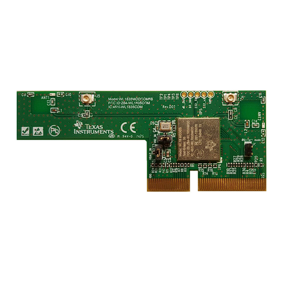
Page 6: Board Pin Assignment
Board Pin Assignment WL18MODGB Figure 2. Board Top View Figure 3. Board Bottom View WL1835MODCOM8B WLAN MIMO and Bluetooth ® Module EVM SWRU359E – September 2013 – Revised September 2015 Submit Documentation Feedback Copyright © 2013–2015, Texas Instruments Incorporated... -
Page 7: Pin Descriptions
No connection Ground N.C. No connection N.C. No connection N.C. No connection N.C. No connection Ground SWRU359E – September 2013 – Revised September 2015 WL1835MODCOM8B WLAN MIMO and Bluetooth ® Module EVM Submit Documentation Feedback Copyright © 2013–2015, Texas Instruments Incorporated... - Page 8 No connection Ground BT_FUNC2 BT_WAKE_UP Bluetooth wakeup from host N.C. No connection Ground GPIO11 General-purpose I/O WL1835MODCOM8B WLAN MIMO and Bluetooth ® Module EVM SWRU359E – September 2013 – Revised September 2015 Submit Documentation Feedback Copyright © 2013–2015, Texas Instruments Incorporated...
-
Page 9: Electrical Characteristics
FCC ID/IC ID cannot be used on the final product. In these circumstances, the OEM integrator is responsible for reevaluating the end product (including the transmitter) and obtaining a separate FCC/IC authorization. SWRU359E – September 2013 – Revised September 2015 WL1835MODCOM8B WLAN MIMO and Bluetooth ® Module EVM Submit Documentation Feedback... -
Page 10: On-Board Antenna Configuration
On-Board Antenna Configuration VSWR Figure 4 shows the antenna VSWR. Figure 4. Antenna VSWR WL1835MODCOM8B WLAN MIMO and Bluetooth ® Module EVM SWRU359E – September 2013 – Revised September 2015 Submit Documentation Feedback Copyright © 2013–2015, Texas Instruments Incorporated... -
Page 11: Efficiency
Figure 5 shows the antenna efficiency. Figure 5. Antenna Efficiency Radio Pattern Figure 6 shows the radio pattern of the WL1835MODCOM8B device. Figure 6. Radio Pattern SWRU359E – September 2013 – Revised September 2015 WL1835MODCOM8B WLAN MIMO and Bluetooth ®... -
Page 12: Ant1
On-Board Antenna Configuration www.ti.com ANT1 Figure 7 shows the ANT1 polarization of the WL1835MODCOM8B device. Figure 7. ANT1 Polarization Figure 8. ANT1 Polarization WL1835MODCOM8B WLAN MIMO and Bluetooth ® Module EVM SWRU359E – September 2013 – Revised September 2015 Submit Documentation Feedback... -
Page 13: Ant2
On-Board Antenna Configuration www.ti.com Figure 9. ANT1 Polarization ANT2 Figure 10 shows the ANT2 polarization of the WL1835MODCOM8B device. Figure 10. ANT2 Polarization SWRU359E – September 2013 – Revised September 2015 WL1835MODCOM8B WLAN MIMO and Bluetooth ® Module EVM Submit Documentation Feedback... -
Page 14: Ant2 Polarization
On-Board Antenna Configuration www.ti.com Figure 11. ANT2 Polarization Figure 12. ANT2 Polarization WL1835MODCOM8B WLAN MIMO and Bluetooth ® Module EVM SWRU359E – September 2013 – Revised September 2015 Submit Documentation Feedback Copyright © 2013–2015, Texas Instruments Incorporated... -
Page 15: Circuit Design
1.1nH 1.2pF 0402 NU_0.3pF 0402 0402 0402 0402 U.FL-R-SMT(10) U.FL-R-SMT(10) U.FL U.FL Figure 13. Schematic SWRU359E – September 2013 – Revised September 2015 WL1835MODCOM8B WLAN MIMO and Bluetooth ® Module EVM Submit Documentation Feedback Copyright © 2013–2015, Texas Instruments Incorporated... -
Page 16: Bill Of Materials (Bom)
R16, R17, R18, R19, R21, R22, R23, R24, R25, R26, R27, R28, R29, R30, R31, R32 RES 0402 / 10K / ±5% WR04X103 JTL WL1835MODCOM8B WLAN MIMO and Bluetooth ® Module EVM SWRU359E – September 2013 – Revised September 2015 Submit Documentation Feedback... -
Page 17: Layout Guidelines
Layout Guidelines www.ti.com Layout Guidelines Board Layout Figure 14 shows the WL1835MODCOM8B 4-layer board. Table Figure Figure Figure Figure 18, and Figure 19 show instances of good layout practices. Figure 14. Layer 1 Figure 15. Layer 2 SWRU359E – September 2013 – Revised September 2015 WL1835MODCOM8B WLAN MIMO and Bluetooth ®... -
Page 18: Layer 3
Increase the ground pour in the first layer and have all of the traces from the first layer on the inner layers, if possible. Signal traces can be run on a third layer under the solid ground layer, which is below the module mounting layer. WL1835MODCOM8B WLAN MIMO and Bluetooth ® Module EVM SWRU359E – September 2013 – Revised September 2015 Submit Documentation Feedback Copyright ©... -
Page 19: Module Layout Guidelines (Top Layer)
PCB. A 50-Ω impedance match on the trace to the antenna should be used. Also, 50-Ω traces are recommended for the PCB layout. SWRU359E – September 2013 – Revised September 2015 WL1835MODCOM8B WLAN MIMO and Bluetooth ® Module EVM Submit Documentation Feedback Copyright ©... -
Page 20: Trace Design For The Pcb Layout
RF traces must be as short as possible. The antenna, RF traces, and modules must be on the edge of the PCB product. The proximity of the antenna to the enclosure and the enclosure material must also be considered. WL1835MODCOM8B WLAN MIMO and Bluetooth ®... -
Page 21: Top Layer - Antenna And Rf Trace Routing Layout Guidelines
Figure 22. Top Layer – Antenna and RF Trace Routing Layout Guidelines Figure 23. Bottom Layer – Antenna and RF Trace Routing Layout Guidelines SWRU359E – September 2013 – Revised September 2015 WL1835MODCOM8B WLAN MIMO and Bluetooth ® Module EVM Submit Documentation Feedback Copyright ©... -
Page 22: Mimo Antenna Spacing
Digital clock signals (SDIO clock, PCM clock, and so on) are a source of noise. Keep the traces of these signals as short as possible. Whenever possible, maintain a clearance around these signals. WL1835MODCOM8B WLAN MIMO and Bluetooth ® Module EVM SWRU359E –... - Page 23 Added "Approved Antenna Types and Maximum Gain Values" section from SWRU382A................• Changed section title from "Antenna Characteristics"................... • Replaced digital-signal routing guidelines. SWRU359E – September 2013 – Revised September 2015 Revision History Submit Documentation Feedback Copyright © 2013–2015, Texas Instruments Incorporated...
- Page 24 IMPORTANT NOTICE FOR TI DESIGN INFORMATION AND RESOURCES Texas Instruments Incorporated (‘TI”) technical, application or other design advice, services or information, including, but not limited to, reference designs and materials relating to evaluation modules, (collectively, “TI Resources”) are intended to assist designers who are developing applications that incorporate TI products;...
- Page 25 Mouser Electronics Authorized Distributor Click to View Pricing, Inventory, Delivery & Lifecycle Information: Texas Instruments WL1835MODCOM8B...
Need help?
Do you have a question about the WL1835MODCOM8B and is the answer not in the manual?
Questions and answers